

Page 1

INSTALLATION & MAINTENANCE MANUAL
SK006
Page 2

GENERAL INSTRUCTIONS
These instructions should be read carefully and retained after installation by the
end user for future reference and maintenance.
These instructions should be used to aid installation of the following product:
SK006
SAFETY
• This product must be installed in accordance with the latest edition of the IEE Wiring
Regulations (BS7671) and current Building Regulations. If in any doubt, consult a
qualified electrician
• Please isolate mains prior to installation or maintenance
• Check the total load on the circuit (including when this product is fitted) does not exceed
the rating of the circuit cable, fuse or circuit breaker
• Please note the IP (Ingress Protection) rating of this product when deciding the location
for installation
• Do not overload this accessory or subject it to conditions outside its rating
• This product is Class I and must be earthed
• This product is IP54 rated (only when the product is in the closed position with no
appliances attached)
• This product is for indoor use only
Page 3
INSTALLATION
(BS7671) and current Building Regulations. If in any doubt, consult a qualified electrician
the circuit cable, fuse or circuit breaker
max 50mm
Please note: the unit should be fixed to a rigid flat surface as unevenness could cause
damage to the product or affect operation
• Provide power to the required point of installation (refer to BS7671 for correct cabling
methods)
• Locate a suitable place to mount the product. The mounting surface should be a
minimum of 10mm and a maximum of 50mm thickness, and there must be sufficient
space beneath the surface when the product is in the closed position
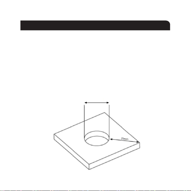
• Cut a 90mm hole in the surface allowing a 25mm clearance around the hole (see Fig. 1)
Fig. 1
90-92mm
Page 4
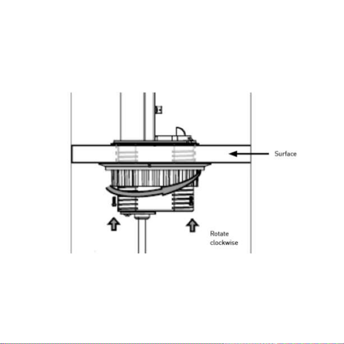
• Remove the mounting collar and rubber gasket by rotating anti-clockwise
• Insert the product through the hole, place into the desired orientation, insert the rubber
gasket, and tighten the mounting collar to the underside (see Fig. 2)
Fig. 2
• Connect to mains supply via the pre-wired cable and plug
Page 5
OPERATION
locked in position (see Fig 3a)
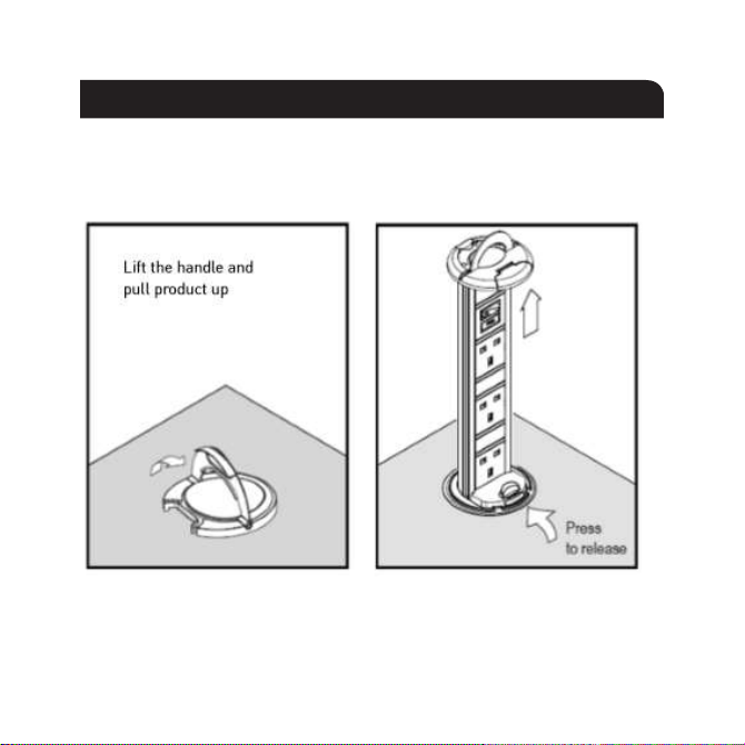
• To raise the product, gently lift the handle on the top cover. Raise until it clicks, this
means it’s locked in position (see Fig. 3a)
• To lower the product, press the release button (see Fig. 3b)
Fig. 3a Fig. 3b
• Always use the handle to raise/lower the product (see Fig. 4)
Page 6

GENERAL
This product should be recycled in the correct manner when it reaches the end of its life.
Check local authorities for where facilities exist.
Clean with a soft dry cloth, do not use any cleaning products or solvents which may
damage the product.
WARRANTY
This product has a warranty of 1 year from date of purchase. Failure to install this product
in accordance with the current edition of the IEE Wiring Regulations (BS7671), improper
use, or removal of the batch code will invalidate the warranty. If this product should fail
within its warranty period it should be returned to the place of purchase for a free of
charge replacement. ML Accessories does not accept responsibility for any installation
costs associated with the replacement product. Your statutory rights are not affected. ML
Accessories reserve the right to alter product specification without prior notice..
Page 7

locked in position (see Fig 3a)
• To lower the product, press the release button (see Fig 3b)
Fig. 3a Fig. 3b
Fig. 4
WARNING
This product must be disconnected from the circuit if subjected to any high voltage or
insulation resistance testing. Irreparable damage will occur if this instruction is not followed.
Please note that we do not recommend our 13A sockets be used for Electric Vehicle (EV)
charging for prolonged periods.
Page 8

(UK) MANUFACTURER ML ACCESSORIES LTD,
UNIT E CHILTERN PARK, BOSCOMBE ROAD,
(EU) SLV LIGHTING GROUP, DAIMLERSTRASSE 21-23,
52531 ÜBACH-PALENBERG, GERMANY
EMAIL: [email protected]
SUPPLIED BY:
DUNSTABLE LU5 4LT,
WWW.MLACCESSORIES.CO.UK
MADE IN CHINA
11
ML Accessories Limited LU5 4LT
www.mlaccessories.co.uk
Made in China
AKJUN22_V4
 Loading...