

Page 1

INSTALLATION & MAINTENANCE MANUAL
OSPCKIT
Page 2

GENERAL INSTRUCTIONS
These instructions should be read carefully and retained after installation by the end user for
future reference and maintenance.
These instructions should be used to aid the installation of the following product:
OSPCKIT
SAFETY
• This product must be installed in accordance with the latest edition of the IEE Wiring Regulations (BS7671)
and current Building Regulations. If in any doubt, consult a qualified electrician
• Please isolate mains prior to installation or maintenance
• Check the total load on the circuit (including when this product is fitted) does not exceed the rating of the
circuit cable, fuse, or circuit breaker
• Please note the IP (Ingress Protection) rating of this product when deciding the location for installation
• Do not overload this accessory or subject it to conditions outside its rating
• This product is Class II double insulated
• This product is IP66 rated
INSTALLATION
• Provide power to the required point of installation (refer to BS7671 for correct cabling methods). Suitable IP
rated junction boxes should be used where required
• The power source connections should be local and accessible via a suitable IP rated enclosure
• Round cable should be used for the mains supply. The use of flat cable will cause water ingress to the sensor
• Using the mounting bracket as a template, mark the location for, and drill the fixing holes ensuring not to
infringe with any gas/water pipes or electrical cables
• Fix the bracket to a suitable solid surface using the screws provided
• Unscrew the three screws on the bottom of the sensor and remove the plastic cover
Page 3
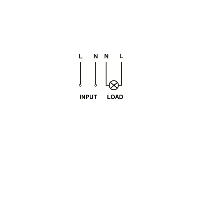
• Feed the cables through the compression glands on the bottom of the sensor
• Connect the sensor to the mains supply ensuring the correct polarity is observed (see Fig. 1): L - Live
(brown), N - Neutral (blue)
• Connect the load to the sensor ensuring the correct polarity is observed (see Fig. 1): L - Live (brown),
N - Neutral (blue)
Fig. 1
• Adjust the lux level
• Reattach the plastic cover and tighten the compression glands
• Slide the sensor onto the mounting bracket
• Switch on and check for correct operation
Page 4

SENSOR SETTING
• By turning the knob with the aid of a small flat-head screwdriver, the lux levels can be adjusted from a
minimum of 10 lux to a maximum of 50 lux (see Fig. 2)
Fig. 2
WARNING
This product must be disconnected from the circuit if subjected to any high voltage or insulation resistance
testing. Irreparable damage will occur if this instruction is not followed.
GENERAL
Clean the external surfaces with a damp cloth using a mild solution of detergent and warm water only, do
not use aggressive cleaning products or solvents which may damage the product.
This product should be recycled in the correct manner when it reaches the end of its life. Check local
authorities for where facilities exist.
Page 5

WARRANTY
This product has a warranty of 1 year from the date of purchase. Failure to install this product in accordance
with the current edition of the IEE Wiring Regulations (BS7671), improper use, or removal of the batch
code will invalidate the warranty. If this product should fail within its warranty period, it should be returned
to the place of purchase for a free of charge replacement. ML Accessories does not accept responsibility for
any installation costs associated with the replacement product. Your statutory rights are not affected. ML
Accessories reserve the right to alter product specification without prior notice.
Page 6
INTERNATIONAL
INTERNATIONAL
CONTACT DETAILS
INTERNATIONAL
CONTACT DETAILS
CONTACT DETAILS
ML Accessories Limited LU5 4LT
www.mlaccessories.co.uk
116
AVJUL21_V1
 Loading...