

Page 1

INSTALLATION & MAINTENANCE MANUAL
OP9RCD
Page 2

GENERAL INSTRUCTIONS
These instructions should be read carefully and retained after installation by the
end user for future reference and maintenance.
These instructions should be used to aid installation of the following product:
OP9RCD
SAFETY
• This product must be installed in accordance with the latest edition of the IEE Wiring
Regulations (BS7671) and current Building Regulations. If in any doubt, consult a
qualified electrician
• Please isolate mains prior to installation or maintenance
• Check the total load on the circuit (including when this product is fitted) does not exceed
the rating of the circuit cable, fuse, or circuit breaker
• Please note the IP (Ingress Protection) rating of this product when deciding the location
for installation
• This product is Class I and must be earthed
• This product is IP66 rated
Page 3
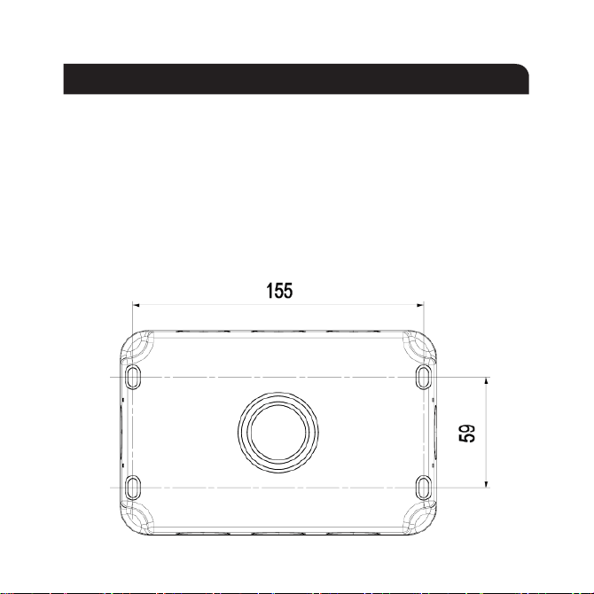
INSTALLATION
Note: the unit should be fixed to a rigid flat surface as unevenness could cause damage to
the product or affect operation
• Provide power to the required point of installation (refer to BS7671 for correct cabling
methods)
• Remove the front assembly from the backbox and carefully lift off the gasket. Drill the
required number of fixing holes in the backbox (see Fig. 1)
• Using the backbox as a template, mark the location for, and drill the fixing holes ensuring
not to infringe with any gas/water pipes or electrical cables
Fig. 1
Page 4
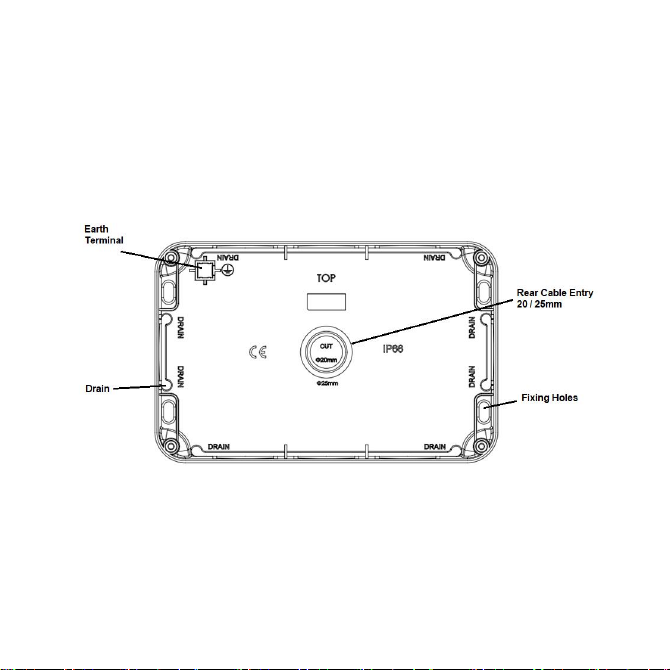
• The backbox has drain hole drilling guides marked (see Fig. 2). Drilling a drain hole is
advised if the unit is installed in a location subject to temperature fluctuations where
build-up of condensation may occur. It is not advised if the unit will be subject to high
pressure jets, as drilling a drain hole will reduce the IP rating. A 3-5mm hole should be
drilled at the bottom back edge of the enclosure where marked. If wiring in conduit to the
bottom entry then the drain hole should be drilled at the lowest point of the conduit run not in the backbox
Fig. 2
• Remove one or more of the pre-fitted blank plugs as required by pushing out from the
inside and install a suitable IP rated gland or adaptor (not supplied). For rear entry, cut or
drill a 20/25mm hole where marked and install a suitable IP rated grommet (not supplied).
Unused cable entries must have the blank plugs fitted
• Feed the mains cable into the unit and secure the base plate to the surface. The fixing holes
are slotted to allow some rotational adjustment
Page 5
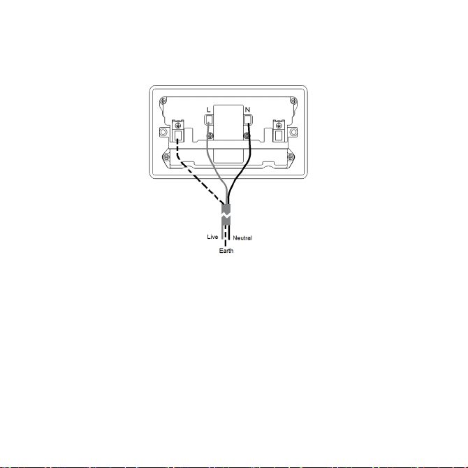
• Replace the gasket onto the backbox, then wire as shown in Fig. 3 ensuring that correct
polarity is observed: L - Live (brown), E - Earth (green/yellow), N - Neutral (blue)
Fig. 3
• An earth connection must be made to the earth terminal of the socket. Use green/yellow
sleeving on earth conductors that are not insulated. The earth terminal in the backbox is
provided for convenience and does not need to be connected
• Check all electrical connections are secure with no loose strands of cable
• Ensuring the gasket does not become damaged or pinched, fit the socket assembly onto
the backbox, taking care not to compress, damage or trap any cables, and secure with the
screws provided - do not overtighten
• Fit screw covers
• Switch on and check for correct operation
• For security, and to prevent unwanted tampering with the product, a lug feature with a
6mm hole is provided to accept a padlock or similar locking security device (not included)
Page 6

RCD TEST PROCEDURE
Press the green RESET button to switch on the supply. The red indicator should appear.
To test that the RCD is operating correctly, press the yellow TEST button. The red indicator should
turn green, this will disconnect the load. To restore power, press the green RESET button. The red
indicator should reappear.
If the RCD should trip due to a fault, the RESET button can be pressed after the fault is rectified.
If the RCD will not reset, remove any connected loads and check for faults, water ingress or
damage.
Following a power cut the RCD will automatically reset itself and does not need manually
resetting. Care should be taken to avoid connected loads powering up without warning.
The TEST button should be pressed at regular intervals to check the RCD is functioning correctly.
We recommend testing every 6 months. If the red indicator does not turn green when the TEST
button is pressed, do not use.
Page 7

WARNING
To ensure continued safe and proper weatherproof operation, the unit must not be left with
the cover raised open or the catch left unlocked.
This product must be disconnected from the circuit if subjected to any high voltage or
insulation resistance testing. Irreparable damage will occur if this instruction is not followed
GENERAL
This product should be recycled in the correct manner when it reaches the end of its life.
Check local authorities for where facilities exist.
To clean the external surfaces, securely close the cover and use a damp cloth with a mild
solution of detergent and warm water only, do not use aggressive cleaning products or
solvents which may damage the product. If it is necessary to clean inside the cover, use a
soft dry cloth only.
Do not use any source of high-pressure washers to maintain or clean this product.
WARRANTY
This product has a warranty of 1 year from date of purchase. Failure to install this product
in accordance with the current edition of the IEE Wiring Regulations (BS7671), improper
use, or removal of the batch code will invalidate the warranty. If this product should fail
within its warranty period, it should be returned to the place of purchase for a free of
charge replacement. ML Accessories does not accept responsibility for any installation
costs associated with the replacement product. Your statutory rights are not affected. ML
Accessories reserve the right to alter product specification without prior notice.
Page 8
ML ACCESSORIES LIMITED
UNIT E, CHILTERN PARK, BOSCOMBE ROAD,
DUNSTABLE, LU5 4LT
(EU) AUTHORISED REPRESENTATIVE
NNUKS HOLDING GMBH,
NIEDERKASSELER LOHWEG 18,
40547 DÜSSELDORF, GERMANY
EMAIL: [email protected]
WWW.MLACCESSORIES.CO.UK
MADE IN CHINA
11
AVJUN21_V1
 Loading...