

Page 1

INSTALLATION & MAINTENANCE MANUAL
INSTALLATION & MAINTENANCE MANUALINSTALLATION & MAINTENANCE MANUALINSTALLATION & MAINTENANCE MANUAL
LWBMIC
Page 2

GENERAL INSTRUCTIONS
These instructions should be read carefully and retained after installation by the end
user for future reference and maintenance.
These instructions should be used to aid installation of the following product:
LWBMIC
SAFETY
• This product must be installed in accordance with the latest edition of the IEE Wiring Regulations
(BS7671) and current Building Regulations. If in any doubt, consult a qualified electrician
• Please isolate mains prior to installation or maintenance
• Check the total load on the circuit (including when this product is fitted) does not exceed the
rating of the circuit cable, fuse or circuit breaker
• Please note the IP (Ingress Protection) rating of this product when deciding the location for
installation
• Do not overload this accessory or subject it to conditions outside its rating
• This product is Class II double insulated
• This product is IP65 rated
INSTALLATION
Note - microwave sensors may not be suitable for all installations, for example enclosed
spaces, as they are able to detect movement through non-metallic surfaces like plasterboard
and thin doors.
This product is designed for use with the LWB range of luminaires
Page 3
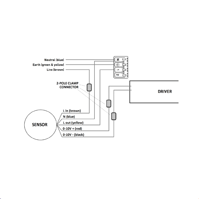
• Remove a 20mm knockout from one end of the luminaire. If using the emergency kit
LWBEMKIT, it is recommended that the sensor be installed on the opposite end of the fitting in
order not to obscure the emergency LED indicator
• Feed the mains cable through the knockout and secure using the lockring provided
• Ensuring correct polarity is observed, carefully wire as shown in Fig. 1, using the three 2-pole
clamp connectors provided
DIM+ (Purple)
DIM- (Pink)
Fig. 1
• This product is compatible with the emergency kit LWBEMKIT, but is not compatible
with an external 0-10V dimmer
• See below for microwave sensor settings
• Switch on and check for correct operation
Page 4
SENSOR SET-UP
SENSOR SET-UP
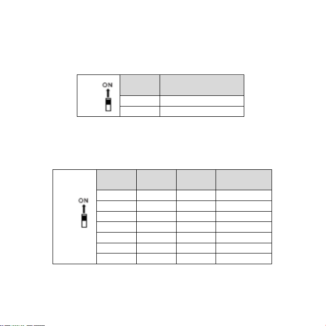
Detection area
Detection area can be reduced by selecting the DIP switch layout below
DETECTION
RANGE
On
100%
-
50%
SENSOR SET-UP
Detection area
Detection area can be reduced by selecting the DIP switch layout below
1
DETECTION
RANGE
On
100%
-
50%
Hold time
This is the time that the luminaire will remain at 100% brightness after no motion is detected
HOLD
TIME
On
On
On
5 sec
-
On
On
30 sec
On
On - 1 min
- - On
5 min
-
On - 10 min
On - -
20 min
- - -
30 min
Detection Range
Detection range can be reduced by selecting the DIP switch layout below
1
Hold Time
This is the time that the luminaire will remain at 100% brightness after no
motion is detected
2 3 4
Page 5

1
DETECTION
RANGE
On
100%
-
50%
Hold time
This is the time that the luminaire will remain at 100% brightness after no motion is detected
2 3 4
HOLD
TIME
On
On
On
5 sec
-
On
On
30 sec
On
On - 1 min
- - On
5 min
-
On - 10 min
On - -
20 min
- - -
30 min
Daylight sensor
This is the ambient light level at which the luminaire is required to operate. If set to “DISABLE”, the luminaire will
operate when motion is detected regardless of the ambient light level
DAYLIGHT
SENSOR
On
On
On
Disable
-
On
On
120 lux
On
On - 80 lux
- - On
50 lux
-
On - 30 lux
On - -
10 lux
- - -
2 lux
1
DETECTION
RANGE
On
100%
-
50%
2 3 4
HOLD
TIME
On
On
On
5 sec
-
On
On
30 sec
On
On - 1 min
- - On
5 min
-
On - 10 min
On - -
20 min
- - -
30 min
Daylight sensor
This is the ambient light level at which the luminaire is required to operate. If set to “DISABLE”, the luminaire will
operate when motion is detected regardless of the ambient light level
5 6 7
DAYLIGHT
SENSOR
On
On
On
Disable
-
On
On
120 lux
On
On - 80 lux
- - On
50 lux
-
On - 30 lux
On - -
10 lux
- - -
2 lux
Standby period
This is the time that the luminaire will remain at the “standby dimming level” in the absence of movement. If set
to “DISABLE”, the low light level will be maintained until motion is detected
STANDBY
PERIOD
On
On
On
0 sec
-
On
On
10 sec
On
On - 30 sec
- - On
1 min
-
On - 5 min
On - -
30 min
- - -
+∞
Daylight Sensor
This is the ambient light level at which the luminaire is required to operate. If set
to “DISABLE”, the luminaire will operate when motion is detected regardless of
the ambient light level
5 6 7
Standby Period
This is the time that the luminaire will remain at the “standby dimming level” in the
absence of movement. If set to “DISABLE”, the low light level will be maintained until motion is
detected
8 9 10
Page 6
Standby Dimming Level
1
DETECTION
RANGE
On
100%
-
50%
2 3 4
HOLD
TIME
On
On
On
5 sec
-
On
On
30 sec
On
On - 1 min
- - On
5 min
-
On - 10 min
On - -
20 min
- - -
30 min
5 6 7
DAYLIGHT
SENSOR
On
On
On
Disable
-
On
On
120 lux
On
On - 80 lux
- - On
50 lux
-
On - 30 lux
On - -
10 lux
- - -
2 lux
Standby period
This is the time that the luminaire will remain at the “standby dimming level” in the absence of movement. If set
to “DISABLE”, the low light level will be maintained until motion is detected
8 9 10
STANDBY
PERIOD
On
On
On
0 sec
-
On
On
10 sec
On
On - 30 sec
- - On
1 min
-
On - 5 min
On - -
30 min
- - -
+∞
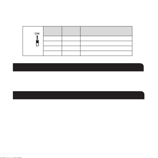
Standby dimming level
This refers to the light level required during the “standby period”
STANDBY
DIMMING LEVEL
On
On
10%
On
-
20%
-
On
30%
-
-
50%
This refers to the light level required during the “standby period”
11 12
WARNING
This product must be disconnected from the circuit if subjected to any high voltage or
insulation resistance testing. Irreparable damage will occur if this instruction is not followed.
GENERAL
This product should be recycled in the correct manner when it reaches the end of its life.
Check local authorities for where facilities exist.
Clean with a soft dry cloth only, do not use aggressive cleaning products or solvents which
may damage the product.
Page 7

WARRANTY
This product has a warranty of 5 years from date of purchase. Failure to install this product
in accordance with the current edition of the IEE Wiring Regulations (BS7671), improper
use, or removal of the batch code will invalidate the warranty. If this product should fail
within its warranty period, it should be returned to the place of purchase for a free of
charge replacement. ML Accessories does not accept responsibility for any installation costs
associated with the replacement product. Your statutory rights are not affected.
ML Accessories reserve the right to alter product specification without prior notice.
Page 8

Supplied By:
ML Accessories Ltd, Unit E Chiltern Park, Boscombe Road, Dunstable LU5 4LT,
nnuks Holding GmbH, Niederkasseler Lohweg 18,
(UK) Manufacturer
www.mlaccessories.co.uk
(EU) Authorised Representative
40547 Düsseldorf, Germany,
Email: [email protected]
122
DCJUL22_V3
Page 9

Manufacturers Declaration of Conformity
For ML Accessories (Knightsbridge)
Electrical products in accordance with UKCA marking
ML Accessories Ltd. declare that all products have been designed, manufactured, and tested in
accordance with the requirements of the relevant legislation
UKCA marking legislation
UK SI 2016 No. 1091 Electro Magnetic Compatibility Regulations 2016
UK SI 2016 No. 1101 The Electrical Equipment (Safety) Regulations 2016
UK SI 2012 No. 3032 Restriction of the use of Certain Hazardous Substances in Electrical and
Electronic Equipment Regulations 2012
UK SI 2017 No. 1206 Radio Equipment regulations 2017
UK SI 2021 No. 1095 The Ecodesign for Energy-Related Products and Energy
Information (Lighting Products) Regulations 2021
Included Legislation
UK SI 2008 No. 2852 UK REACH
UK SI 2013 No. 3113 WEEE
Safety Standards
Full individual declarations and specific safety standards applicable to relevant product series can be found on
our website www.mlaccessories.co.uk
We hereby declare that the equipment named above has been designed to comply with the relevant
sections of the above referenced specifications. The products comply with all essential requirements of
the directives.
Scott Brewer Catherine Connolly
Head of Technical CEO
ML Accessories Ltd. Unit E Chiltern Park, Boscombe Road, Dunstable. Bedfordshire, LU5 4LT
This declaration becomes invalid if technical or operational modifications are introduced without ML Accessories Ltd. written consent.
Page 10
Manufacturers Declaration of Conformity
For ML Accessories (Knightsbridge)
Electrical products in accordance with CE marking
ML Accessories Ltd. Declare that all products have been designed, manufactured, and tested in
accordance with the requirements of the relevant legislation
CE marking legislation
In Accordance with the following Directives:
2014/35/EU Low Voltage Directive
2014/30/EU EMC Directive
2014/53/EU Radio Equipment Directive
Including Legislation
1907/2006 REACH
2015/863 RoHS
2021/341 ERP
Safety Standards
Full individual declarations and specific safety standards applicable to relevant product series can be found on
our website www.mlaccessories.co.uk
We hereby declare that the equipment named above has been designed to comply with the relevant
sections of the above referenced specifications. The product complies with all essential requirements of
the directives.
Scott Brewer Catherine Connolly
Technical Manager CEO
ML Accessories Ltd. Unit E Chiltern Park, Boscombe Road, Dunstable. Bedfordshire, LU5 4LT
This declaration becomes invalid if technical or operational modifications are introduced without ML Accessories Ltd. written consent.
 Loading...