

Knightsbridge IP663G, IP665G Installation & Maintenance Manual
IP66 REMOTE CONTROLLED SWITCH BOX
ML Accessories Limited
LU5 5TA
www.mlaccessories.co.uk
PS-03-14-V1
89
IP
66
230V
50Hz
INSTALLATION & MAINTENANCE MANUAL
IP663G & IP665G
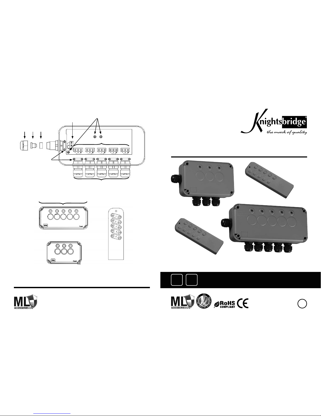
Supply terminals
PCB screws
Load terminals
Load glands
Handset
Indicator lamps
5 way power controller
3 way power controller
Supply gland
Cable clamps
1 2 3
Figure 1
Figure 2

These instructions should be read carefully and retained after installation for further reference
and maintenance.
• Before installation/maintenance, ensure that the mains supply is switched off and the circuit
fuses are removed or circuit breakers switched off
• This product must be installed in accordance with the latest edition of the IEE Wiring
Regulations and current Building Regulations. If in any doubt, please consult a
qualified electrician
• This product is IP66 rated and suitable for external applications. (Weatherproof rating may be
compromised if drain hole is opened)
• This product is class I rated and must be earthed
• This accessory is designed to be used with round cable with an outside diameter of between
6mm and 12mm
• 230V 50Hz voltage 13A
• Do not overload this accessory or subject it to conditions outside its weatherproof rating
• Please recycle this unit
GENERAL INSTRUCTIONS:
SAFETY:
INSTALLATION:
SETTING UP THE REMOTE CONTROL:
1. Remove the 4 x fixing screws around the lid/cover, and PCB securing screw(s) (IP665G x 2)
2. Using the back box as a template, mark the fixing holes and fix the back box to a fixed level
location (e.g. wall), ensuring suitable wall fixings are used. Refit the screw mounting hole caps
(failure to fit these caps will compromise the IP rating). The load glands must be facing down
CONNECTING THE MAINS SUPPLY
1. Remove items 1, 2 & 3 (see figure 1 on back page) from the supply gland, ensuring that the
body stays fully tightened in the power controller. Failure to do this may compromise the
weatherproof rating
2. Slide items 1 & 3 over the supply cable (item 1 first) and push the cable through the supply
gland body. Item 2 may be discarded
3. Remove the cable clamp by undoing the 2 screws and lifting off
4. Connect the supply cable to the relevant supply terminals ensuring correct
polarity is observed:-
ACL – LIVE (BROWN) ACN – NEUTRAL (BLUE) FGND - EARTH (GREEN/YELLOW)
All Earth connections must be made and maintained. Use green/yellow sleeving on earth
conductors that are not insulated
5. Replace the cable clamp around the outer sheath of the cable and fully tighten
the 2 screws
6. Slide item 3 along the cable and into the supply gland body then fully tighten item 1 (failure to
do this may compromise the weatherproof rating)
CONNECTING THE LOAD SUPPLY
1. Remove items 1, 2 & 3 (see figure 1 on back page) from the load gland ensuring the
body stays fully tightened in the power controller (failure to do this may compromise the
weatherproof rating)
2. Slide items 1 & 3 over the load cable (item 1 first) and push the cable through the load gland
body. Item 2 may be discarded
3. Remove the cable clamp by undoing the 2 screws and lifting off
4. Connect the supply cable to the relevant supply terminals ensuring correct polarity
is observed:-
FGND - EARTH (GREEN/YELLOW) ACN - NEUTRAL (BLUE) ACL - LIVE (BROWN)
All earth connections must be made and maintained. Use green/yellow sleeving on earth
conductors that are not insulated
5. Repeat steps 1 through 5 for each load to be connected
6. Ensure the gasket is fitted to the inside of the lid and fix the lid to the back box using the
screws provided. The screws must be fully tightened to prevent ingress of moisture
7. When installation is correctly completed, reconnect mains supply
IMPORTANT WARNING
Each switch is individually fused; the rating of the fuse is marked on the circuit board adjacent
to the fuse, do not overload any circuit. Should an individual circuit stop working, check the fuse
on the circuit board and replace with one of the same rating if required. Fuse ratings, from left
(nearest to the supply gland) are as follows:
5 ways: 5A, 2.5A, 2.5A, 2A, 1A
3 ways: 8A, 2.5A, 2.5A
1. Remove the battery cover from the handset and insert a 1.5V AAA battery (not supplied)
2. Press the “ON” CHN-1 button of the remote control and the first left hand indicator lamp on
the power controller should illuminate. Mains 230V power is now supplied to the terminals of
channel 1 and equipment connected to these terminals will operate
3. Press the “OFF” CHN-1 button of the remote control and the first left hand indicator lamp on
the power controller should turn off. Mains 230V power is now off to the terminals of channel
1 and equipment connected to these terminals will not operate
4. Repeat steps 1 - 3 for all channels to check for correct operation
NOTE
All buttons/channels on the handset and power controller are pre-set at the factory and cannot
be changed.
 Loading...