

Page 1

INSTALLATION & MAINTENANCE MANUAL
CAPWGU
Page 2

GENERAL INSTRUCTIONS
These instructions should be read carefully and retained after installation by the end user for
future reference and maintenance.
These instructions should be used to aid installation of the following product:
CAPWGU
SAFETY
• This product must be installed in accordance with the latest edition of the IEE Wiring Regulations (BS7671)
and current Building Regulations. If in any doubt, consult a qualified electrician
• Please isolate mains prior to installation or maintenance
• Check the total load on the circuit (including when this product is fitted) does not exceed the rating of the
circuit cable, fuse, or circuit breaker
• This product is safe for use as a drive-over fitting 1000kg @ 5mph (with half-lip cover removed)
• Please note the IP (Ingress Protection) rating of this product when deciding the location for installation
• This product should be installed in the upright position
• This product is Class I and must be earthed
• This product is IP65 rated
INSTALLATION
• Provide power to the required point of installation (refer to BS7671 for correct cabling methods). Suitable IP
rated junction boxes should be used where required
• The power source connections should be local and accessible via a suitable IP rated enclosure
• Cut a suitable hole in the mounting surface as per the cut-out details (see Fig.1) ensuring not to infringe with
any joists, gas/water pipes or electrical cables
Page 3
the circuit cable, fuse, or circuit breaker
Suitable IP rated junction boxes should be used where required
infringe with any joists, gas/water pipes or electrical cables
Cut-out with sleeve
Cut-out without sleeve
70mm
65mm
Fig. 1
necessary for installation into decking
sit on top of the fitting (see Fig. 2)
Cut-out with sleeve Cut-out without sleeve
Fig. 1
70mm 65mm
• Please note this product is supplied with a sleeve for direct mounting in the ground. The sleeve is not
necessary for installation into decking
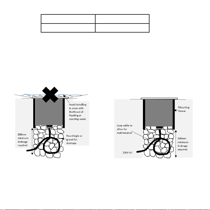
• We recommend not installing in areas where there is a high risk of flooding or areas where water may sit on
top of the fitting (see Fig. 2)
• Ensure a minimum of 300mm of drainage is put below the luminaire (see Fig. 2)
Fig. 2
• There must be enough cable below the luminaire to carry out maintenance work (see Fig. 3)
Page 4
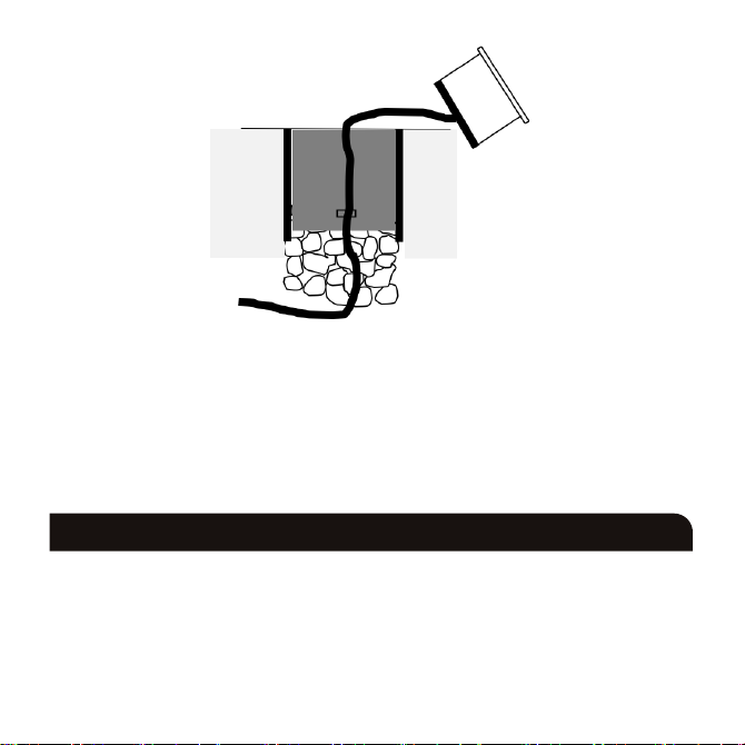
Fig. 3
• Connect the luminaire to the mains supply ensuring the correct polarity is observed L - Live (brown),
E - Earth (green/yellow), N - Neutral (blue).
• Remove the bezel, lens, and seal by unscrewing the two screws on top of the luminaire and insert a suitable
GU10 lamp
• Replace the bezel, lens and seal
• Switch on and check for correct operation
WARNING
Care should be taken when installing into high ‘clay’ content soils which naturally retain water and have poor
drainage. We recommend IP67 or IP68 products to be installed where these environmental conditions occur as
IP65 luminaires will likely be compromised.
This product is not suitable for installation in or near a coastal or marine environment.
Page 5

GENERAL
Clean the external surfaces with a damp cloth using a mild solution of detergent and warm water only, do not
use aggressive cleaning products or solvents which may damage the product.
Do not use any source of high-pressure washers to maintain or clean this luminaire.
A light film of acid-free oil is recommended after installation and maintained periodically (2-3 times a year) to
aid corrosion prevention.
This product is dimmable dependent on lamp type
This product should be recycled in the correct manner when it reaches the end of its life. Check local authorities
for where facilities exist.
WARRANTY
This product has a warranty of 1 year from date of purchase. Failure to install this product in accordance with
the current edition of the IEE Wiring Regulations (BS7671), improper use, or removal of the batch code will
invalidate the warranty. If this product should fail within its warranty period, it should be returned to the place
of purchase for a free of charge replacement. ML Accessories does not accept responsibility for any installation
costs associated with the replacement product. Your statutory rights are not affected. ML Accessories reserve
the right to alter product specification without prior notice.
Page 6
INTERNATIONAL
INTERNATIONAL
CONTACT DETAILS
INTERNATIONAL
CONTACT DETAILS
CONTACT DETAILS
ML Accessories Limited LU5 4LT
www.mlaccessories.co.uk
02
AKJUL21_V2
 Loading...