

Page 1

Page1of34
Page 2

Page2of34
Page 3

Page3of34
TABLE OF CONTENTS:
4 INTRODUCTION
5 CERTIFICATION CE
5 CONFORMITY ACCORDING TO CE DIRECTIVE
6 DANGER WARNINGS
7 GENERAL WARNINGS
7 LIMITATIONS
8 RISK AWARENESS
10 TECHNICAL SPECIFICATIONS
12 USAGE
29 PRE DIVE PREPARATIONS
33 MAINTENANCE ROUTINE
33 WARRANTY
Page 4

Page4of34
INTRODUCTION
Thank you for purchasing a KNIGHT DIVERS BCD.
Our BCDs are made exclusively with the best European production materials, selected and
tested in order to offer a product of the highest quality.
Development and continuous research allow us to be constantly evolving.
Our BCDs have been designed to meet the requirements of the UNI EN 1809: 2014 + A1:
2016 standard with regard to the requirements for buoyancy compensators.
Design and production are carried out entirely in MALTA. All the materials used are
certified non-toxic and hypoallergenic to contact with the skin, all in compliance with the
protection of the health of the user, workers and the environment. Each BCD is
individually tested to prove the pressure seal, the functionality of the valves and the
connection hose.
It is important to read the recommendations in the following pages very carefully.
KNIGHT DIVERS Ltd is at your disposal for any eventual clarification regarding the use of
the BCD. For any query, please contact us at:
KNIGHT DIVERS Ltd
62,Triq L-Gholjiet
Mellieha MLH 2105
Malta
Phone +356 7903 0676
www.knightdivers.eu
info@knightdivers.eu
Page 5

Page5of34
CE CERTIFICATION
The BCDs described in this manual have undergone a CE type examination, verified and
certified by the RINA laboratory, S.p.A. - Via Corsica, 12 - 16128 Genoa - Italy, Notified
Body No. 0474 in compliance with the EN 1809: 2014 + A1: 2016 standard as a stabilizing
jacket (Class II).
CONFORMITY ACCORDING TO CE DIRECTIVE
The undersigned manufacturer KNIGHT DIVERS Ltd with headquarters in 62, Triq LGholjiet, Mellieha MLH 2105 MALTA declares that the PPE described below: Floating
compensators (balancing jackets) for underwater use models:
GR 13 One size (adjustable from XS to XXL)
GR 13 TEK One size (adjustable from XS to XXL)
GR 15 One size (adjustable from XS to XXL)
GR 15 TEK One size (adjustable from XS to XXL)
GR 19 One size (adjustable from XS to XXL)
GR 19 TEK One size (adjustable from XS to XXL)
GR 19 R One size (adjustable from XS to XXL)
comply with the provisions of Directive 89/686/CEE (implemented in Italy with Legislative
Decree 4/12/92 No. 475 and subsequent amendments and / or additions) and with
national regulations that implement the harmonized standard EN1809: 2014 + A1: 2016 ;
are identical to the PPE subjected to Certification Certificate No. PPE416917CS/001 and
No. PPE416917CS/002 issued by RINA Services S.p.A. via Corsica 12, 16128 Genoa
(Notified body no. 0474).
Page 6
Page6of34
DANGER WARNINGS
This manual contains graphic symbols to inform you about the risks and dangers you may
encounter in the use and maintenance of the BCDs.
These graphic symbols and their associated captions are:
DANGER :
Indicates an imminent hazard which, if not avoided, may result in serious injury
or death.
ATTENTION :
Indicates a potential hazard which, if not avoided, may result in serious injury
or death.
CAUTION :
Indicates a potential hazard which, if not avoided, may result in slight or
moderate injury. May also indicate the unsafe execution of a procedure.
Page 7

Page7of34
GENERAL WARNINGS
Before using the BCD or any other product for scuba diving it is necessary to
follow a course held by qualified instructors and obtain the relevant license.
The use of diving equipment by unqualified persons is dangerous and may
result in serious injuries or death to the diver and his companions.
If you are not experienced in the use of this equipment, we recommend that you
familiarize yourself with its operation during shallow depth test diving and in favorable
conditions; if necessary, it is advisable to contact a qualified instructor for a refresher
course. During the assembly and setting of the BCD, all possible precautions have been
implemented to provide a highly reliable product over time. Such measures can be
rendered inefficient if the user does not use the BCD correctly and does not provide
adequate maintenance. KNIGHT DIVERS Ltd declines all responsibility for any problems
arising from failure to observe the recommendations in this manual.
For any problem you can contact your dealer or contact directly KNIGHT DIVERS Ltd. To
ensure maximum safety, any repair or maintenance must only be carried out by technical
centers authorized by KNIGHT DIVERS Ltd. In case it is necessary to perform routine
maintenance operations or extraordinary maintenance, KNIGHT DIVERS Ltd makes
available its Technical Service Centre to provide all the assistance and the original
spare parts.
These BCDs have been certified according to the EN 1809 standard which provides for a
long series of functional tests up to a maximum depth of 50 meters and at temperatures
between -20 ° C and + 70 ° C.
LIMITATIONS
It is not the purpose of the EN 1809 standard to establish requirements for flotation
devices or life jackets.
The BCD is not intended to ensure a high head position on the surface in case of
unconsciousness or inability of the diver. The instructions that follow must be
integrated with those relating to the other components making up your SCUBA
set (cylinder unit or assembled double tank). Before using your assembled
cylinder or bottle assembly read carefully all the instructions for use given in
the relevant manuals.
KNIGHT DIVERS Ltd declines its responsibility for any errors in the compilation of the Use
and Maintenance Manual and, constantly working for the improvement of all its products,
reserves the right to make changes at any time, without prejudice to the essential
characteristics described herein illustrated.
Page 8
Page8of34
RISK AWARENESS
WARNING :
This booklet is not a dive manual! Read the entire manual before using this
equipment! The user manual must be retained for the entire period of the
product life!
WARNING :
According to the European standards, our BCDs are to be considered certified
only if they are complete with all the components as the original KNIGHT
DIVERS configuration, including the quick release LP hose.
For safety reasons, the BCD must only be used with the original quick release
LP hose supplied by KNIGHT DIVERS. The manufacturer cannot be held
responsible for damage to persons or property deriving from the use of
different hoses.
DANGER :
This BCD is not a life jacket or a rescue device and does not guarantee the
support in surface of an unconscious diver in a position where the face remain
out of the water.
DANGER :
Do not use this BCD until you have acquired the specific license. Use of this BCD
by divers who have not obtained the required license, may result in serious
injuries or death.
This BCD should be used up to the depth of 50 meters.
WARNING :
These BCDs have been designed to be used with normal atmospheric air
conform to requirements for breathable air as established in CEN EN 12021.
The use of this product with oxygen-enriched gas or mixtures (commonly
known as NITROX) requires specific preparation and compliance with laws of
the country where the equipment is used. If this is not done according to
recommendations, it may cause serious or fatal injury due to fires or
explosions, or seriously cause damage to the equipment.
Page 9
Page9of34
WARNING :
A bad or improper use of this BCD could result in a loss of trim, including rapid
and uncontrolled ascents and descents, with the risk of drowning or
decompression sickness.
DANGER :
Diving in an environment that is chemically, biologically, or radiologically
contaminated is extremely dangerous. The BCDs KNIGHT DIVERS must not be
used in contaminated environments.
DANGER :
Diving in ice water (in water at 5°C or less) is extremely dangerous. Do not dive
in ice water unless you have been fully trained and with specially dedicated
equipment.
DANGER :
It is essential to take good note of these hazard and danger symbols to avoid
critical situations that may occur while using the BCDs. Such situations may
result in serious injury or death.
Page 10

Page10of34
TECHNICAL SPECIFICATIONS
Buoyancyforce of the BCDs:
Model GR 13: maximum buoyancy 120 Newtons 12,2 Kilograms 13 Ltrs
Model GR 13 TEK: maximum buoyancy 120 Newtons 12,2 Kilograms 13 Ltrs
Model GR 15: maximum buoyancy 150 Newtons 15,3 Kilograms 15 Ltrs
Model GR 15 TEK: maximum buoyancy 150 Newtons 15,3 Kilograms 15 Ltrs
Model GR 19: maximum buoyancy 170 Newtons 17,3 Kilograms 19 Ltrs
Model GR 19 TEK: maximum buoyancy 170 Newtons 17,3 Kilograms 19 Ltrs
Model GR 19 R: maximum buoyancy 180 Newtons 18,4 Kilograms 19 Ltrs
Bladder
It is made of Cordura polyurethane coated (Models GR13, 15, 19 and 19R) or nylon
polyurethane double-coated (Models GR TEK).
Harness
The harness are made of 50mm polyethylene reinforced polypropylene and are completed
by five “D” rings of AISI 304 stainless steel that allow to connect to the harness different
diving accessories. The buckle is also of AISI 304 stainless steel. The belt slides inside a
series of AISI 304 stainless steel loops in order to adapt the harness to any size between
the S and XXL.
Backplate:
The backplate is made of electro polished AISI 304 stainless steel or of aluminum; nuts
and bolts of AISI 304 stainless steel.
Power inflator and overpressure valves
For safety reasons, we recommend that the first time you try to use the inflate button
when you are in surface.
The power inflator of the BCD controls a large number of functions and allows to adjust
the BCD to get a neutral trim during the dive:
Load by the button of the inflator (side button); pressing this button inflates the
BCD; it can be inflated up to a pre-established pressure that depends on the
calibration of the overpressure valve; once the maximum pressure is reached, the
air is discharged from the valve.
The top button (at the end of power inflator) allows the inflation by mouth with a
special mouthpiece: push the button and in the same time blow inside the
mouthpiece.
The top button (at the end of power inflator) allows the deflation by raising the
corrugated upwards and pressing.
Page 11

Page11of34
DANGER :
Never use the inflator mouthpiece as a regulator. The BCD is not a breathing
device. Never breathe gas from inside the BCD, it may contain liquids or
contaminants that, if inhaled, could lead to serious injuries or, in extreme
situations, to death.
Overpressure valves
The BCDs are supplied with one overpressure valve located behind on the left side at the
bottom. The overpressure valves guarantee the quick dumping of air. The function of
these valves is to automatically reduce the inner pressure of the bladder in case of
excessive inflation or in case of eventual necessity during the various phases of diving.
The valves can be opened manually pulling the cable located on the valve itself.
WARNING :
To obtain complete redundancy, only the Model GR 19 R is composed of two
independent bladders coupled. Each bladder has a complete control unit and an
overpressure and rapid discharge valve: in this case the overpressure valves are located at
the bottom, right and left.
Page 12

Page12of34
USAGE
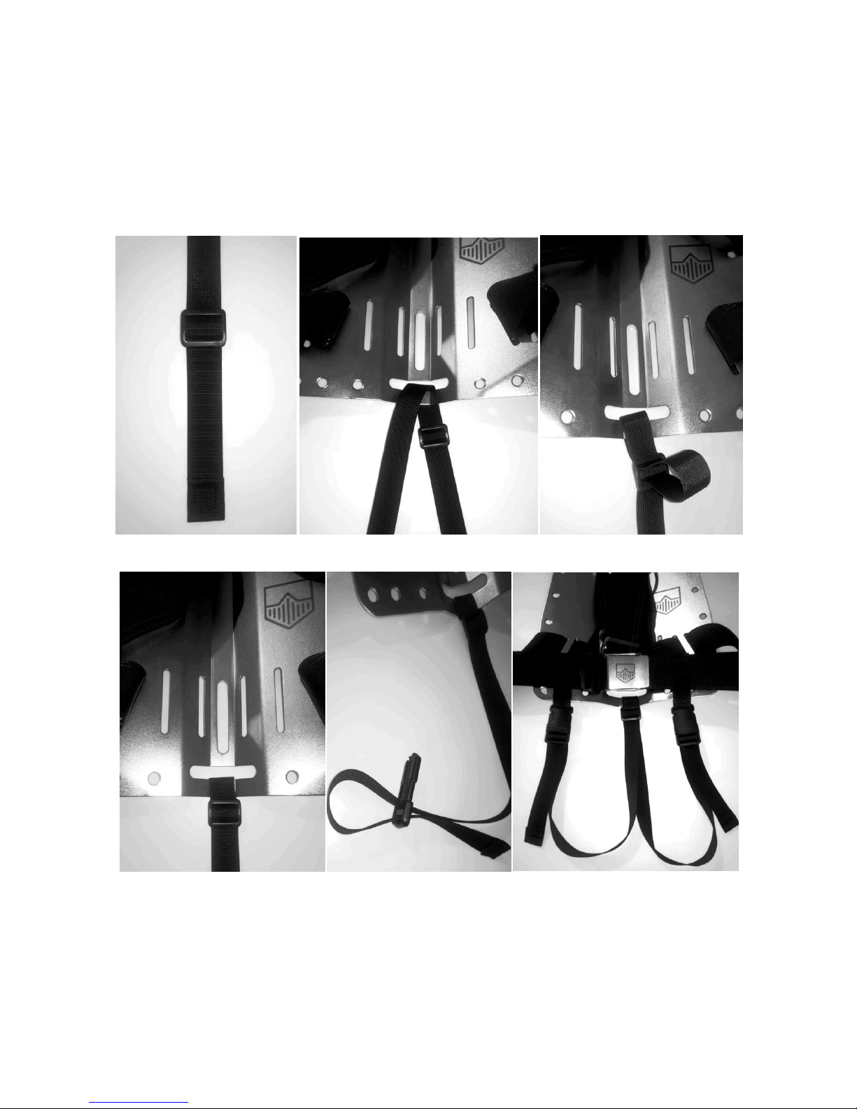
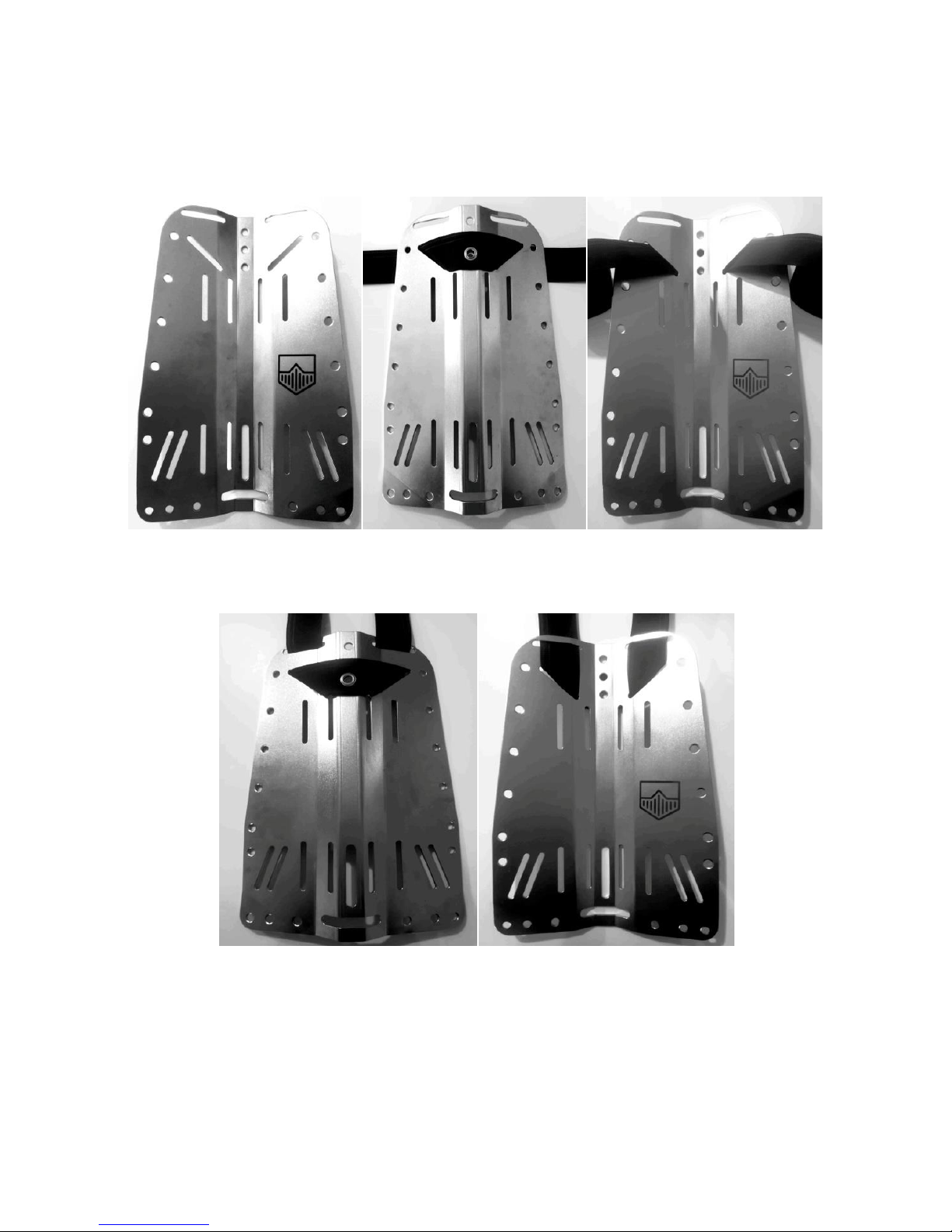
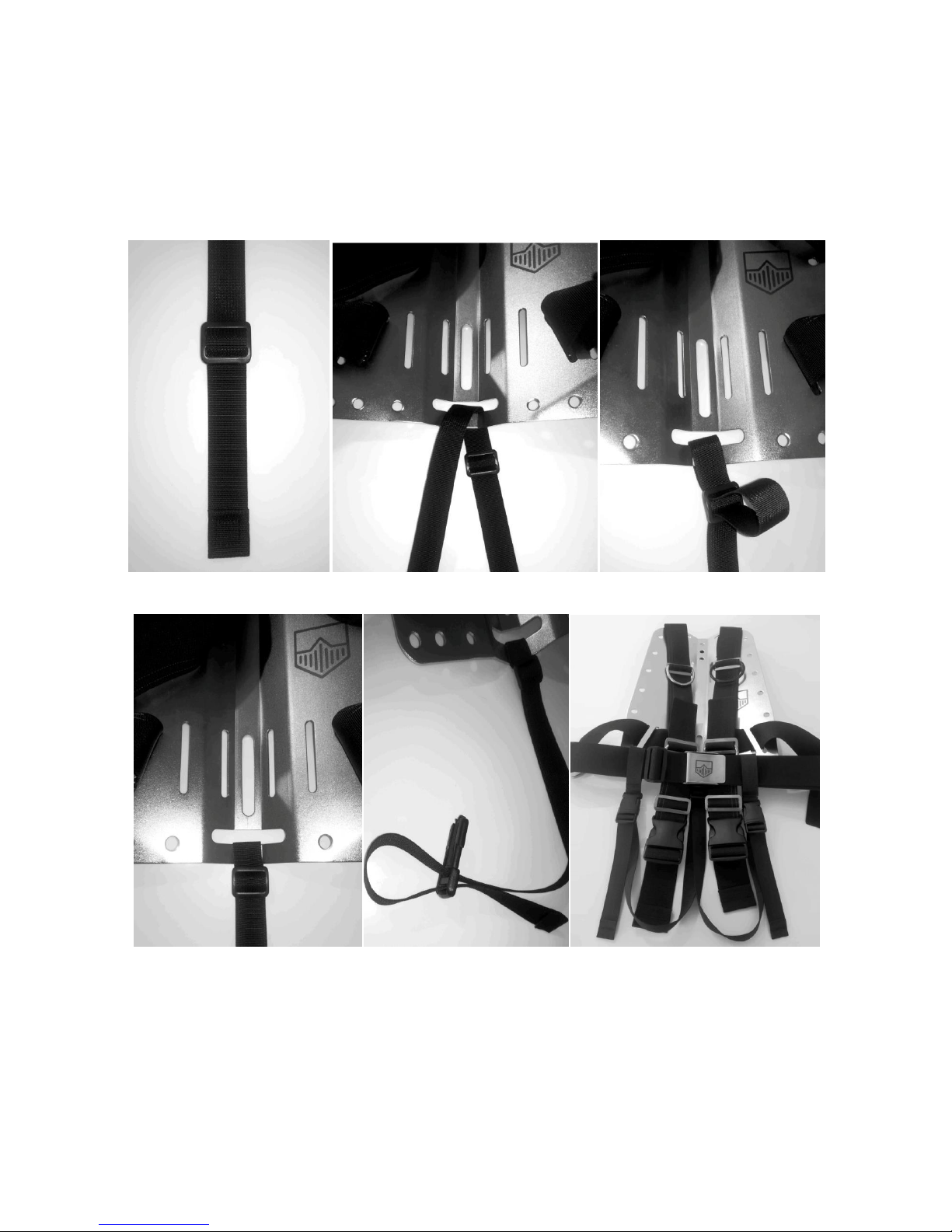
Harness assembly, “DIR” type
1) Insert the strap with the eyelet aligned in the upper back part of the backplate (Fig. 2)
and (Fig. 3).
(Fig. 1) (Fig. 2) (Fig. 3)
2) Run the strap through the upper horizontal slots of the backplate (Fig. 4) and (Fig. 5).
(Fig. 4) (Fig. 5)
Page 13

Page13of34
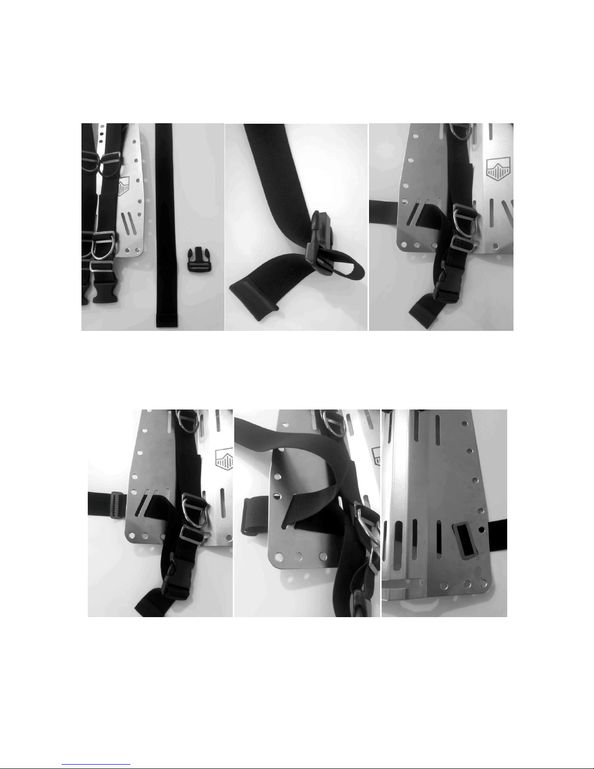
3) Insert a smooth loop and a "D" ring on the right belt (Fig. 6). Repeat the procedure on
the opposite side using the elastic accessory-holder ring (Fig. 7) and insert the retentive
band of the power inflator (Fig. 8).
(Fig. 6) (Fig. 7) (Fig. 8)
4) Insert a smooth loop and a "bent D" ring on both sides (Fig. 9) and (Fig. 10). Insert one
end of the strap from the inside outward through the inner lower sloped slot (Fig. 11).
Repeat the procedure on the opposite side (Fig.9-11).
(Fig. 9) (Fig. 10) (Fig. 11)
Page 14

Page14of34
5) Insert a toothed loop on the belt (Fig. 12) and slide it from the outside to the inside
through the sloped outer slit (Fig. 13). Repeat the procedure on the opposite side (Fig. 12-
14).
(Fig. 12) (Fig. 13)
(Fig. 14)
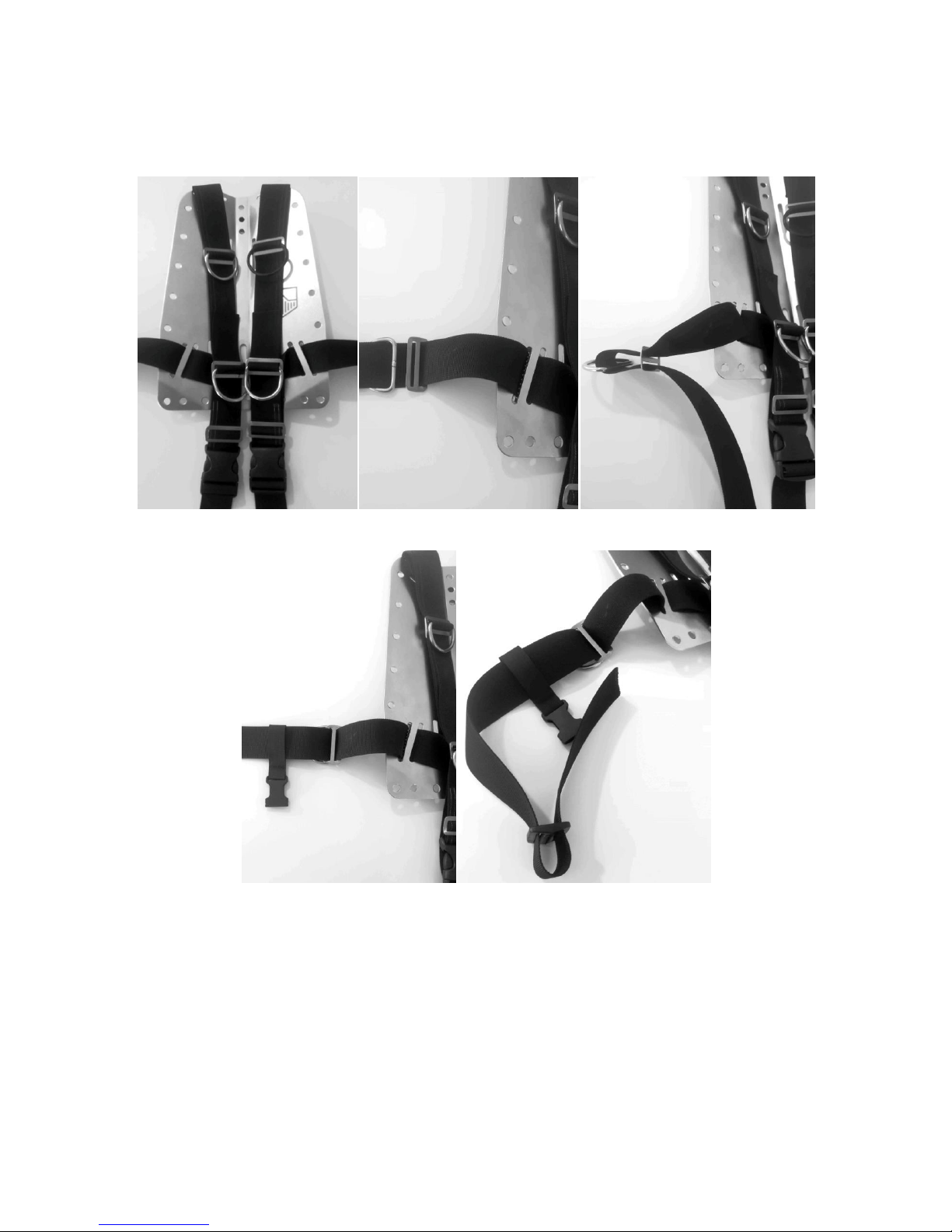
6) On the left belt end insert a smooth loop and a "D" ring about 15cm from the backplate
(Fig. 15) and (Fig. 16). Insert the female attach of the quick release buckle for the left
crotch strap (Fig. 17).
(Fig. 15) (Fig. 16) (Fig. 17)
Page 15

Page15of34
7) Still on the left belt insert the metal buckle passing and passing the belt on the buckle
following the steps illustrated by the following pictures (Fig. 18-23).
(Fig. 18) (Fig. 19) (Fig. 20)
(Fig. 21) (Fig. 22) (Fig. 23)
8) On the right belt end insert a smooth loop and a "D" ring about 15cm from the
backplate (Fig. 24). Insert the female attach of the quick release buckle for the right
crotch strap and lock it with a plastic toothed loop (Fig. 25).
(Fig. 24) (Fig. 25)
Page 16
Page16of34
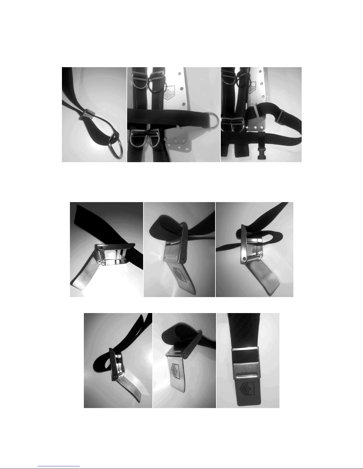
9) Let's move on to the assembly of the crotch strap. Insert a smooth plastic loop (Fig. 26)
and secure the strap by passing it through the proper slot in the backplate (Fig. 27-29).
Mount the male attach of quick release buckles and insert them into the corresponding
attachments on the belt as shown in the following pictures (Fig. 30) and (Fig. 31).
Be very careful to fit the buckles in the correct direction otherwise they will not
remain in the set position.
(Fig. 26) (Fig. 27) (Fig. 28)
(Fig. 29) (Fig. 30) (Fig. 31)
Page 17
Page17of34
Harness assembly, adjustable type
1) Insert the strap with the eyelet aligned in the upper back part of the backplate (Fig. 33)
and (Fig. 34).
(Fig. 32) (Fig. 33) (Fig. 34)
2) Run the strap through the upper horizontal slots of the backplate (Fig. 35) e (Fig. 36).
(Fig. 35) (Fig. 36)
Page 18

Page18of34
3) Insert a smooth loop and a "D" ring on the right belt (Fig. 37). Repeat the procedure on
the opposite side using the elastic accessory-holder ring (Fig. 38) and insert the elastic
band of retention of the control unit (Fig. 39).
(Fig. 37) (Fig. 38) (Fig. 39)
4) Insert a smooth loop and a "bent D" ring (Fig. 40) on both shoulder straps (Fig. 41);
add two more smooth loops (Fig. 42).
(Fig. 40) (Fig. 41) (Fig. 42)
Page 19

Page19of34
5) Insert a female attach of a quick release buckle onto the right shoulder strap (Fig. 43)
and slide it back into the smooth loop (Fig. 44) e (Fig. 45).
(Fig. 43) (Fig. 44) (Fig. 45)
6) Insert the remaining strap under a "bent D" ring on the right shoulder strap (Fig. 46) so
that it remains locked (Fig. 47). Repeat the same procedure on the left shoulder strap
(Fig. 43-48).
(Fig. 46) (Fig. 47) (Fig. 48)
Page 20
Page20of34
7) Insert a male attach of a quick release buckle onto the belt that connects the right
shoulder strap to the belt (Fig. 49) e (Fig. 50). Pull the strap back from the inside to the
outside of the backrest through the sloped outer slit (Fig. 51).
(Fig. 49) (Fig. 50) (Fig. 51)
8) Insert a toothed loop on the right belt (Fig. 52) and slide it from the outside to the
inside through the sloped outer slit of the backplate (Fig. 53) e (Fig. 54). Repeat the same
procedure on the opposite side (Fig. 49-54).
(Fig. 52) (Fig. 53) (Fig. 54)
Page 21
Page21of34
9) On the right belt end insert a smooth loop and a "D" ring about 15cm from the
backplate (Fig. 56) e (Fig. 57). Insert the female attach of a quick release buckle for the
right crotch strap and lock it with a plastic toothed loop (Fig. 58) and (Fig. 59).
(Fig. 55) (Fig. 56) (Fig. 57)
(Fig. 58) (Fig. 59)
Page 22
Page22of34
10) On the left belt end insert a smooth loop and a "D" ring about 15cm from the
backplate (Fig. 60) e (Fig. 61). Insert the female attach of a quick release buckle for the
left crotch strap (Fig. 62).
(Fig. 60) (Fig. 61) (Fig. 62)
11) Still on the left belt insert the metal buckle passing and passing the belt on the buckle
following the steps illustrated by the following pictures (Fig. 63-68).
(Fig. 63) (Fig. 64) (Fig. 65)
(Fig. 66) (Fig. 67) (Fig. 68)
Page 23
Page23of34
12) Let's move on to the assembly of the crotch strap.
Insert a smooth plastic loop (Fig. 69) and secure the strap by passing it through the
proper slot in the backplate (Fig. 70-72). Mount the male attach of quick release buckles
and insert them into the corresponding attachments on the belt as shown in the following
pictures (Fig. 73) e (Fig. 74) be very careful to fit the buckles in the correct
direction otherwise they will not remain in the set position.
(Fig. 69) (Fig. 70) (Fig. 71)
(Fig. 72) (Fig. 73) (Fig. 74)
Page 24
Page24of34
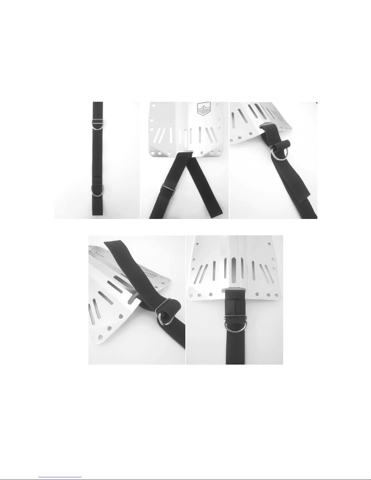
Assembly of the Single Crotch Strap
On the crotch strap terminal insert a smooth loop and a steel "D" ring (Fig. 75) and pass
the belt through the specific slot in the backplate (Fig. 76).
Insert the belt into the smooth steel loop (Fig. 77) again, fold it and reinsert it once again
into the smooth steel loop (Fig. 78). Fold the belt and fasten it with the supplied rubber
band (Fig. 79).
(Fig. 75) (Fig. 76) (Fig. 77)
(Fig. 78) (Fig. 79)
Page 25
Page25of34
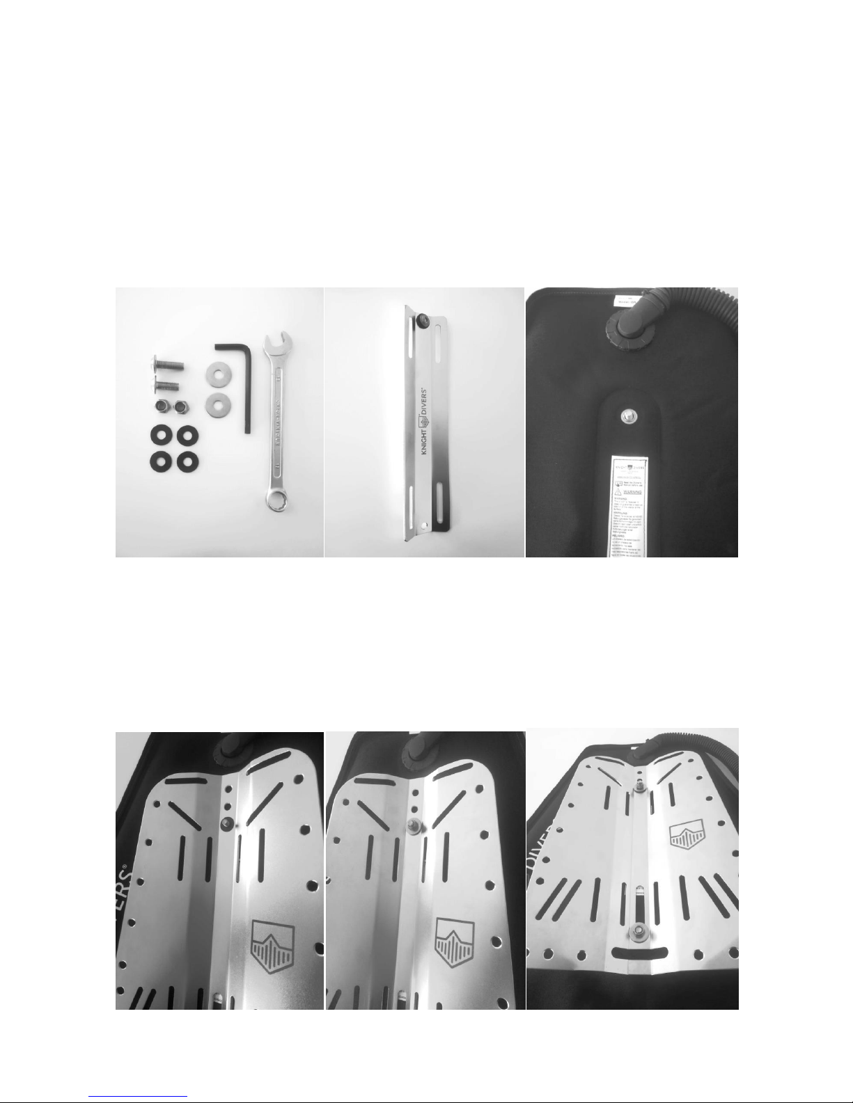
Assembly of the BCD with single cylinder adapter
(N.B. the operation should be performed only after having mounted the harness)
Stainless Steel Version
1) Get a 5 mm Allan Key and a 13 mm wrench (Fig. 80). Use only the material provided in
the assembly kit shown in (Fig. 80) (Long bolt, short bolt, 2 large washers, 2 self-locking
nuts and 4 smooth polyurethane washers)
2) Insert the polyurethane washer onto the long bolt and insert it into the upper hole of
the single-cylinder adapter (Fig. 81) and the Wing (Fig. 82).
(Fig. 80) (Fig. 81) (Fig. 82)
2) Insert the whole in the third hole of the backplate (N.B. pay attention to the
positioning in the correct hole otherwise the Wing will not work in an optimal way) and
apply the polyurethane washer (Fig. 83), then apply the steel washer and tighten the selflocking nut correctly (Fig. 84).
3) Repeat the procedure for the short bolt to be inserted in the lower hole (Fig. 85).
(Fig. 83) (Fig. 84) (Fig. 85)
Page 26

Page26of34
Alluminium version
1) Get a 5 mm Allan Key and a 13 mm wrench (Fig. 86). Use only the material provided in
the assembly kit shown in (Fig. 86) (Long bolt, short bolt, 2 small washers, 2 self-locking
nuts, 4 smooth polyurethane washers and 4 cordura washers).
2) Insert the polyurethane washer onto the long bolt and insert it into the upper hole of
the single-cylinder adapter (Fig. 87) then insert on the opposite side the cordura washer
(Fig. 88).
(Fig. 86) (Fig. 87) (Fig. 88)
2) Insert the whole into the upper hole of the wing (Fig. 89), the applied the cordura
washer (Fig. 90) and insert in the third hole of the backplate (N.B. pay attention to the
positioning in the correct hole otherwise the Wing will not work in an optimal way) and
apply the polyurethane washer (Fig. 91)
(Fig. 89) (Fig. 90) (Fig. 91)
Page 27

Page27of34
3) Apply the steel washer and tighten the self-locking nut correctly (Fig. 92).
4) Repeat the procedure for the short bolt to be inserted in the lower hole (Fig. 93)
(Fig. 92) (Fig. 93)
Example of correct backplate assembly and correct cylinder positioning for
steel versions (Fig. 94 - 95) and aluminium (Fig. 96 - 97)
(Fig. 94) (Fig. 95)
(Fig. 96) (Fig. 97)
Page 28

Page28of34
Assembly of the BCD with double tank
(N.B. the operation should be performed only after having mounted the harness)
1) Place the double tank on a floor with the outlets of the valve upwards; insert the
threaded pins with the free part upwards. (Fig. 98). Put the rear part of the bladder on the
double tank, taking care to insert the pins exactly into the stainless steel eyelets (Fig. 99).
(Fig. 98) (Fig. 99)
2) Place the metal backrest on the bladder inserting the threaded pins into the
appropriate holes and slot. insert the threaded pins in the third hole of the backplate
(N.B. pay attention to the positioning in the correct hole otherwise the Wing will not
work in an optimal way) (Fig. 100). Insert the washers on the threaded pins and lock
tightening the proper nuts (Fig. 101).
(Fig. 100) (Fig. 101)
Page 29

Page29of34
Example of correct backplate assembly and correct double tank positioning
(Fig. 102 - 103)
(Fig. 102) (Fig. 103)
PRE DIVE PREPARATION
The BCD is supplied as accessory with a low pressure hose (LP) with quick release
connection that provides low pressure air to the inflator. The hose must be connected in
one of the low pressure ports (LP) of your regulator.
WARNING :
Use only air to inflate the stabilizing jacket. The use of oxygen-enriched gas
may cause fire and explosion.
KNIGHT DIVERS Ltd always uses hoses certified according to EN 1809, EN 250 and EN
14225-2 standards, with working pressure up to 12 bars; the thread is the standard
3/8"UNF and the quick release can also be operated with thick gloves. The gas flow that
feeds the filling valve is abundant, no pressure drops occur even in conditions of intense
cold.
WARNING :
Never connect a low pressure (LP) hose to a high-pressure (HP) port of your
regulator. If a low pressure hose is connected to high-pressure, may stop
working without warning, causing serious injury to the person.
The first stages of the regulators have the low pressure ports (LP) smaller (3/8" X 24 UNF
thread) then the high pressure ports (HP) (7/16" X 20 UNF thread). In any case, it is
necessary to pay attention to the old regulators in which the HP and LP ports were all the
same. In most cases, the HP ports are marked HP. In any doubtful case, carefully check
output pressure. The maximum pressure of an LP port should be around 14 bars. Use a
common 4mm Allen wrench to remove the low pressure (LP) cap. Once it is localized the
low pressure port and has removed the plug, make sure the O-Ring is present on the hose
and in good condition. Also check the hose to make sure that the threads and O-Rings are
Page 30

Page30of34
free of dirt and debris. Install the threaded portion of the hose in the LP port using a
14mm wrench. Do not over tighten (exactly with a torque of 14.7 Nm).
WARNING :
If the hose supplied with your KNIGHT DIVERS BCD is bent, twisted or forced
when worn, the load valve may not work properly; replace it immediately with
a new hose KNIGHT DIVERS.
We advise you to follow our recommendations described here in order to avoid problems
during the dive.
Before every dive, verify that the rings nuts are firmly screwed on the inflator and the
valve; inflate completely the stabilizing jacket and wait at least 30 minutes to make sure
that it is kept expanded: if it is deflated, do not proceed to the dive before you fix the
problem.
The first step to be taken is to attach the BCD to the cylinder, positioning the cylinder with
the outlet valves facing you, insert the stabilizing jacket, maintaining the rear part of the
backrest in front of the valve. Tighten the band on the cylinder and close the special
buckles; secure any excess strap length using the special strips provided. By tightening
the band on the cylinder while dry you may notice loosening of tension when diving with
consequential slipping of the cylinder. We therefore recommend wetting the bands before
carrying out this operation.
If you use a double tank, follow the instructions on page 28.
Adjust the harness straps according to your size and sort of equipment used. Proper
adjustment will allow you maximum comfort, stability and safety.
At this point, put on the BCD and assume an erect position, lowering the nape of your
neck backwards: if your body position is correct, you should have no problem carrying out
this operation. At the same time, check that the base of the cylinder does not move
downwards excessively, disturbing your movements. We advise you to mark a fixed
reference point on the cylinder- for example, a strip of adhesive tape or painted line - so
that you can always re-assemble your BCD in the correct position.
Page 31

Page31of34
CAUTION :
The Optimal Position is obtained by fixing the cylinder to the BCD in such a way that
the valves are always placed above the upper edge of the Wing (Fig. 104-105) and that
the first stage of the regulator and the various hoses, of low and high pressure, do not
interfere with the free movement of the Wing.
(Fig. 104) (Fig. 105)
Remember that the attachment system is designed to assemble a single cylinder (with a
minimum diameter of 170mm and a maximum of 220mm). You can attach also twin
cylinders (maximum 12 + 12 with a minimum diameter of 170mm) with the appropriate
accessories.
After opening the cylinder valve, connect the quick release attach with the male connector
on the inflator taking between thumb and forefinger the collar of the quick release attach,
slide it back and press down firmly on the male connector of the inflator, then release the
collar. To disconnect the quick release attach simply slide back the collar and the hose will
release automatically.
Arrange the shoulder straps and the belts to the maximum expansion for easy donning.
Slide your arms through the shoulder straps taking care to leave over your shoulder all the
low and high pressure hoses. Inhale deeply and tightened the straps on the shoulders,
chest and abdomen, making it adheres well to the body so it does not hinder or impede
movement or cause any sensation of oppression. Attach the crotch strap to the belt and
proceed to wear the ballast belt.
Page 32

Page32of34
WARNING :
If you use a ballast belt, remember to place it above the crotch strap so that, in
an emergency, it can be quickly abandoned without getting caught in the
straps. Failure to observe this precaution could result in serious injury to the
diver.
Be careful, always partially deflate the stabilizing jacket before entering the water to
compensate for any additional weight.
Start the dive deflating the bag using:
Option 1 – put the inflator over your shoulders and press the exhaust button on the
top (slow discharge)
Option 2 – upside down, pull the knob on the cord of the pressure relief valve
(rapid discharge).
Once you start the descent, the speed tends to increase: short bursts of load button
allows you to adjust it. To the desired depth, by the load button, always established
neutral buoyancy with small inputs and calibrated air.
During the ascent, maintain a slightly negative attitude to earn the surface.
WARNING :
Improper use of the inflator can cause you to lose rapidly buoyancy and uncontrolled
ascents and descents, with serious consequences. In surface inflate the stabilizing jacket
to have a positive attitude; to undress the jacket open or loosen the abdominal buckle and
the crotch strap.
WARNING :
The stabilizing jacket is used to compensate underwater trim, cannot be used to lift heavy
objects from the bottom since this could cause uncontrolled ascents with serious
consequences.
Page 33

Page33of34
MAINTENANCE ROUTINE
All KNIGHT DIVERS BCD are manufactured and individually tested with strict criteria of
quality control. The proper maintenance of your stabilizing jacket will be extremely useful
to extend its life.
When you finish diving for the day, rinse thoroughly with fresh water both the external
and the internal face. To do this, enter the fresh water through the drain button air of the
inflator, then flip the jacket and empty it by pressing the same exhaust button. Rinse
carefully the drain and load valves. Dry the valves with compressed air after rinsing. Let
the jacket dry in the shade. Do not put the jacket with objects that could puncture or
damage the bladder, avoid contact with solvents, oils, gasoline. Put the jacket perfectly
dry, partially inflated, in a cool and airy place. Pay particular attention to the valves.
WARNING :
The valves of the stabilizing jacket must be cleaned after each use exactly as
your regulator. The load valve may be sticky due to the accumulation of salt.
The exhaust valves may be clogged due to deposits of salt or limestone inside
the mechanism.
CAUTION :
Do not hang your stabilizing jacket in full sun.
STORAGE OF THE STABILIZING JACKET
Proper storage will extend the life of your stabilizing jacket. Keep it in a cool, dry place
and away from direct sunlight. The place of storage should be free of ozone generators,
such as electrical machinery or gas.
The User Manual for Knight Divers BCD can be downloaded from
www.knightdivers.eu
WARRANTY
All KNIGHT DIVERS BCD are covered by a 2 year warranty period against manufacturing
defects.
Page 34
Page34of34
 Loading...