

Knick Stratos Pro A4..MSPH series, Stratos Pro A411N-MSPH, Stratos Pro A401N-MSPH Instruction Manual

www.knick.de
Latest Product Information:
Stratos®Pro A4... MSPH
Instruction Manual

2
Warranty
Warranty
Defects occurring within 3 years from delivery date shall be remedied
free of charge at our plant (carriage and insurance paid by sender).
Sensors, ttings, and accessories: 1 year.
Subject to change without notice.
Return of Products Under Warranty
Please contact our Service Team before returning a defective device.
Ship the cleaned device to the address you have been given.
If the device has been in contact with process uids, it must be
decontaminated/disinfected before shipment. In that case, please
attach a corresponding certi cate, for the health and safety of our
service personnel.
Disposal
Please observe the applicable local or national regulations concerning
the disposal of “waste electrical and electronic equipment”.

3
Documents Supplied
Stratos® Pro A411/A211 pH
QuickStart
Other languages: www.knick.de
Short Instructions ............................3
Kurzübersicht .................................15
Quick Start ......................................27
Быстрый старт .............................. 39
Inicio rápido ...................................51
Início rápido ...................................63
快速启动 ........................................75
CD-ROM
Complete documentation:
• Instruction manuals
• Safety instructions
• Short instructions
Safety Information
In o cial EU languages and others.
• ATEX / IECEX / FM / CSA
• EC Declarations of Conformity
Short Instructions
In German, English, French, Russian,
Spanish, Portuguese, Swedish, and Dutch.
More languages on CD-ROM and
on our website: www.knick.de
• Installation and commissioning
• Operation
• Menu structure
• Calibration
• Error messages and recommended actions
Stratos® Pro Series
Safety Instructions
www.knick.de
Speci c Test Report

4
Contents
Documents Supplied ..................................................................... 3
Introduction .................................................................................... 7
Intended Use ....................................................................................................7
Safety Information ......................................................................... 8
Safety Precautions for Installation ...........................................................9
Registered Trademarks ................................................................................. 9
Overview of Stratos Pro A4... MSPH..........................................10
Assembly ........................................................................................ 11
Package Contents .........................................................................................11
Mounting Plan, Dimensions .....................................................................12
Pipe Mounting, Protective Hood ............................................................13
Panel Mounting .............................................................................................14
Installation ..................................................................................... 15
Installation Instructions .............................................................................15
Rating Plates / Terminal Assignments...................................................16
Power Supply, Signal Lines .......................................................................17
Sensor Connection ......................................................................................18
Wiring Examples ...........................................................................................19
Protective Wiring of Relay Contacts ......................................................22
User Interface, Keypad ................................................................24
Display ............................................................................................ 25
Signal Colors (Display Backlighting) ......................................................25
Measuring Mode...........................................................................26
Selecting the Mode / Entering Values ......................................27
Operating Modes ..........................................................................28
Menu Structure of Modes and Functions ............................................29
HOLD Mode ....................................................................................................30
Alarm .................................................................................................................31
Configuration ................................................................................32
Menu Structure of Configuration ...........................................................32

5
Contents
Parameter Set Selection ..............................................................34
Parameter Set A/B ........................................................................................34
Configuration ................................................................................35
Configuration (Original for Copy) ...........................................................39
Sensor ...............................................................................................................42
Current Output 1 ..........................................................................................50
Current Output 2 ..........................................................................................56
Temperature Compensation ....................................................................58
Alarm .................................................................................................................60
Limit Function ................................................................................................62
Pulse Length / Pulse Frequency Controller.........................................71
Controller .......................................................................................................72
WASH Contact ...............................................................................................76
Time and Date ...............................................................................................78
Tag Number ...................................................................................................78
Digital Sensors ..............................................................................80
Operation ........................................................................................................80
Connecting a Digital Sensor .....................................................................81
Sensor Replacement ...................................................................................82
Calibration .....................................................................................84
Selecting a Calibration Mode ..................................................................85
Zero Adjustment (ISFET) ............................................................................86
Automatic Calibration (Calimatic) ..........................................................88
Manual Calibration with Buffer Entry ...................................................90
Data Entry of Premeasured Sensors ......................................................92
Product Calibration (pH) ............................................................................94
ORP ( Redox) Calibration ...........................................................................96
Temp Probe Adjustment ............................................................................98
Measurement ................................................................................99
Diagnostics ..................................................................................101
Service ..........................................................................................106
Operating States .........................................................................110

6
Contents
Product Line and Accessories ..................................................112
Specifications ..............................................................................113
Buffer Tables ................................................................................120
-U1- Specifiable Buffer Set .....................................................................129
Error Handling .............................................................................132
Error Messages ............................................................................133
Sensoface .....................................................................................136
FDA 21 CFR Part 11 ....................................................................139
Electronic Signature – Passcodes ........................................................139
Audit Trail ..................................................................................................... 139
Index .............................................................................................140
Passcodes .....................................................................................148

7
Introduction
Intended Use
The Stratos Pro A4... MSPH is used for pH/mV, ORP, and temperature
measurement in industry, environment, food processing, and sewage
treatment.
The sturdy molded enclosure can be xed into a control panel or
mounted on a wall or at a post. The protective hood, which is available as accessory, provides additional protection against direct
weather exposure and mechanical damage.
The device has been designed for digital sensors.
Plain-text messages in a large, backlit display allow intuitive operation. The colored display backlighting signals alarm messages (red) or
HOLD mode (orange).
The “Sensocheck“ automatic monitoring of glass and reference electrode and the “Sensoface“ function for clear indication of the sensor
condition provide excellent diagnostics. The internal logbook (TAN
SW-A002) can handle up to 100 entries – up to 200 with AuditTrail
(TAN SW-A003).
The device provides two parameter sets which can be switched
manually or via a control input for di erent process adaptations or
di erent process conditions (e.g. beer and CIP).
Password protection for granting access rights during operation can
be con gured.
Two oating, digital control inputs (“Hold“ and “Control“) are available
for external control.
The internal PID process controller can be con gured as pulse length
or pulse frequency controller.
The device provides two current outputs (for transmission of measured value and temperature, for example) and four oating relay
contacts. A time-controlled cleaning function can be con gured.
Current is provided through a universal power supply 24 ... 230 V AC/
DC, AC: 45 ... 65 Hz.
Approvals for Measurement in Hazardous Locations:
Stratos Pro A4...B MSPH: acc. to FM and CSA in Class I Div 2 / Zone 2

8
Safety Information
Safety information –
Be sure to read and observe the following instructions!
The device has been manufactured using state of the art technology
and it complies with applicable safety regulations.
When operating the device, certain conditions may nevertheless lead
to danger for the operator or damage to the device.
See also separate document:
“Safety Instructions“. •
(EC Declaration of Conformity, FM, CSA Certi cates)
CAUTION!
Please note:
Before commissioning it must be proved that the device may be connected with other equipment.
Commissioning must only be performed by trained personnel authorized by the operating company! Whenever it is likely that protection
has been impaired, the device shall be made inoperative and secured
against unintended operation.
The protection is likely to be impaired if, for example:
the device shows visible damage•
the device fails to perform the intended measurements•
after prolonged storage at temperatures above 70°C•
after severe transport stresses•
Before recommissioning the device, a professional routine test must
be performed. This test must be carried out at the manufacturer's factory.

9
Safety Information
Safety Precautions for Installation
The • electrical installation shall conform to the national regulations
for electrical installations and/or other applicable national or local
codes or regulations.
The power supply shall be disconnectable from the device by a •
two-poled circuit breaker.
Switch and circuit breaker shall be located in close proximity to the •
equipment and be easily accessible by the OPERATOR.
They shall be marked as disconnect switch for the device.
Be sure to disconnect the mains supply and any relay contacts •
which are connected to separate current sources before starting
maintenance operations.
Approvals for Application in Hazardous Locations
Stratos Pro A4...B MSPH: acc. to FM and CSA in Class I Div 2 / Zone 2
Terminals:
Screw terminal, suitable for single wires / exible leads up to 2.5 mm
2
(AWG 14).
Recommended torque for the terminal screws: 0,5 ... 0,6 Nm.
Further Information on Installation in Hazardous
Locations:
See also separate “Safety Instructions“ document.
Registered Trademarks
The following names are registered trademarks. For practical reasons
they are shown without trademark symbol in this manual.
Stratos
®
Sensocheck
®
Sensoface
®
Calimatic
®
GainCheck
®
InPro® is a registered trademark of Mettler-Toledo.
HART® is a registered trademark of the HART Communication
Foundation.
10
Overview
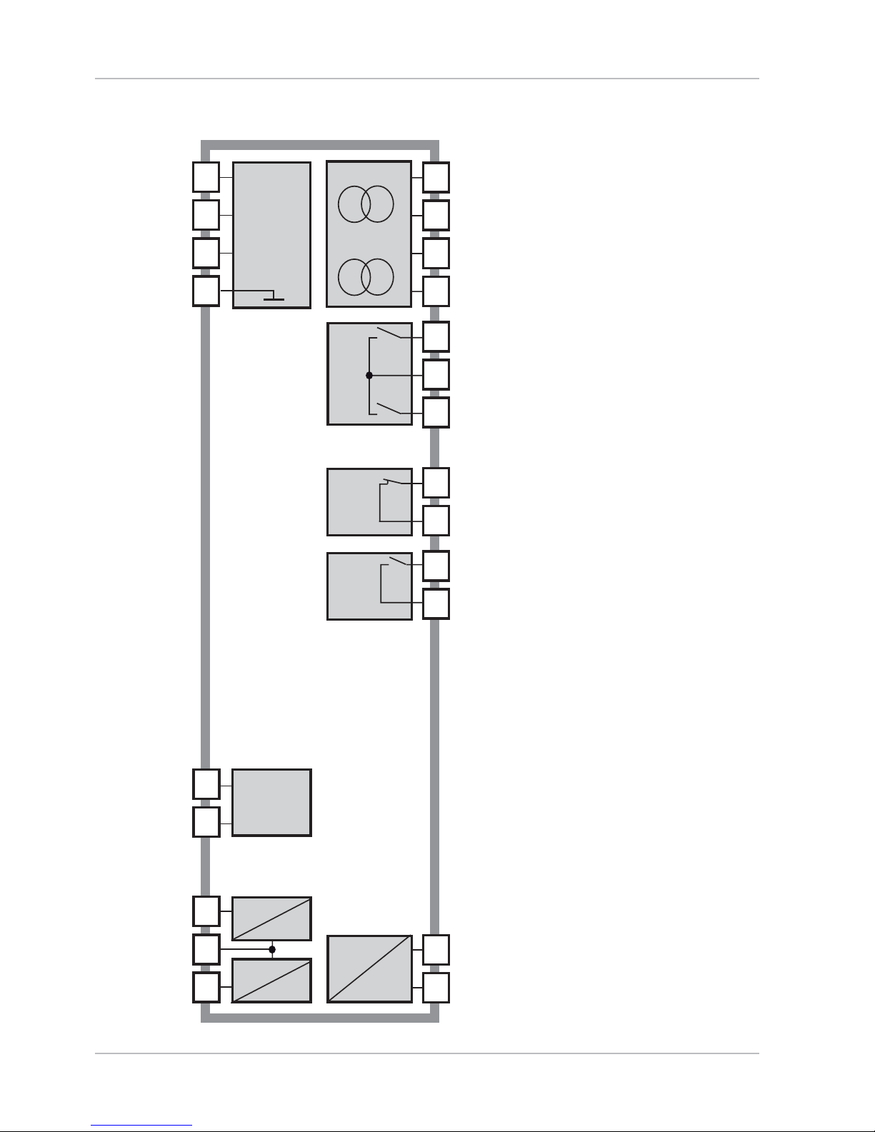
Overview of Stratos Pro A4... MSPH
7
8
14
15
16
17
18
19
20
21
22
10
9
5
6
11
12
13
Output 1
Input +
Input –
HOLD
HOLD /
CONTROL
CONTROL
+ Output 1 / HART
– Output 1 / HART
+ Output 2
– Output 2
REL 1
REL 2
REL 1/2
Alarm
Alarm
Wash
Wash
Power
Power
HOLD
Input
Input
Control
Output 2
R1
R2
Alarm
R3
R4
Wash
Power
1
2
3
4
RS 485
Power supply
RS 485 A
RS 485 B
GND/Shield

11
Assembly
Package Contents
Check the shipment for transport damage and completeness!
The package should contain:
Front unit, rear unit, bag containing small parts•
Specific t
est r
eport•
Documentation (cf Pg 3)•
CD-ROM•
Fig.: Assembling the enclosure
Jumper (3 x)1)
W
asher (1 x), f
or conduit 2)
mounting: Place washer
between enclosure and nut
Cable tie (3 x)3)
Hinge pin (1 x), insertable 4)
from either side
Enclosure screw (4 x)5)
Sealing insert (1 x)6)
Rubber reducer (1 x)7)
Cable gland (3 x)8)
Filler plug (3 x)9)
Hexagon nut (5 x)10)
Sealing plug (2 x), for sealing 11)
in case of wall mounting
11
10
9
8
76 5
4
1
2
3
12
Assembly
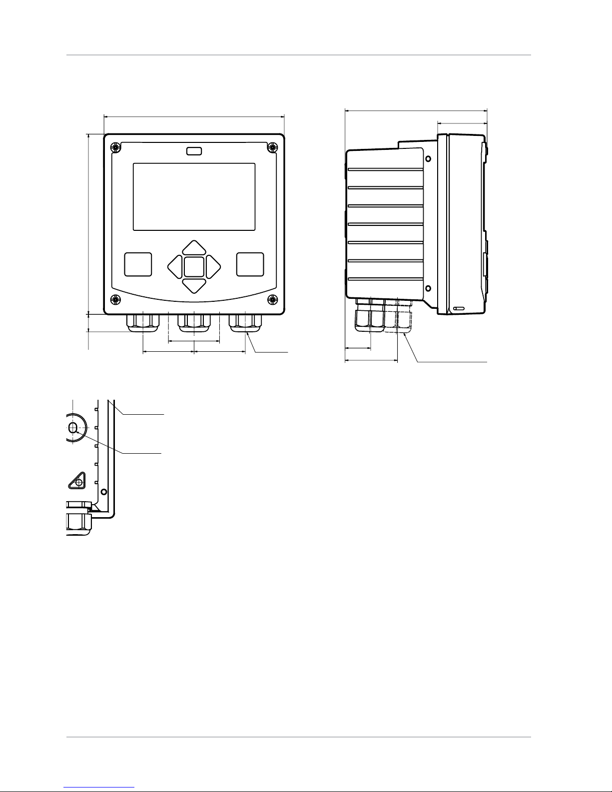
Mounting Plan, Dimensions
Fig.: Mounting plan (All dimensions in mm!)
Cable gland (3 x)1)
Knockouts for cable gland or 2)
½" conduit,
21.5 mm dia. (2 knockouts)
Conduits not included!
Knockout for pipe mounting 3)
(4 x)
Knockout for wall mounting 4)
(2 x)
148
148
42
42
42
14
117
41
21
43
1
2
34
80
74
6,2
4
3
13
Assembly
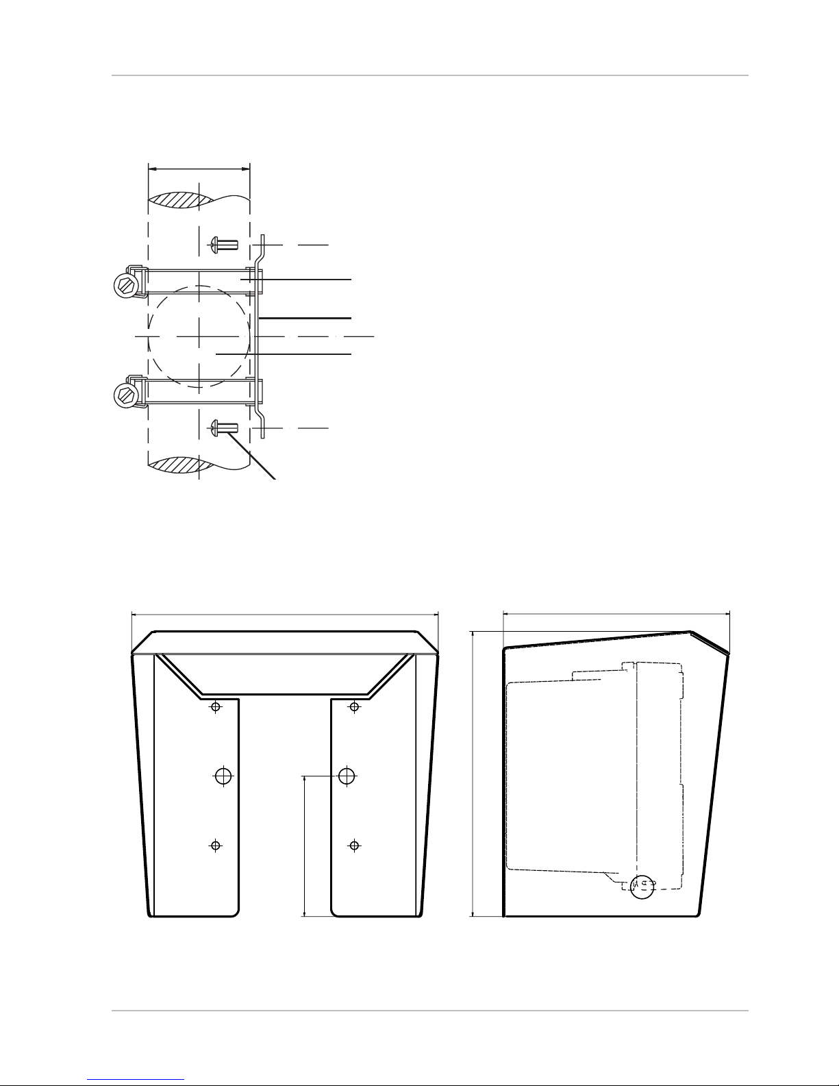
Pipe Mounting, Protective Hood
Fig.: ZU 0737 protective hood for wall and pipe mounting
(All dimensions in mm!)
Fig.: ZU 0274 pipe-mount kit (All dimensions in mm!)
147199
91
185
1
2
3
4
Hose clamp with worm gear 1)
drive to DIN 3017 (2 x)
Pipe-mount plate (1 x)2)
For vertical or horizontal posts 3)
or pipes
Self-tapping screw (4 x)4)
ø40...ø60

14
Assembly
Panel Mounting
Fig.: ZU 0738 panel-mount kit (All dimensions in mm!)
Circumferential sealing 1)
(1 x)
S
cr
ew (4 x)2)
Position of control panel3)
Span piece (4 x)4)
Threaded sleeve (4 x)5)
Cutout
138 x 138 mm (DIN 43700)
<30 76 31
1...22
1
2345

15
Installation
Installation Instructions
Installation of the device must be carried out by trained experts in •
accordance with this instruction manual and as per applicable local
and national codes.
Be sure to observe the technical speci cations and input ratings •
during installation!
Be sure not to notch the conductor when stripping the insulation!•
Before connecting the device to the power supply, make sure that •
its voltage lies within the range 24 to 230 V AC/DC!
The supplied current must be galvanically isolated. •
If not, connect an isolator module.
All parameters must be set by a system administrator prior to •
commissioning!
Terminals:
suitable for single wires / exible leads up to 2.5 mm
2
(AWG 14)
Additional safety precautions have to be taken for operation
in hazardous locations
FM, CSA Cl. I Div 2 /
Zone 2!
(See separate “Safety Instructions“ document.)

16
Installation
Rating Plates / Terminal Assignments
Fig.: Terminal assignments of Stratos Pro A4...
Fig.: Stratos Pro A401N-MSPH rating plate at bottom of front
Fig.: Stratos Pro A411N-MSPH rating plate at bottom of front

17
Power Supply, Signal Lines
Connect the power supply for Stratos Pro A401/A411 MSPH
to terminals 21 and 22.
(24 ... 230 V AC, 45 ... 65 Hz / 24 ... 80 V DC)
Assignments
1 (BN) Power suppy
2 (GN) RS 485 A
3 (YE) RS 485 B
4 (WH) GND/shield
5 + input
6 – input
7 + out 2
8 – out 2
9 + out 1/HART
10 – out 1/HART
11 hold
12 hold/control
13 control
14 REL 1
15 REL 1/2
16 REL 2
17 alarm
18 alarm
19 wash
20 wash
21 power
22 power
Fig.: Terminals, device opened, back of front unit
Areas for placing the
screwdriver to pull out
the terminals
122

18
Connect the sensor lines with the sensor connection
(RS-485, terminals A...K).
Sensor Connection
Sensor connection
RS-485
Areas for placing the
screwdriver to pull out
the terminals
122
Fig.: Terminals, device opened, back of front unit
19
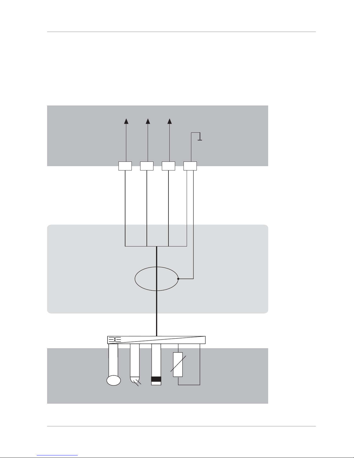
Wiring Examples
Example 1:
Measuring task: pH/ORP, temp, glass impedance, ref. impedance
Sensors ( example): SE 533/1-ADIN (Knick)
Cable (example): CA/003-NAADIN11 (Knick)
Sensor(s) Cable Device
1 2 3 4
3,3 V
RS 485 (A)
RS 485 (B)
GND/shield
Yellow
White/Clear
Shield (blue)
Brown
Green

20

21
1 2 3 4
3,3 V
RS 485 (A)
RS 485 (B)
GND/shield
Wiring Examples
Example 2:
Measuring task: pH/ORP, temp, glass impedance
Sensors (example): SE531/1-NMSN (Knick)
Yellow
White
Shield (clear)
Brown
Green
Sensor(s) Cable Device
22
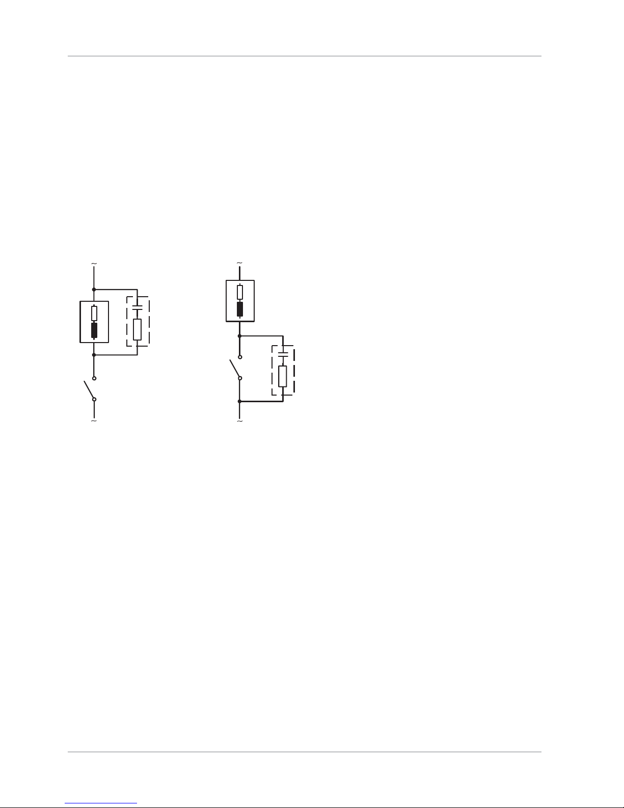
Protective Wiring of Relay Contacts
Protective Wiring of Relay Contacts
Relay contacts are subject to electrical erosion. Especially with
inductive and capacitive loads, the service life of the contacts will be
reduced. For suppression of sparks and arcing, components such as RC
combinations, nonlinear resistors, series resistors, and diodes should
be used.
Typical AC applications
with inductive load
Load1
RC combination,2
e.g. RIFA PMR 209
Typical RC combinations for
230 V AC:
capacitor 0.1 µF / 630 V,
resistor 100 Ω / 1 W
Contact3
1
2
3
1
2
3
23
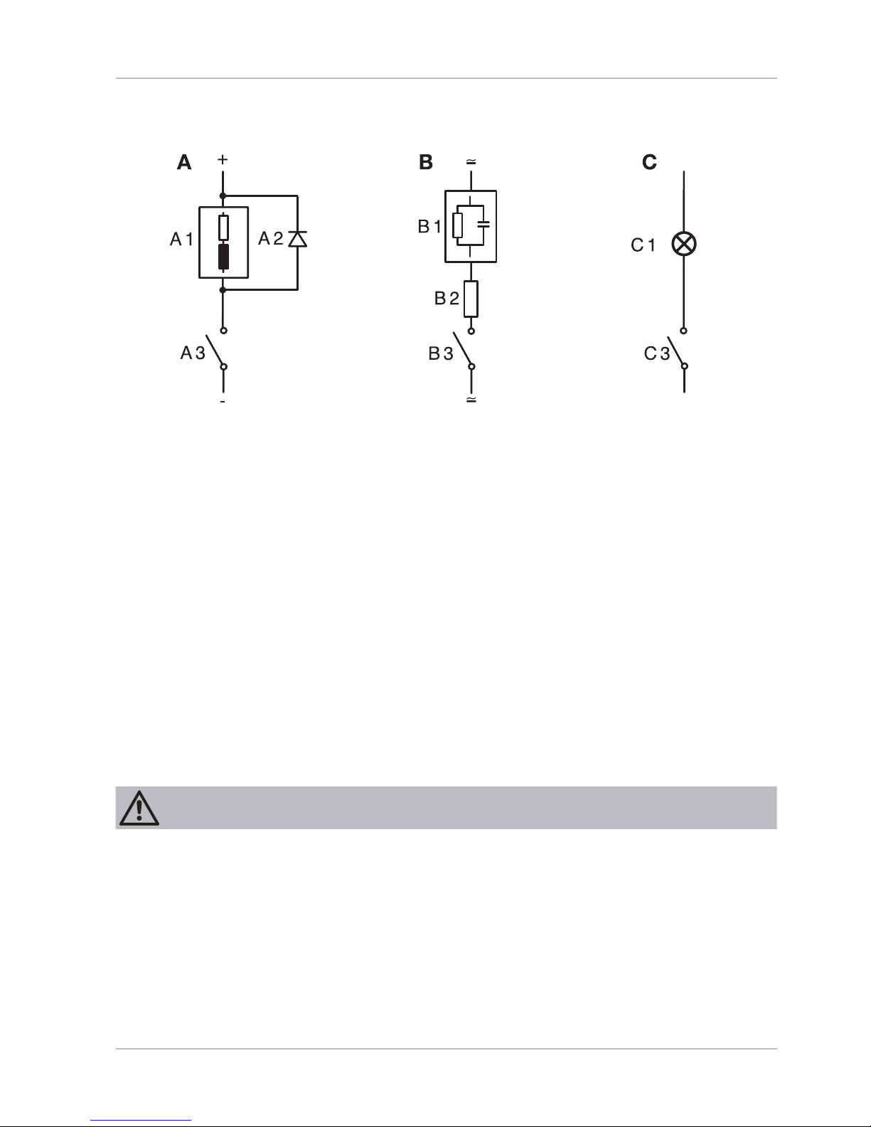
Protective Wiring of Relay Contacts
A: DC application with inductive load
B: AC/DC applications with capacitive load
C: Connection of incandescent lamps
A1 Inductive load
A2 Free-wheeling diode, e.g. 1N4007 (Observe polarity)
A3 Contact
B1 Capacitive load
B2 Resistor, e.g. 8 Ω / 1 W at 24 V / 0.3 A
B3 Contact
C1 Incandescent lamp, max 60 W / 230 V, 30 W / 115 V
C3 Contact
Make sure that the maximum ratings of the relay contacts are not
exceeded even during switching!
Typical Protective Wiring Measures
WARNING!
24
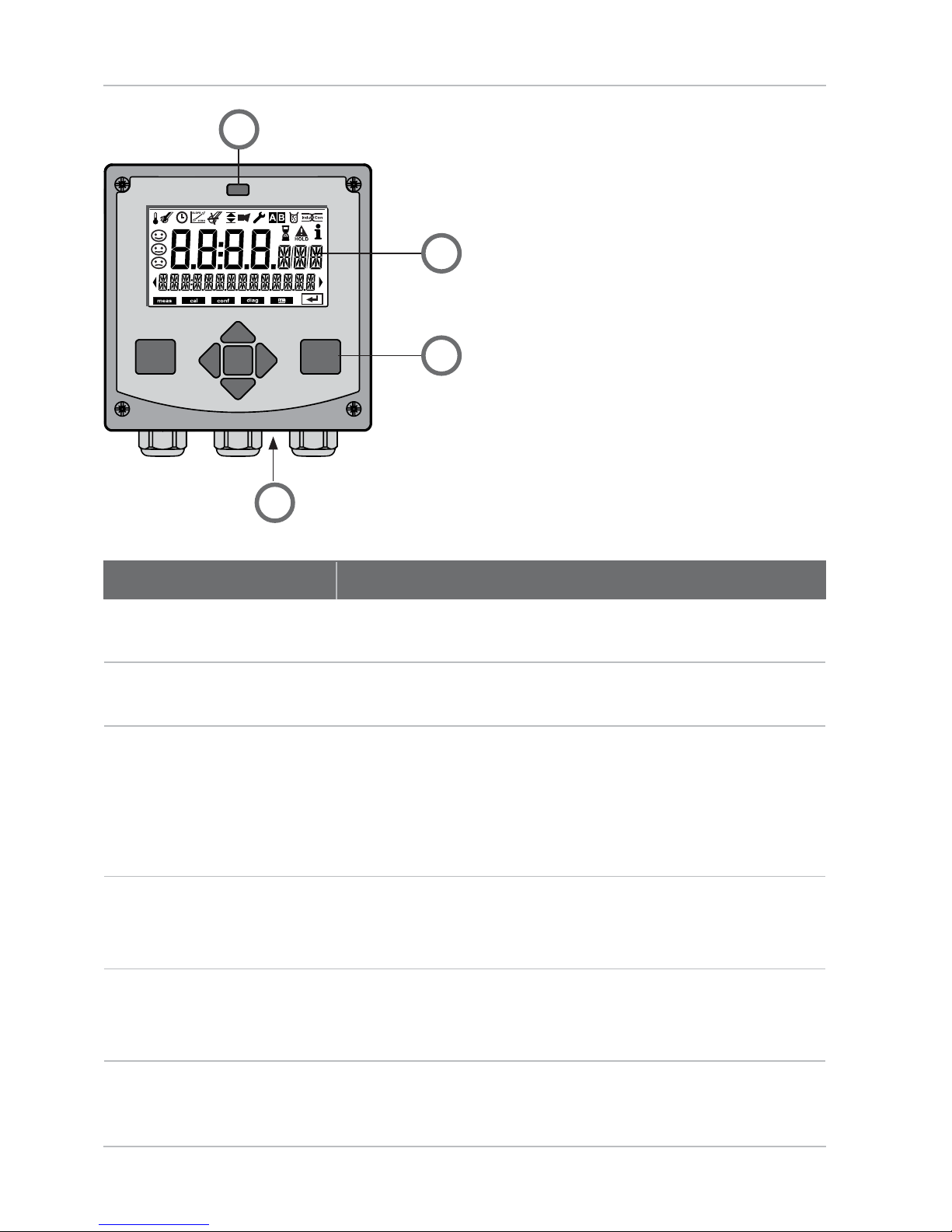
User Interface, Keypad
1 IrDA transmitter/receiver
2 Display
3 Keypad
4 Rating plate (bottom)
Key Function
meas Return to last menu level•
Directly to measuring mode (press > 2 s)•
info Retrieve information•
Show error messages•
enter Con guration: Con rm entries, •
next con guration step
Calibration:•
Continue program ow
Measuring mode: Display output current•
Arrow keys
up / down
Measuring mode: Call menu•
Menu: Increase/decrease a numeral•
Menu: Selection•
Arrow keys
left / right
Measuring mode: Call menu•
Menu: Previous/next menu group•
Number entry: Move between digits•
1
3
4
2
25
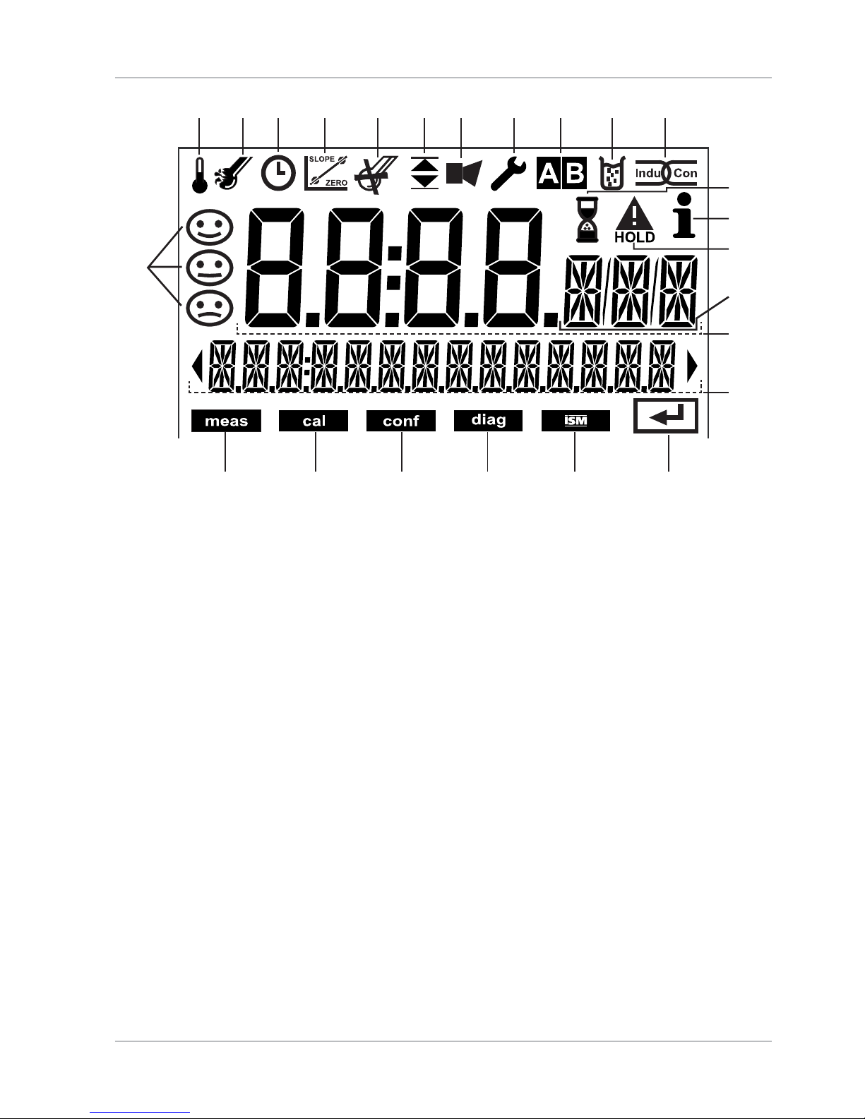
Display
1 Temperature
2 Sensocheck
3 Interval/response time
4 Sensor data
5 Digital sensor devaluated
6 Limit values
7 Alarm
8 Service
9 Parameter sets A/B
10 Calibration
11 Digital sensor
12 Waiting time running
13 Info available
14 HOLD mode active
15 Main display
16 Secondary display
17 Proceed with enter
18 Digital sensor
19 Diagnostics
20 Con guration mode
21 Calibration mode
22 Measuring mode
23 Sensoface
24 Measurement symbol
1234 5 67 891011
171819202122
12
13
14
15
16
23
24
Signal Colors ( Display Backlighting)
Red Alarm
Orange HOLD mode (Calibration, Con guration, Service)
Turquoise Diagnostics
Green Info
Purple Sensoface message

26
Measuring Mode
After the operating voltage has been connected, the device automatically goes to “Measuring“ mode. To call the measuring mode
from another operating mode (e.g. Diagnostics, Service):
Hold meas key depressed (> 2 s).
Process
variable
Temperature
Sensoface indicator
(sensor status)
Time
Mode indicator
(measuring)
Active
parameter set
enter key
In measuring mode the display indicates:
Measured value and time (24/12 h AM/PM) as well as temperature •
in °C or °F (formats selected during con guration)
By pressing the meas key in measuring mode you can view the
following displays (for approx. 60 sec):
Measured value and selection of parameter set A/B •
(if set to “Manual“)
Measured value and tag (point of measurement designation – •
entered during con guration)
Time and date•
Controller (if con gured), upper display: controller output Y,•
lower display: setpoint
Pressing the enter key shows the output currents. They are displayed
as long as enter is held depressed, then the measured-value display
will return after 3 sec.
The device must be con gured for the respective
measurement task!
Hold meas key
depressed to call the
measuring mode
(pressing once more
switches the display)

27
Selecting the Mode / Entering Values
To enter a value:
Select numeral: left / right arrow key5)
Change numeral: up / down arrow key6)
Con rm entry with 7) enter
To select the operating mode:
Hold 1) meas key depressed (> 2 s) (measuring mode)
Press any arrow key: the selection menu appears2)
Select operating mode using left / right arrow key3)
Press 4) enter to con rm the selected mode
Selection menu
Selected mode
(blinks)
1
2
3
4
5
6
7

28
Diagnostics
Display of calibration data, display of sensor data, performing a device
self-test, viewing the logbook entries, display of hardware/software versions of the individual components. The logbook can store 100 events
(00...99). They can be displayed directly on the device. The logbook can
be extended to 200 entries using a TAN (Option).
HOLD
Manual activation of HOLD mode, e.g. for replacing a digital sensor. The
signal outputs adopt a de ned state.
Calibration
Every sensor has typical characteristic values, which change in the
course of the operating time. Calibration is required to supply a correct measured value. The device checks which value the sensor delivers
when measuring in a known solution. When there is a deviation, the device can be “adjusted“. In that case, the device displays the “actual“ value
and internally corrects the measurement error of the sensor. Calibration
must be repeated at regular intervals. The time between the calibration
cycles depends on the load on the sensor. During calibration the device
is in HOLD mode.
During calibration the analyzer remains in the HOLD mode until it is
stopped by the operator.
Con guration
The analyzer must be con gured for the respective measurement
task. In the “Con guration“ mode you select the connected sensor, the
measuring range to be transmitted, and the conditions for warning and
alarm messages. During con guration the device is in HOLD mode.
Con guration mode is automatically exited 20 minutes after the last
keystroke. The device returns to measuring mode.
Service
Maintenance functions (current source, relay test, controller test)
, IrDA
operation, passcode assignment, reset to factory settings, enabling of
options (TAN).
Operating Modes

29
Menu Structure of Modes and Functions
Measuring
mode
TAG display
Manual activation of HOLD mode, e.g. for sensor replacement.
The signal outputs behave as configured (e.g. last measured value, 21 mA)
pH adjustment (as configured)
ORP adjustment
Product calibration
Z
er
o adjustment (for ISFET only)
Adjustment of temperature probe
Configuring parameter set A
Configuring parameter set B
Display of measured values for validation (simulators)
Current source, output 1
Curr
ent source, output 2
Relay test
C
ontr
oller: manual speci cation of controller output
Activating the IrDA interface
Specifying access codes for operating modes
Reset to factory setting
Enabling an option via TAN
Pressing any arrow key opens the selection menu.
S
elec
t the menu group using the left/right arrow keys.
Press enter to open a menu. Press meas to return.
(Access via
code, factory
setting:
5555)
meas
Controller
parameter display
(if configured)
meas
meas
after 60 s after 60 s
Display of calibration data
Display of sensor data
Self test: RAM, ROM, EEPROM, module
100 ev
ents with dat
e and time
Display of measured values (mV_pH, mV_ORP, RTD,
resistances of glass electrode, reference electrode)
Display of software version, model designation, serial number
CLK display
meas

30
HOLD Mode
The HOLD mode is a safety state during con guration and calibration.
Output current is frozen (Last) or set to a xed value (Fix).
Alarm and limit contacts are disabled.
The HOLD mode is indicated by orange display backlighting.
Terminating the HOLD Mode
The HOLD mode is ended by switching to measuring mode (hold
meas key depressed). The display reads “Good Bye“, after that, the
HOLD mode is exited.
When the calibration mode is exited, a con rmation prompt
ensures that the installation is ready for operation
(e.g.: sensor reinstalled, located in process).
HOLD mode, display icon:
HOLD active
21
4
HOLD active
Output current
[mA]
Output signal HOLD
Setting FIX = 21.0 mA
Output signal HOLD
Setting LAST
Output Signal During HOLD:
Output Signal Response
Last:• The output current is frozen at its last value. Recommended
for short con guration procedures. The process should not change
decisively during con guration. Changes are not noticed with this
setting!
Fix:• The output current is set to a value that is noticeably di erent
from the process value to signal the control system that the device
is being worked at.

31
Alarm
Manual Activation of HOLD
The HOLD can be activated manually from the HOLD menu.
This allows checking or replacing a sensor, for example, without
provoking unintended reactions of outputs or contacts.
Press meas key to return to selection menu.
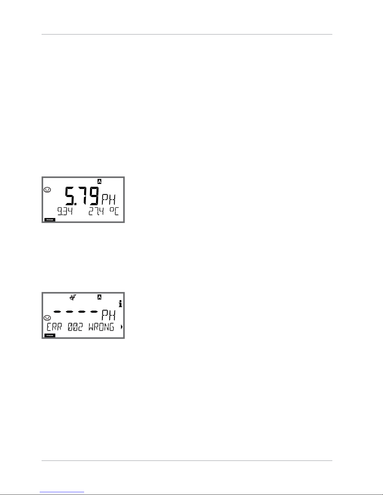
Alarm
When an error has occurred, Err xx is displayed immediately.
Only after expiry of a user-de ned delay time will the alarm be
registered and entered in the logbook.
During an alarm the display blinks, the display backlighting turns red.
Error messages can also be signaled by a 22 mA output current
(see Con guration).
The alarm contact is activated by alarm and power failure, see also
“Con guration / Alarm Settings“.
2 sec after the failure event is corrected, the alarm status will be
deleted.
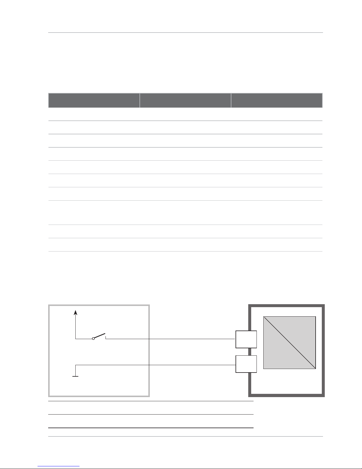
External Activation of HOLD
The HOLD mode can be activated from outside by sending a signal to
the Hold input (e.g. from the process control system).
10
11
Process control system
Power supply
12...24 V AC/DC
Stratos Pro A4...
Input
HOLD
HOLD inactive 0...2 V AC/DC
HOLD active 10...30 V AC/DC

32
enter
enter
enter
enter
Select menu
group
Menu group Code Display
Select menu
item
Sensor selection SNS:
Menu item 1
...
Menu item ...
Current output 1 OT1:
Current output 2 OT2:
Compensation COR:
Alarm mode ALA:
Relay outputs REL:
Cleaning WSH:
Setting the clock CLK:
Tag number TAG:
Configuration
Menu Structure of Con guration
The device provides 2 parameter sets “A“ and “B“. By switching between the parameter sets you can adapt the device to different measurement situations, for example.
Parameter set “B“ only permits setting of process-related parameters.
The configuration steps are assigned to different menu groups.
Using and you can jump between the individual menu groups.
Each menu group contains menu items for setting the parameters.
Pressing enter opens a menu item.
The values are edited using and . Pressing enter confirms/stores the settings.
Return to measurement: Press meas.
33
Con guration
Parameter Set A/B: Con gurable Menu Groups
(Some parameters are identical in A and B. They are con gured in
parameter set A only.)
Menu group Parameter set A Parameter set B
SENSOR Sensor selection --OUT1 Current output 1 Current output 1
OUT2 Current output 2 Current output 2
CORRECTION Compensation Compensation
ALARM Alarm mode Alarm mode
REL 1/REL 2 Relay outputs Relay outputs
WASH Cleaning --PARSET Parameter set
selection
---
CLOCK Setting the clock --TAG Tag number ---
External Switchover of Parameter Sets A/B
You can switch between parameter sets A and B by applying a signal
to the CONTROL input. For parameter setting, see Pg 38.
12
13
e.g. process control system
Max. 30 V AC/DC
Stratos Pro A4...
input
Control
Parameter set A active 0...2 V AC/DC
Parameter set B active 10...30 V AC/DC

34
19
20
Parameter Set A/B
Manual Selection. Signaling via WASH Contact.
Display Action Remark
To switch between
parameter sets:
Press meas
Manual selection of
parameter sets must have
been preset in CONFIG
mode. Default setting is a
fixed parameter set A.
Wrong settings change
the measurement properties!
PARSET blinks in the
lower line.
Select parameter set
using and keys
Select
PARSET A / PARSET B
Con rm with enter
Cancel with meas
The active parameter set can be
displayed using the WASH contact:
If con gured correspondingly,
the WASH contact signals:
“Parameter set A“ (open contact)
“Parameter set B“ (closed contact)
Wash
W
ash
R4
Wash
Parameter Set Selection

35
Configuration
Con guration Choices Default
Sensor (SENSOR)
SNS: MEMOSENS
INDUCON
MEMOSENS
TEMP UNIT °C / °F °C
TEMP MEAS AUTO
MAN
EXT
(only if enabled via
TAN)
AUTO
MAN –20...200 °C
(–4...392 °F)
025.0 °C
(077.0 °F)
TEMP CAL AUTO
MAN
EXT
(only if enabled via
TAN)
AUTO
MAN –20...200 °C
(–4...392 °F)
025.0 °C
(077.0 °F)
CAL MODE AUTO, MAN, DAT AUTO
AUTO
BUFFER SET
-00-...-09-, -U1Please note:
Pressing info displays
nominal buffer values
and manufacturers
-00-
U1
(For specifiable
buffer set,
see Appendix:
“Buffer Tables“)
EDIT BUFFER 1 (NO, YES) NO
Enter values for buffer 1
EDIT BUFFER 2 (NO, YES) NO
Enter values for buffer 2
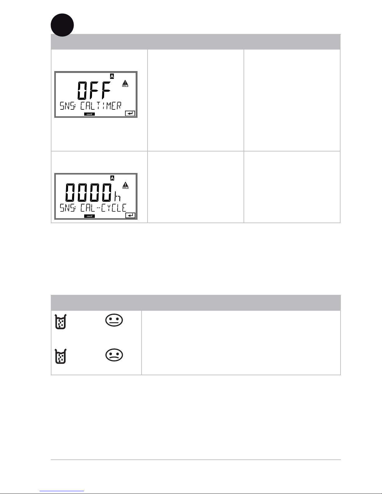
CAL TIMER OFF, FIX, ADAPT OFF
ON CAL-CYCLE 0...9999 h 0168 h
DS
(InduCon)
CIP COUNT ON/OFF OFF
ON CIP CYCLES 0...9999 CYC 0025 CYC
SIP COUNT ON/OFF OFF
ON SIP CYCLES 0...9999 CYC 0025 CYC

36
Con guration
Con guration Choices Default
Output 1 (OUT1)
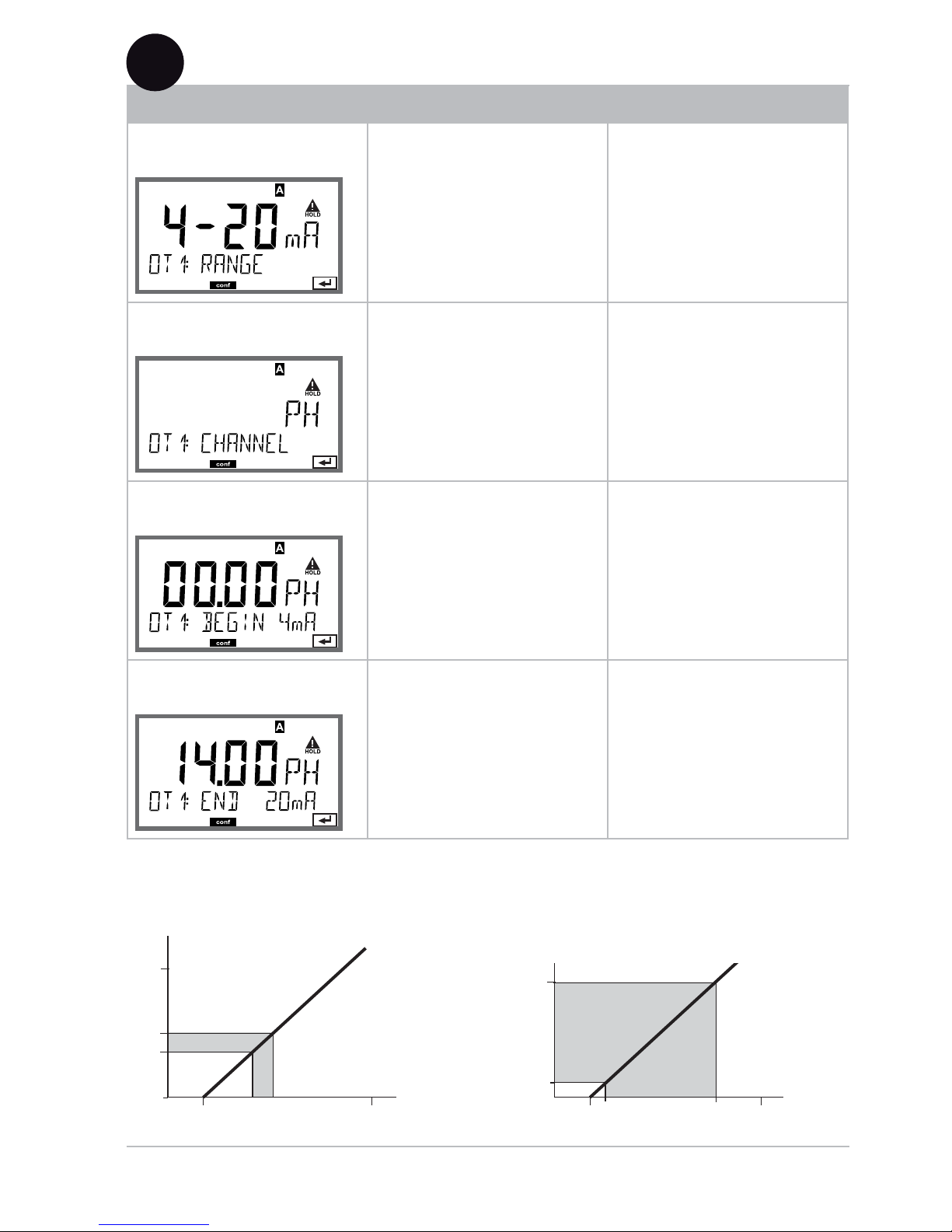
OT1: RANGE 0–20 mA, 4–20 mA 4-20 mA
CHANNEL PH/ORP/TMP PH
PH BEGIN 4mA (0 mA) –2.00...16 PH 00.00 PH
END 20 mA –2.00...16 PH 14.00 PH
ORP BEGIN 4mA (0 mA) –1999...1999 mV
END 20 mA –1999...1999 mV
TMP
°C
BEGIN 4mA (0 mA) –20...300 °C Select °C/°F
END 20 mA –20...300 °C for “Sensor“
TMP
°F
BEGIN 4mA (0 mA) –4...572 °F
END 20 mA –4...572 °F
FILTERTIME 0...120 SEC 0000 SEC
22mA-FAIL ON/OFF OFF
HOLD MODE LAST/FIX LAST
FIX HOLD-FIX (0) 4...22 mA 021.0 mA
Output 2 (OUT2)
OT2: RANGE 0–20 mA, 4–20 mA 4-20 mA
CHANNEL PH/ORP/TMP TMP
PH BEGIN 4mA (0 mA) –2.00...16 PH 00.00 PH
END 20 mA –2.00...16 PH 14.00 PH
ORP BEGIN 4mA (0 mA) –1999...1999 mV
END 20 mA –1999...1999 mV
TMP
°C
BEGIN 4mA (0 mA) –20...300 °C Select °C/°F
END 20 mA –20...300 °C for “Sensor“
TMP
°F
BEGIN 4mA (0 mA) –4...572 °F
END 20 mA –4...572 °F
FILTERTIME 0...120 SEC 0000 SEC
22mA-FAIL ON/OFF OFF
HOLD MODE LAST/FIX LAST
FIX HOLD-FIX (0) 4...22 mA 021.0 mA

37
Con guration
Con guration Choices Default
Temperature compensation (CORRECTION)
COR: TC LIQUID –19.99...19.99%/K 00.00%/K
TEMP EXT
*
ON/OFF OFF
ON I-INPUT 0...20 mA/4...20 mA 4...20 mA
°C BEGIN 4 mA –20...200 °C 000.0 °C
END 20 mA –20...200 °C 100.0 °C
°F BEGIN 4 mA –4...392 °F 032.0 °F
END 20 mA –4...392 °F 212.0 °F
Alarm (ALARM)
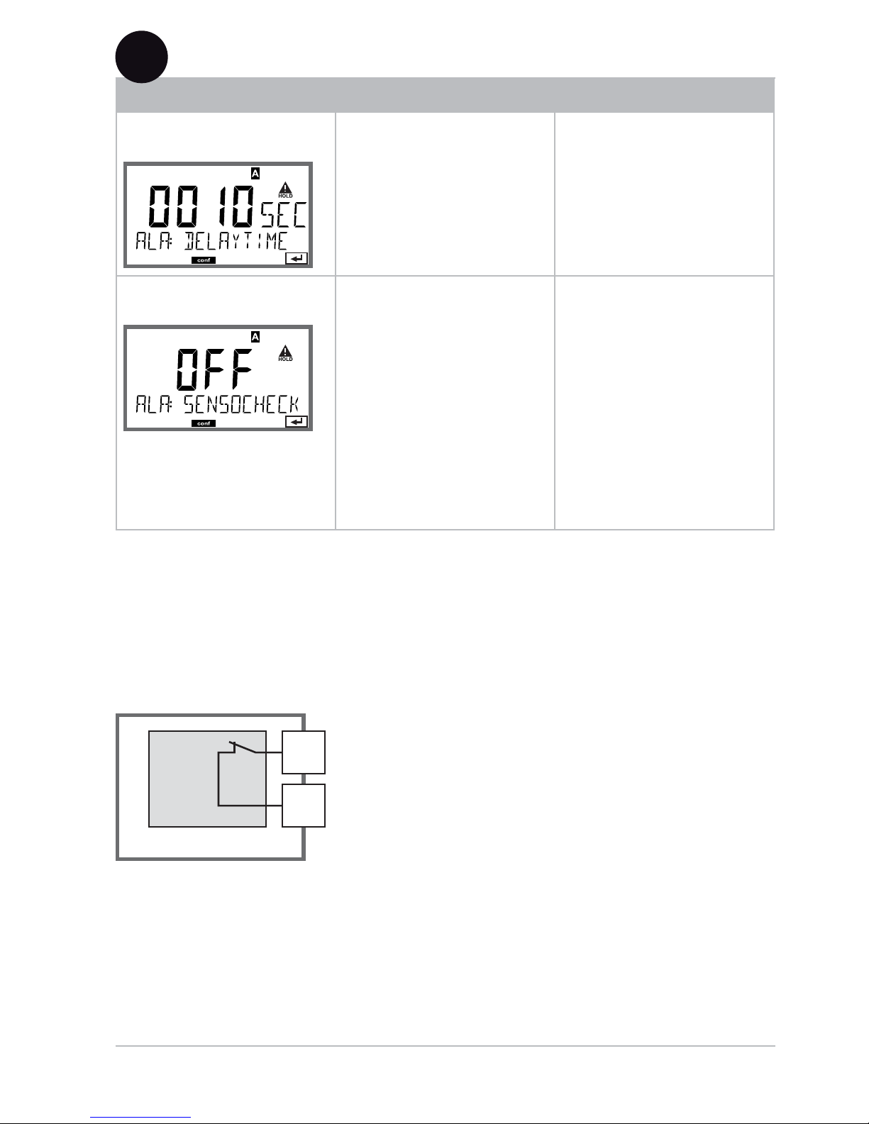
ALA: DELAYTIME 0...600 SEC 0010 SEC
SENSOCHECK ON/OFF OFF
Relay 1/2 (RL1/RL2)
REL: (Selected in text line) LIMITS, CONTROLLER LIMITS
RL1: CHANNEL PH/ORP/TMP PH
FUNCTION Lo LEVL, Hi LEVL Lo LEVL
CONTACT N/O, N/C N/O
LEVEL –2.00...16 PH
(-1999...1999 mV)
(-20...200 °C)
00.00 PH
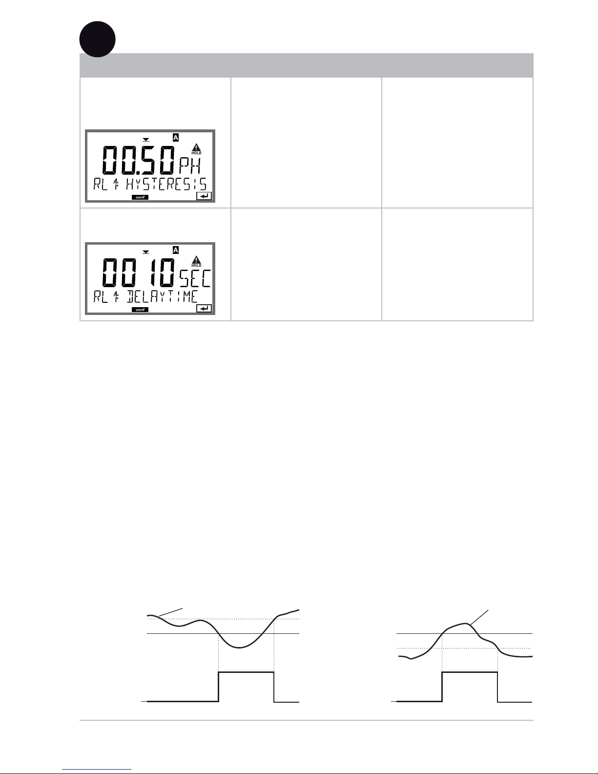
HYSTERESIS 0...10.00 PH 00.50 PH
DELAYTIME 0...9999 SEC 0010 SEC
RL2 CHANNEL PH/ORP/TMP PH
FUNCTION Lo LEVL, Hi LEVL Hi LEVL
CONTACT N/O, N/C N/O
LEVEL –2.00...16 PH
(-1999...1999 mV)
(-20...200 °C)
14.00 PH
HYSTERESIS 0...10.00 PH 00.50 PH
DELAYTIME 0...9999 SEC 0010 SEC
*) is only displayed if enabled and SENSOR TEMP EXT has been selected.

38
Con guration
Con guration Choices Default
REL: CTR CHANNEL PH/ORP/TMP PH
TYPE PLC / PFC PLC
PLC PULSE LEN 0...0600 SEC 0010 SEC
PFC PULSE FREQ 0...0180 P/M 0060 P/M
SETPOINT –2.00...16 PH
–1500...1500 mV
07.00 PH
DEAD BAND 0...10.00 PH 01.00 PH
P-GAIN 10...9999% 0100%
I-TIME 0...9999 SEC 0000 SEC
D-TIME 0...9999 SEC 0000 SEC
HOLD MODE Y LAST/Y OFF Y LAST
Cleaning contact (WASH)
WSH: (Select text line) WASH
PARSET A/B
WASH
WASH WASH CYCLE 0.0...999.9 h 000.0 h
WASH TIME 0...9999 SEC 0060 SEC
CONTACT N/O, N/C N/O
Parameter set (PARSET)
PAR: Select fixed parameter set
(A) or switch between A/B
via control input or manually in measuring mode
PARSET FIX /
CNTR INPUT /
MANUAL
PARSET FIX
(fixed parameter
set A)
Real-time clock (CLOCK)
CLK: FORMAT 24 h / 12 h
24 h TIME hh/mm 00..23:00...59 00:00
12 h TIME hh/mm 00...11 AM/
PM:00...59
00.00
DAY/MONTH 01...31/01...12 31.12.
YEAR 2000...2099 2006
Tag number (TAG)
TAG: (Input in text line) ___

39
Configuration (Original for Copy)
Two complete parameter sets are stored in the EEPROM.
As delivered, the two sets are identical but can be edited.
Please note:
Fill in your con guration data on the following pages or use them as
original for copy.
Parameter Parameter set A Parameter set B
SNS: Sensor type
---
*)
SNS: Temperature unit
---
SNS: Temp measurement
---
SNS: Manual meas. temp
---
SNS: Calibration temp
---
SNS: Manual cal temp
---
SNS: Calibration mode
---
SNS: Select buffer set
(-U1-, see Appendix)
---
SNS: Calibration timer
---
SNS: Calibration cycle
---
SNS: CIP counter
---
SNS: CIP cycles
---
SNS: SIP counter
---
SNS: SIP cycles
---
OT1: Current range
OT1: Process variable
OT1: Current start
OT1: Current end
*) These parameters cannot be adjusted in parameter set B,
the values are the same as in parameter set A.

40
(Original for Copy) Con guration
Parameter Parameter set A Parameter set B
OT1: Filter time
OT1: 22 mA error current
OT1: HOLD mode
OT1: HOLD-FIX current
OT2: Current range
OT2: Process variable
OT2: Current start
OT2: Current end
OT2: Filter time
OT2: 22 mA error current
OT2: HOLD mode
OT2: HOLD-FIX current
COR: Temp coefficient
COR: Ext. temp input
COR: Current range
COR: Current start
COR: Current end
ALA: Delay
ALA: Sensocheck on/off
REL: Usage
RL1: Process variable
RL1: Function
RL1: Contact response
RL1: Setpoint
RL1: Hysteresis
RL1: Delay
RL2: Process variable
RL2: Function
RL2: Contact response

41
Con guration (Original for Copy)
Parameter Parameter set A Parameter set B
RL2: Setpoint
RL2: Hysteresis
RL2: Delay
CTR: Process variable
CTR: Controller type
CTR: Pulse length
CTR: Pulse frequency
CTR: Setpoint
CTR: Neutral zone
CTR: P gain
CTR: I time
CTR: D time
CTR: HOLD mode
WSH: Usage
---
*)
WSH: Wash cycle
---
WSH: Wash duration
---
WSH: Contact response
---
PAR:
Parameter set
selection
---
CLK: Time format
---
CLK: Time hh/mm
---
CLK: Day/month
---
CLK: Year
---
TAG: Tag number
---
*) These parameters cannot be adjusted in parameter set B,
the values are the same as in parameter set A.
42
Con guration
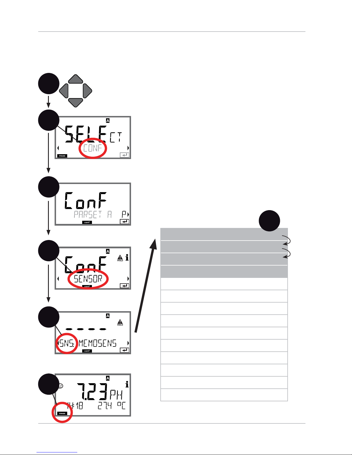
1
Sensor
Select: sensor type, temperature unit,
temp detection during measurement
Press any arrow key.1
Select 2 CONF using keys,
press enter.
Select parameter set using 3 keys,
press enter.
Select 4 SENSOR menu using keys,
press enter.
All items of this menu group are indicated by 5
the “SNS:” code.
Press enter to select menu,
edit with arrow keys (see next page).
Confirm (and proceed) with enter.
End: Press 6 meas key until the [meas] mode
indicator is displayed.
2
3
4
Select sensor type
Temperature unit
Temp detection during measurement
(Man. temperature)
Temp detection during calibration
(Man. temperature)
Calibration mode
(AUTO: Buffer set)
Calibration timer
Calibration cycle
Cleaning cycle counter
Cleaning cycles
Sterilization cycle counter
Sterilization cycles
5
enter
enter
6
enter
5
enter
meas

43
Con guration
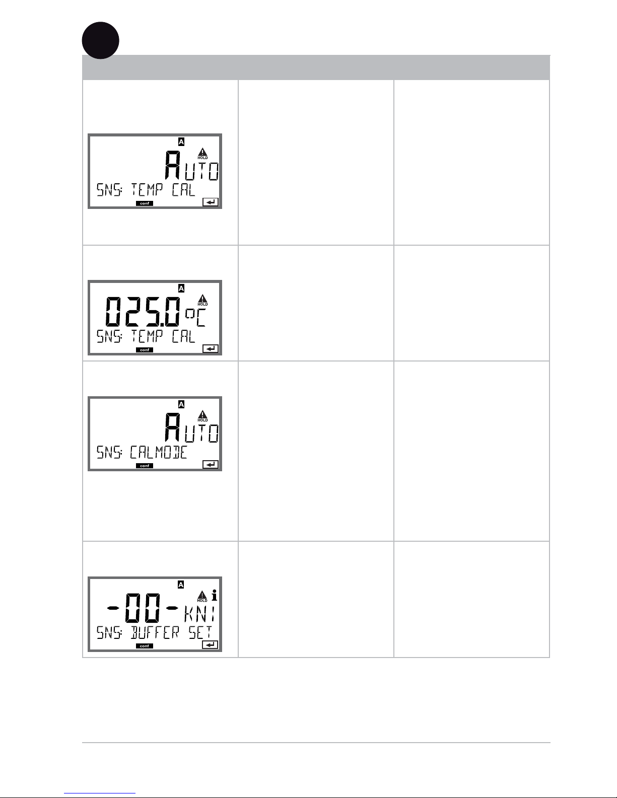
Menu item Action Choices
Select sensor type
Select sensor type using
keys.
Confirm with enter
STANDARD
ISFET
INDUCON (DS)
ISM-DISO (DS)
MEMOSENS (DS)
Temperature unit
Select °C or °F using
keys.
Confirm with enter
°C / °F
Temp detection
during measurement
Select mode using :
AUTO: Measured by
sensor
MAN: Direct input of
temperature, no measurement (see next step)
EXT: Temperature specified via current input
(only if TAN E enabled)
Confirm with enter
AUTO
MAN
EXT
(Manual temperature)
Modify digit using ,
select next digit using
keys.
Confirm with enter
–20...200 °C
(–4...+392 °F)
5

44
Con guration
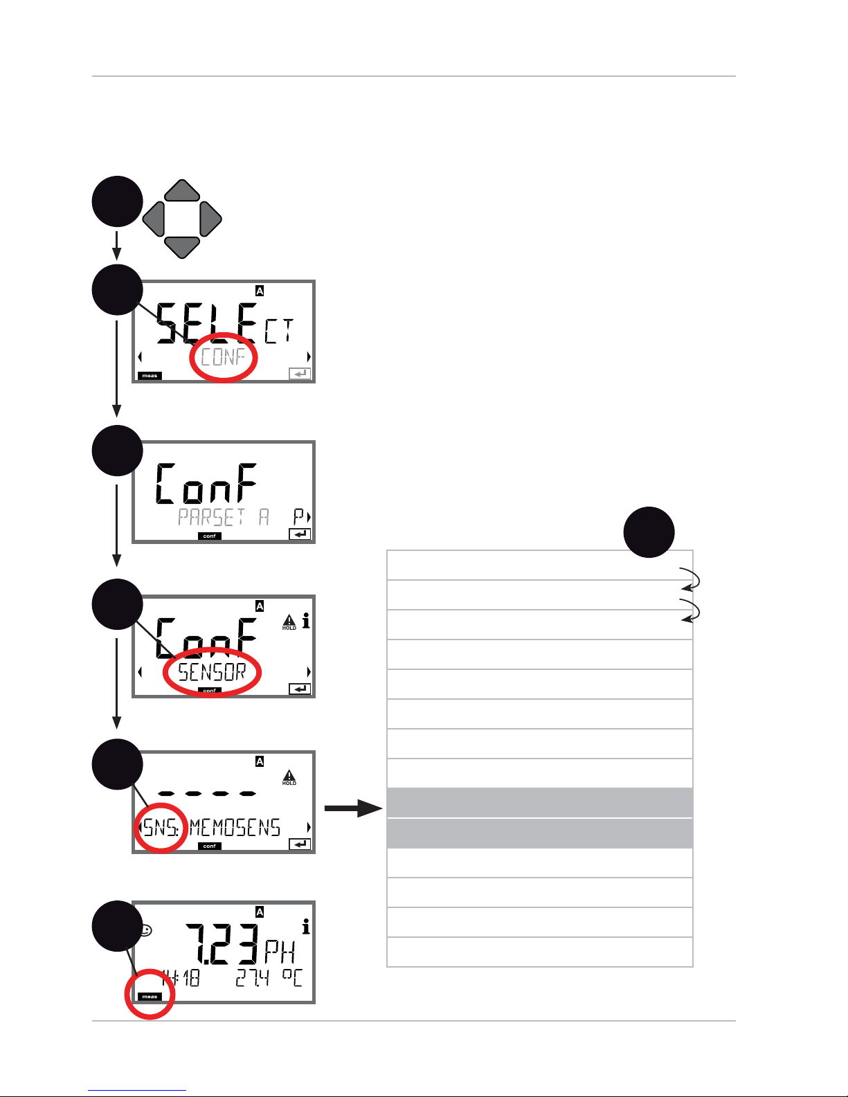
1
Sensor
Select: temp detection during calibration, calibration mode
Press any arrow key.1
Select 2 CONF using keys,
press enter.
Select parameter set using 3 keys,
press enter.
Select 4 SENSOR menu using keys,
press enter.
All items of this menu group are indicated by 5
the “SNS:” code.
Press enter to select menu,
edit with arrow keys (see next page).
Confirm (and proceed) with enter.
End: Press 6 meas key until the [meas] mode
indicator is displayed.
2
4
Select sensor type
Temperature unit
Temp detection during measurement
(Man. temperature)
Temp detection during calibration
(Man. temperature)
Calibration mode
(AUTO: Buffer set)
Calibration timer
Calibration cycle
Cleaning cycle counter
Cleaning cycles
Sterilization cycle counter
Sterilization cycles
5
enter
enter
6
enter
5
enter
meas
3
45
Con guration
Menu item Action Choices
Temp detection
during calibration
Select mode using :
AUTO: Measured by
sensor
MAN: Direct input of
temperature, no measurement (see next step)
EXT: Temperature
specified via current input
(only if TAN E enabled)
Confirm with enter
AUTO
MAN
EXT
(Manual temperature)
Modify digit using ,
select next digit using
keys.
Confirm with enter
–20...200 °C
(–4...+392 °F)
Calibration Mode
Select CALMODE using
keys:
AUTO: Calibration with
Calimatic buffer set
recognition
MAN: Manual input of
buffer solutions.
DAT: Input of adjustment
data of premeasured
sensors
Confirm with enter
AUTO
MAN
DAT
(AUTO: Bu er set)
Select buffer set using
keys (see buf-
fer tables for nominal
values).
Confirm with enter
-00-...-09-, -U1-
Pressing the info key displays the manufacturer
and nominal values in the
lower line.
5
46
Con guration
1
Sensor
Adjust: calibration timer, calibration cycle
Press any arrow key.1
Select 2 CONF using keys,
press enter.
Select parameter set using 3 keys,
press enter.
Select 4 SENSOR menu using keys,
press enter.
All items of this menu group are indicated by 5
the “SNS:” code.
Press enter to select menu,
edit with arrow keys (see next page).
Confirm (and proceed) with enter.
End: Press 6 meas key until the [meas] mode
indicator is displayed.
2
4
Select sensor type
Temperature unit
Temp detection during measurement
(Man. temperature)
Temp detection during calibration
(Man. temperature)
Calibration mode
(AUTO: Buffer set)
Calibration timer
Calibration cycle
Cleaning cycle counter
Cleaning cycles
Sterilization cycle counter
Sterilization cycles
5
enter
enter
6
enter
5
enter
meas
3
47
Con guration
Menu item Action Choices
Calibration timer
Adjust CALTIMER using
keys:
OFF: No timer
ADAPT: Maximum cal
cycle (adjust in the next
step)
FIX: Fixed cal cycle (adjust
in the next step)
Confirm with enter
OFF/ADAPT/FIX
With ADAPT, the calibration cycle is automatically
reduced depending on
the sensor load (high
temperatures and pH values) and for digital sensors also depending on
the sensor wear
Calibration cycle
Only with FIX/ADAPT:
Modify digit using
keys,
select next digit using
keys.
Confirm with enter
0...9999 h
5
Note for the calibration timer:
When Sensocheck has been ac
tivated in the Con guration > Alarm
menu, the expiration of the calibration interval is indicated by
Sensoface:
Display Status
+
+
Over 80% of the calibration interval has
already past.
The calibration interval has been exceeded.
The calibration timer settings apply to both parameter sets A and B.
The time remaining until the next due calibration can be seen in the
diagnostics menu (see Diagnostics chapter).

48
Con guration
1
Sensor
Adjust: CIP cleaning cycles, SIP sterilization cycles
Press any arrow key.1
Select 2 CONF using keys,
press enter.
Select parameter set using 3 keys,
press enter.
Select 4 SENSOR menu using keys,
press enter.
All items of this menu group are indicated by 5
the “SNS:” code.
Press enter to select menu,
edit with arrow keys (see next page).
Confirm (and proceed) with enter.
End: Press 6 meas key until the [meas] mode
indicator is displayed.
2
4
Select sensor type
Temperature unit
Temp detection during measurement
(Man. temperature)
Temp detection during calibration
(Man. temperature)
Calibration mode
(AUTO: Buffer set)
Calibration timer
Calibration cycle
Cleaning cycle counter
Cleaning cycles
Sterilization cycle counter
Sterilization cycles
5
enter
enter
6
enter
5
enter
meas
3

49
Con guration
Menu item Action Choices
CIP / SIP
The following adjustments are possible for INDUCON digital sensors:
Cleaning cycle
counter
Select ON or OFF using
keys.
Activates/deactivates logging in extended logbook
and counters (if provided)
Confirm with enter
ON/OFF
Cleaning cycles
Only with CIP COUNT ON:
Enter value using
keys.
Confirm with enter
0...9999 CYC
(0025 CYC)
Not with Memosens
Sterilization cycle
counter
Select ON or OFF using
keys.
Activates/deactivates logging in extended logbook
and counters (if provided)
Confirm with enter
ON/OFF
Sterilization cycles
Only with SIP COUNT ON:
Enter value using
keys.
Confirm with enter
0...9999 CYC
(0025 CYC)
Not with Memosens
The cleaning and sterilization cycles are counted to measure the load
on the sensor.
Suitable for biochemical applications (process temp approx. 0...50 °C,
CIP temperature > 55 °C, SIP temperature > 115 °C).
5

50
Con guration
Current range
Process variable
Current start
Current end
Time averaging lter
Output current during error
message
Output current during HOLD
Output current for HOLD FIX
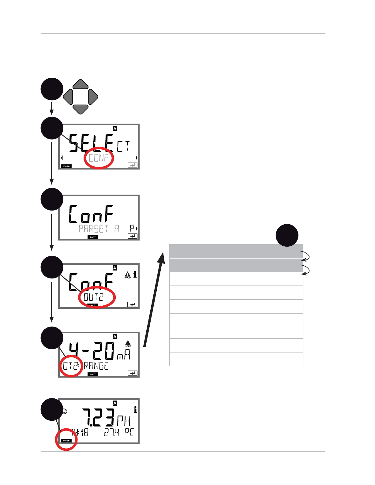
Current Output 1
Output current range, current start, current end
1
Press any arrow key.1
Select 2 CONF using keys,
press enter.
Select parameter set using 3 keys,
press enter.
Select 4 OUT1 menu using keys,
press enter.
All items of this menu group are indicated by 5
the “OT1:” code.
Press enter to select menu,
edit with arrow keys (see next page).
Confirm (and proceed) with enter.
End: Press 6 meas key until the [meas] mode
indicator is displayed.
2
4
5
enter
enter
6
enter
5
enter
meas
3
51
Con guration
Menu item Action Choices
Current range
Select 4-20 mA or
0-20 mA range using
keys.
Confirm with enter
4-20 mA / 0-20 mA
Process variable
Select using keys:
PH: pH value
ORP: Redox potential
TMP: Temperature
Confirm with enter
PH/ORP/TMP
Current start
Modify digit using ,
select next digit using
keys.
Confirm with enter
–2...16 pH (PH)
–1999...1999 mV (ORP)
–20...300 °C /
–4...572 °F (TMP)
Current end
Enter value using
keys.
Confirm with enter
–2...16 pH (PH)
–1999...1999 mV (ORP)
–20...300 °C /
–4...572 °F (TMP)
Assignment of measured values: Current start and current end
Output current
[pH]
20 4
14
0
20 4
7
5
[mA]
Example 1: Range pH 0...14
[mA]
Output current
7
5
5
Example 2: Range pH 5...7
Advantage: Higher resolution in
range of interest
[pH]

52
Con guration
Current Output 1
Adjust time interval of output lter
Current range
Process variable
Current start
Current end
Time averaging lter
Output current during error
message
Output current during HOLD
Output current for HOLD FIX
1
Press any arrow key.1
Select 2 CONF using keys,
press enter.
Select parameter set using 3 keys,
press enter.
Select 4 OUT1 menu using keys,
press enter.
All items of this menu group are indicated by 5
the “OT1:” code.
Press enter to select menu,
edit with arrow keys (see next page).
Confirm (and proceed) with enter.
End: Press 6 meas key until the [meas] mode
indicator is displayed.
2
4
5
enter
enter
6
enter
5
enter
meas
3

53
Con guration
Menu item Action Choices
Time averaging
lter
Enter value using
keys.
Confirm with enter
0...120 SEC
(0000 SEC)
Time Averaging Filter
To smoothen the current output, a low-pass lter with adjustable lter
time constant can be switched on. When there is a jump at the input
(100 %), the output level is at 63 % after the time interval has been
reached. The time interval can be set from 0 to 120 sec. If the time
interval is set to 0 sec, the current output directly follows the input.
Please note:
The lter only acts on the current output, not on the display,
the limit values, or the controller!
During HOLD the lter is not applied. This prevents a jump at the
output.
Time interval 0...120 s
5
pH
0/4-20 mA
Time interval 0...120 s
Temp
Display / Controller

54
Con guration
Current Output 1
Output current during Error and HOLD
Current range
Process variable
Current start
Current end
Time averaging lter
Output current during error
message
Output current during HOLD
Output current for HOLD FIX
1
Press any arrow key.1
Select 2 CONF using keys,
press enter.
Select parameter set using 3 keys,
press enter.
Select 4 OUT1 menu using keys,
press enter.
All items of this menu group are indicated by 5
the “OT1:” code.
Press enter to select menu,
edit with arrow keys (see next page).
Confirm (and proceed) with enter.
End: Press 6 meas key until the [meas] mode
indicator is displayed.
2
4
5
enter
enter
6
enter
5
enter
meas
3

55
Con guration
Menu item Action Choices
Output current
during error message
Select ON or OFF using
keys.
Confirm with enter
ON/OFF
Output current
during HOLD
LAST: During HOLD the
last measured value is
maintained at the output.
FIX: During HOLD a value
(to be entered) is maintained at the output.
Select using
Confirm with enter
LAST/FIX
Output current for
HOLD FIX
Only with FIX selected:
Enter current which is to
flow at the output during
HOLD
Enter value using
keys.
Confirm with enter
00.00...22.00 mA
(21.00 mA)
HOLD active
21
4
HOLD active
Output current
[mA]
Output signal HOLD
Setting FIX = 21.0 mA
Output signal for HOLD
LAST setting
Output Signal During HOLD:
5
56
Con guration
Current Output 2
Output current range, current start, current end
Current range
Process variable
Current start
Current end
Time averaging lter
Output current during error
message
Output current during HOLD
Output current for HOLD FIX
1
Press any arrow key.1
Select 2 CONF using keys,
press enter.
Select parameter set using 3 keys,
press enter.
Select 4 OUT2 menu using keys,
press enter.
All items of this menu group are indicated by 5
the “OT2:” code.
Press enter to select menu,
edit with arrow keys (see next page).
Confirm (and proceed) with enter.
End: Press 6 meas key until the [meas] mode
indicator is displayed.
2
4
5
enter
enter
6
enter
5
enter
meas
3

57
Con guration
Menu item Action Choices
Current range
Select 4-20 mA or
0-20 mA range using
keys.
Confirm with enter
4-20 mA / 0-20 mA
Process variable
Select using keys:
PH: pH value
ORP: Redox potential
TMP: Temperature
Confirm with enter
PH/ORP/TMP
.
.
.
All the following adjustments are made as for current output 1
(see there)!
5

58
Con guration
1
Press any arrow key.1
Select 2 CONF using keys,
press enter.
Select parameter set using 3 keys,
press enter.
Select 4 CORRECTION menu using keys,
press enter.
All items of this menu group are indicated by 5
the “COR:” code.
Press enter to select menu,
edit with arrow keys (see next page).
Confirm (and proceed) with enter.
End: Press 6 meas key until the [meas] mode
indicator is displayed.
2
4
enter
enter
6
enter
5
enter
meas
Temperature compensation,
process medium
Current input for
ext. temperature measurement
Current range
Current start
Current end
5
3
Temperature Compensation
TC process medium, current input for temp measurement

59
Con guration
Menu item Action Choices
Temp compensation,
process medium
For pH measurement
only: Enter temperature
compensation of the
process medium.
Enter value using
keys.
Confirm with enter
–19.99...+19.99 %/K
Current input for
ext. temperature
measurement
Only if enabled via TAN
and selected during
configuration (SENSOR).
Select ON or OFF using
keys.
Confirm with enter
ON/OFF
Current range
Select desired range
using keys.
Confirm with enter
4-20 mA / 0-20 mA
Current start
Modify digit using ,
select next digit using
keys.
Confirm with enter
Input range:
–20...200 °C /
–4...392 °F
Current end
Enter value using
keys.
Confirm with enter
Input range:
–20...200 °C/
–4...392 °F
5
60
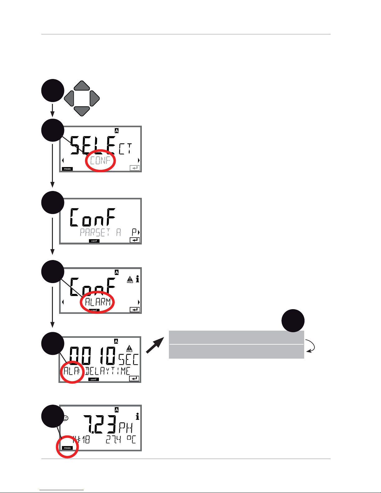
Con guration
Alarm
Alarm delay, Sensocheck
1
Press any arrow key.1
Select 2 CONF using keys,
press enter.
Select parameter set using 3 keys,
press enter.
Select 4 ALARM menu using keys,
press enter.
All items of this menu group are indicated by 5
the “ALA:” code.
Press enter to select menu,
edit with arrow keys (see next page).
Confirm (and proceed) with enter.
End: Press 6 meas key until the [meas] mode
indicator is displayed.
2
4
enter
enter
6
enter
5
enter
meas
Delay
Sensocheck
5
3
61
Alarm Contact
The alarm contact is closed during normal operation
(N/C). It opens in the case of alarm or power outage.
As a result, a failure message is provided even in the
case of wer failure or line breakage (fail-safe behavior).
For contact ratings, see Specifications.
17
18
Alarm
R3
Error messages can also be signaled by a 22 mA output current (see Error messages
and Configuration Output 1/Output 2).
Operating behavior of the alarm contact: see Operating States table.
The alarm delay time delays the color change of the display backlighting to red,
the 22 mA signal (if configured), and the alarm contact switching.
Con guration
Menu item Action Choices
Alarm delay
Enter value using
keys.
Confirm with enter
0...600 SEC
(010 SEC)
Sensocheck
Select Sensocheck
(continuous monitoring
of glass and reference
electrode)
Select ON or OFF using
keys.
Confirm with enter.
(At the same time,
Sensoface is activated.
With OFF, Sensoface is
also switched off.)
ON/OFF
5

62
Con guration
Limit Function
Relay 1
1
Press any arrow key.1
Select 2 CONF using keys,
press enter.
Select parameter set using 3 keys,
press enter.
Select 4 REL1/REL2 menu using keys,
press enter.
All items of this menu group are indicated by 5
the “RL1:” code.
Press enter to select menu,
edit with arrow keys (see next page).
Confirm (and proceed) with enter.
End: Press 6 meas key until the [meas] mode
indicator is displayed.
2
4
enter
6
enter
5
meas
Use of relays
Select process variable
Limit 1 switching characteristics
(function)
Limit 1 contact type
Limit 1 setpoint
Limit 1 hysteresis
Limit 1 delay
enter
5
3
enter

63
Con guration
Menu item Action Choices
Use of relays
Select in the text line
using keys:
Limit function (LIMITS)•
Controller •
(CONTROLLER)
Confirm with enter
LIMITS / CONTROLLER
Please note: Selecting
CONTROLLER leads to
Controller menu group
CTR.
Select process
variable
Select desired process
variable using keys.
Confirm with enter
PH/ORP/TMP
Limit 1 function
Select desired function
using arrow keys.
LoLevel: active if value
falls below / HiLevel:
active if value exceeds
setpoint
Confirm with enter
Lo LEVL / Hi LEVL
Limit 1
contact response
N/O: normally open
contact
N/C: normally closed
contact
Select using keys.
Confirm with enter
N/O / N/C
Limit 1 setpoint
Enter setpoint using
keys.
Confirm with enter
–2.00...16.00 PH
(00.00 PH) /
-1999...1999 mV /
–20...200 °C
5

64
Con guration
1
Press any arrow key.1
Select 2 CONF using keys,
press enter.
Select parameter set using 3 keys,
press enter.
Select 4 REL1/REL2 menu using keys,
press enter.
All items of this menu group are indicated by 5
the “RL1:” code.
Press enter to select menu,
edit with arrow keys (see next page).
Confirm (and proceed) with enter.
End: Press 6 meas key until the [meas] mode
indicator is displayed.
2
4
enter
6
enter
5
meas
Use of relays
Select process variable
Limit 1 switching characteristics
(function)
Limit 1 contact type
Limit 1 setpoint
Limit 1 hysteresis
Limit 1 delay
enter
5
Limit Function
Relay 1
3
enter
65
Con guration
Menu item Action Choices
Limit 1
hysteresis
Select hysteresis using
keys.
Confirm with enter
0...10.00 PH
(00.50 PH)
Limit 1 delay
The contact is activated
with delay (deactivated
without delay)
Adjust delay using
keys.
Confirm with enter
0...9999 SEC
(0010 SEC)
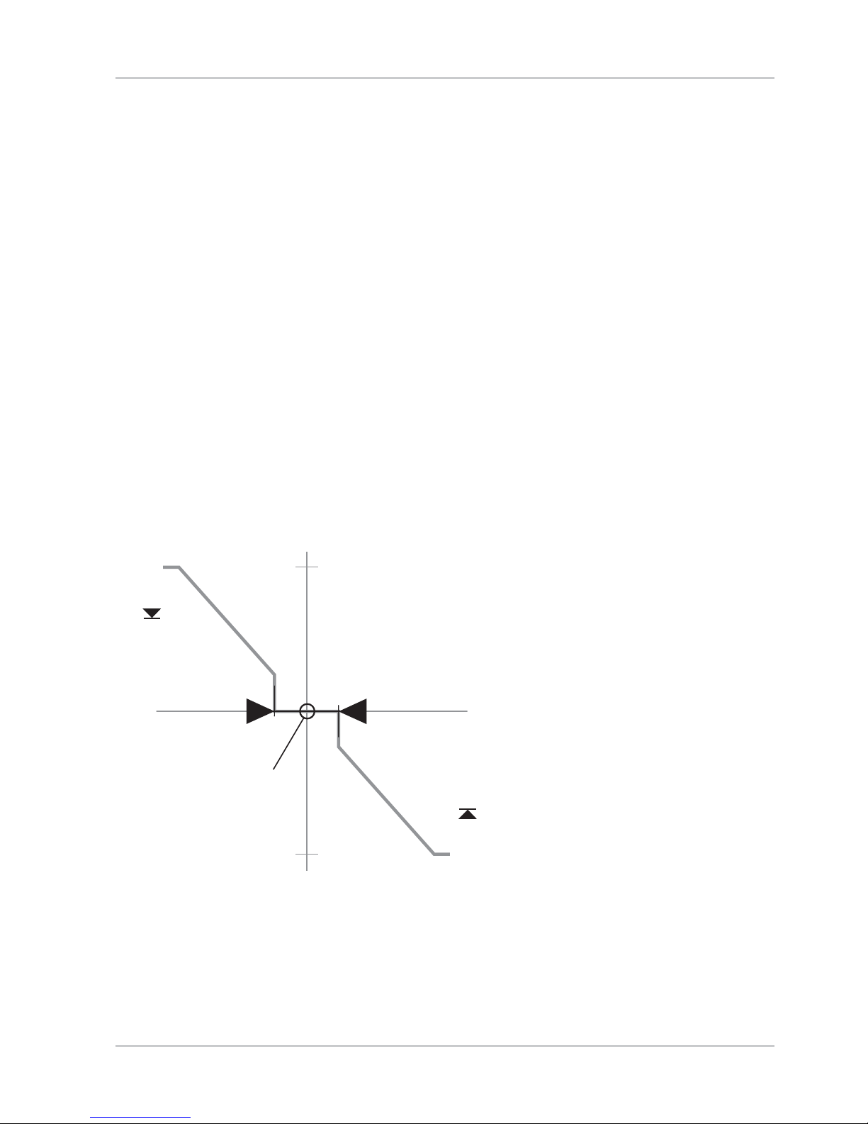
Limit Lo
Hysteresis +
Setpoint
Contact
0
1
Signal
Limit Hi
Hysteresis -
Signal
Setpoint
Contact
0
1
5
Application of Hysteresis:

66
Limit Function
Relay 2
Con guration
1
Press any arrow key.1
Select 2 CONF using keys,
press enter.
Select parameter set using 3 keys,
press enter.
Select 4 REL1/REL2 menu using keys,
press enter.
All items of this menu group are indicated by 5
the “RL2:” code.
Press enter to select menu,
edit with arrow keys (see next page).
Confirm (and proceed) with enter.
End: Press 6 meas key until the [meas] mode
indicator is displayed.
2
4
enter
6
enter
5
meas
Use of relays
Select process variable
Limit 2 switching characteristics
(function)
Limit 2 contact type
Limit 2 setpoint
Limit 2 hysteresis
Limit 2 delay
enter
5
enter
3

67
Con guration
Menu item Action Choices
Select process
variable
(CHANNEL)
Select desired process
variable using keys.
Confirm with enter
PH/ORP/TMP
Limit 2 function
(FUNCTION)
Select desired function
using arrow keys.
Confirm with enter
Lo LEVL / Hi LEVL
Limit 2 contact type
(CONTACT)
N/O: normally open
contact
N/C: normally closed
contact
Select using keys.
Confirm with enter
N/O / N/C
Limit 2 setpoint
(LEVEL)
Enter setpoint using
keys.
Confirm with enter
–2.00...16.00 PH
(14.00 PH) /
-1999...1999 mV /
–20...200 °C
Limit 2 hysteresis
(HYSTERESIS)
Select hysteresis using
keys.
Confirm with enter
0...10.00 PH
(00.50 PH)
Limit 2 delay
(DELAYTIME)
The contact is activated
with delay (deactivated
without delay)
Adjust delay using
keys.
Confirm with enter
0...9999 SEC
(0010 SEC)
Limit Lo
Hysteresis +
Setpoint
Contact
0
1
Signal
Limit Hi
Hysteresis -
Signal
Setpoint
Contact
0
1
5
Application of Hysteresis:

68
69
Controller Functions
Setpoint
Controller output
Yp [%]
+100 %
-100 %
Deviation Xw [pH]
Neutral zone Yp=0
Relay 1
Relay 2
Typical Applications
P Controller
Application for integrating control systems (e.g. closed tank, batch processes).
PI Controller
Application for non-integrating control systems (e.g. drains).
PID Controller
The additional derivative action compensates for measurement peaks.
Controller Characteristic

70
Controller Functions
Proportional action Y
P
Setpoint - Meas. value
Constant
Y
P
=
*
Controller output Y =
I action
with:
YP Proportional action
T
R
Reset time [s]
TD Rate time [s]
K
C
Controller gain [%]
Constant 5 (for pH)
500 mV (for ORP)
D action
dY
P
dt
1
T
R
P action
Controller Equations
YP +Y
P
dt + T
D
K
C
Neutral Zone
Tolerated deviation from desired value.
With the setting
“1 pH”, for example, a deviation of ± 0.5 pH from the
desired value is tolerated.
100 %
50 %
X
w
Process variables: pH/ (mV),
underneath: temp [K]
Controller
output Y
KC = 500 %
KC = 200 %
KC = 100 %
KC = 50 %
1 / (100) 2 / (200) 3 / (300) 4 / (400)
Proportional Action (Gradient KC [%])
Deviation
5 / (500)
[10] [20] [30] [40] [50]
71
Controller Functions
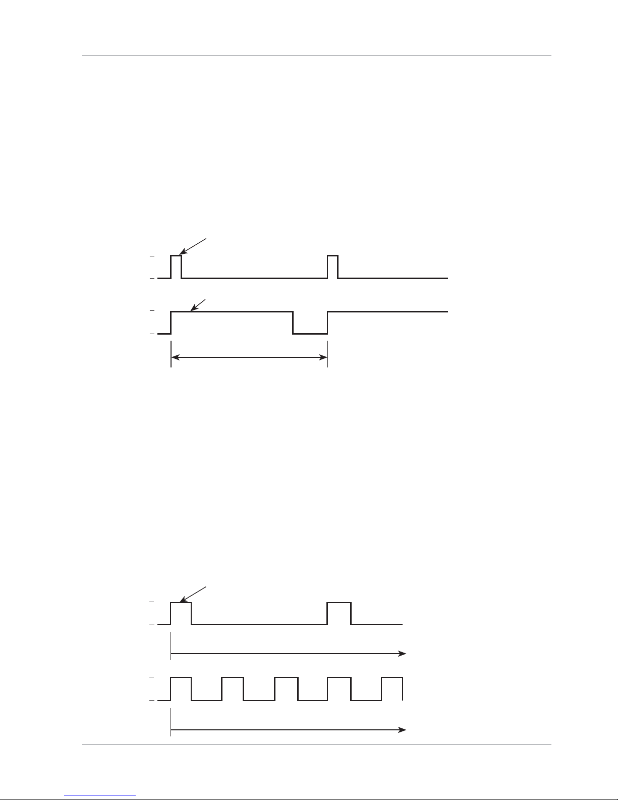
Pulse Length / Pulse Frequency Controller
Pulse Length Controller ( PLC)
The pulse length controller is used to operate a valve as an actuator.
It swit
ches the contact on for a time that depends on the controller
output. The period is constant. A minimum ON time of 0.5 sec is maintained even if the controller output takes corresponding values.
Output signal (relay contact) of pulse length controller:
ON time (Y = 80 %)
ON time (Y = 20 %)
Pulse length
1
0
1
0
Pulse Frequency Controller ( PFC)
The pulse frequency controller is used to operate a frequency c
ontrolled actuator (metering pump). It varies the frequency with
which the contacts are switched on. The maximum pulse frequency
[pulses/min] can be defined. It depends on the actuator.
The contact ON time is constant. It is automatically calculated from
the user-defined maximum pulse frequency:
Output signal (relay contact) of pulse frequency controller:
ON time
Pulse frequency (Y = 20%)
Pulse frequency (Y = 80%)
1
0
1
0
72
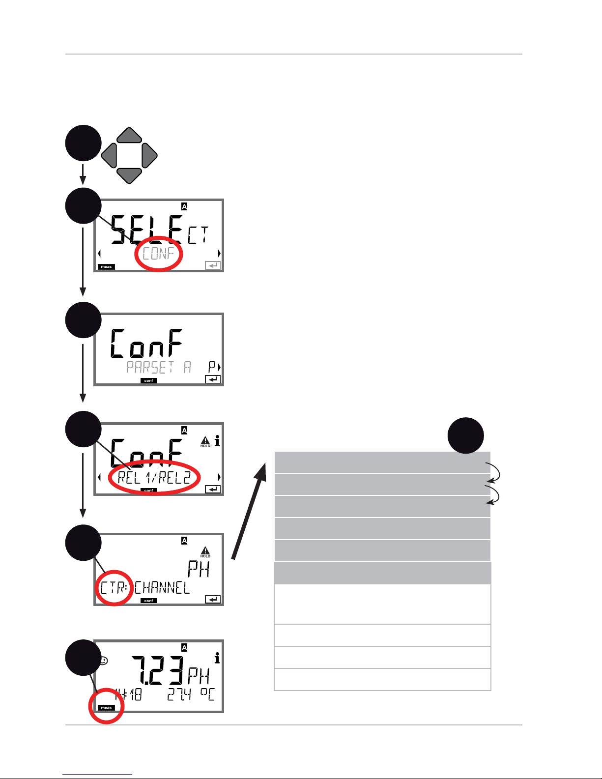
Con guration
Controller
(For description, see Controller Functions)
Process variable. Controller type. Setpoint.
1
Press any arrow key.1
Select 2 CONF using keys,
press enter.
Select parameter set using 3 keys,
press enter.
Select 4 REL1/REL2 menu using keys,
press enter.
All items of this menu group are indicated by 5
the “CTR:” code.
Press enter to select menu,
edit with arrow keys (see next page).
Confirm (and proceed) with enter.
End: Press 6 meas key until the [meas] mode
indicator is displayed.
2
4
enter
6
enter
5
meas
Use of relays
Select process variable
Controller type
Pulse length
Pulse frequency
Setpoint
Neutral zone
Controller: P action
Controller: I action
Controller: D action
Behavior during HOLD
enter
5
enter
3

73
Con guration
Menu item Action Choices
Select process
variable
Select desired process
variable using keys.
Confirm with enter
PH/ORP/TMP
Controller type
Pulse length controller
(PLC)
or pulse frequency
controller (PFC)
Select using keys.
Confirm with enter
PLC / PFC
Pulse length
Only with PLC:
Pulse length
Adjust using
keys.
Confirm with enter
0...0600 SEC
(0010 SEC)
Pulse frequency
Only with PFC:
Pulse frequency
Adjust using
keys.
Confirm with enter
0...0180 P/M
(0060 P/M)
(pulses per minute)
Setpoint
Adjust setpoint using
keys.
Confirm with enter
–2.00...16.00 PH
(07.00 PH) /
–1500...1500 mV
5

74
Controller
(For description, see Controller Functions)
Neutral zone. P, I, D actions. Behavior during HOLD
1
Press any arrow key.1
Select 2 CONF using keys,
press enter.
Select parameter set using 3 keys,
press enter.
Select 4 REL1/REL2 menu using keys,
press enter.
All items of this menu group are indicated by 5
the “CTR:” code.
Press enter to select menu,
edit with arrow keys (see next page).
Confirm (and proceed) with enter.
End: Press 6 meas key until the [meas] mode
indicator is displayed.
2
4
enter
6
enter
5
meas
Use of relays
Select process variable
Controller type
Pulse length
Pulse frequency
Setpoint
Neutral zone
Controller: P action
Controller: I action
Controller: D action
Behavior during HOLD
enter
5
Con guration
enter
3

75
Con guration
Menu item Action Choices
Neutral zone
Adjust neutral zone using
keys.
Confirm with enter
0...10.00 PH
(01.00 PH) /
0...2000 mV
Controller: P action
Adjust P action using
keys.
Confirm with enter
10...9999%
(0100%)
Controller: I action
Adjust I action using
keys.
Confirm with enter
0...9999 SEC
(0000 SEC)
Controller: D action
Adjust D action using
keys.
Confirm with enter
0...9999 SEC
(0000 SEC)
Behavior during
HOLD
Select response using
keys.
Confirm with enter
Y LAST / Y OFF
5
76
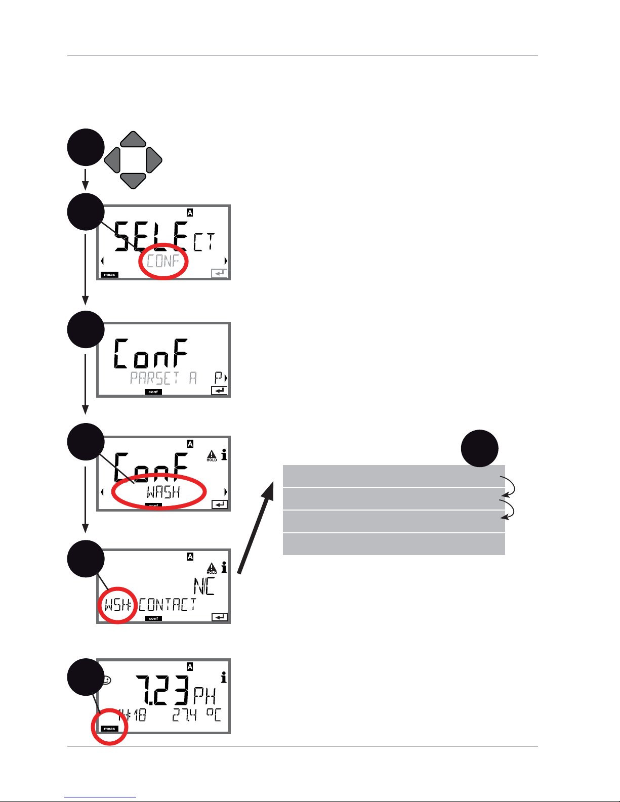
Con guration
WASH Contact
Control of rinsing probes or
signaling the parameter set
1
Press any arrow key.1
Select 2 CONF using keys,
press enter.
Select parameter set A using 3 keys,
press enter.
Select 4 WASH menu using keys, press
enter.
All items of this menu group are indicated by 5
the “WSH:” code.
Press enter to select menu,
edit with arrow keys (see next page).
Confirm (and proceed) with enter.
End: Press 6 meas key until the [meas] mode
indicator is displayed.
2
3
4
enter
6
enter
5
enter
meas
Function
Cleaning interval
Cleaning duration
Contact type
enter
5

77
Con guration
Menu item Action Choices
Function
Select WASH contact
function using keys.
Confirm with enter
WASH / PARSET A/B
WASH: Control of rinsing
probes
With PARSET A/B selected,
the contact signals:
“Parameter set A“
(open contact)
“Parameter set B“
(closed contact)
Cleaning interval
Only with WASH:
Adjust value using
keys.
Confirm with enter
0.0...999.9 h (000.0 h)
Cleaning duration
Only with WASH:
Adjust value using
keys.
Confirm with enter
0...9999 SEC (0060 SEC)
Contact type
Only with WASH:
N/O: normally open
contact
N/C: normally closed
contact
Select using keys.
Confirm with enter
N/O / N/C
5
Cycle interval
Cleaning Relax time (approx. 20 s)
HOLD

78
Con guration
Time and Date
Tag Number
1
Press any arrow key.1
Select 2 CONF using keys,
press enter.
Select parameter set A using 3 keys,
press enter.
4 Press enter
Select 5 CLOCK or TA G using keys, press
enter.
All items of this menu group are indicated by 6
the “CLK:” or “TAG” code.
Press enter to select menu,
edit with arrow keys (see next page).
Confirm (and proceed) with enter.
End: Press 7 meas key until the [meas] mode
indicator is displayed.
2
3
4
enter
6
enter
5
enter
meas
Time format
Time
Day and month
Year
Tag number
enter
5

79
Time and Date
Control of the calibration and cleaning cycles is based on the time and
date of the integrated real-time clock.
In measuring mode the time is shown in the lower display.
When using InduCon sensors, the calibration data is written in the
sensor head.
In addition, the logbook entries (cf Diagnostics) are provided with a
time stamp.
Please note:
After prolonged power outage (> 5 days) the time display is •
replaced by dashes and cannot be used for processing.
Enter the correct time.
There is no automatic switchover from winter to summer time!•
Be sure to manually adjust the time!
Con guration
Menu item Action Choices
Tag number
Select character using
keys,
select next digit using
keys.
Confirm with enter
A...Z, 0...9, – + < > ? / @
The first 10 characters are
seen in the display without scrolling.
Tag Number (“ TAG“)
You can enter a designation for the point of measurement (tag
number) in the lower display line. Up to 32 digits are possible.
Pressing meas (repeatedly) in the measuring mode indicates the tag
number.
Being part of the device con guration, the “TAG“ can be read out via
IrDA.
A standardized tag number helps, for example, to correctly re-install a
device after repair.
5
80
Digital Sensors
Operation
Stratos Pro can be operated with three di erent types of digital
sensors (Memosens, InduCon).
The following display examples refer to a transmitter and a digital
pH sensor (slight variations for other combinations).
The sensor type is selected during con guration.
The device only switches to measuring mode when the connected
sensor corresponds to the type con gured (Sensoface is happy):
Otherwise, an error message is released. The info icon is displayed.
You can display the error text in the bottom line using the keys.
Sensofac
e is sad (see table of error messages and Sensoface in the
Appendix):

81
Connecting a Digital Sensor
Step Action/Display Remark
Connect sensor
Before a digital sensor
is connected, the error
message “No sensor“ is
displayed.
Wait until the sensor
data are displayed.
The hourglass in the
display blinks.
Check sensor data
View sensor information using keys,
con rm
with enter.
The display color changes
to green.
Sensoface is happy.
Go to measuring
mode
Press meas, info, or
enter
After 60 sec the device
automatically returns to
measuring mode
(timeout).
Possible error messages
Sensor devaluated
Replace sensor
When this error message
appears, the sensor cannot be used any more.
Sensoface is sad.
Sensor defective
Replace sensor
When this error message
appears, the sensor
cannot be used.
Sensoface is sad.
Digital Sensors

82
Digital Sensors
Sensor Replacement
A digital sensor should only be replaced during HOLD mode to prevent unintended reactions of the outputs or contacts. When you rst
want to calibrate the new sensor, it can also be replaced in calibration
mode.
Step Action/Display Remark
Select HOLD mode Press any key to call
the selection menu,
select HOLD using
the keys, press
en
ter
to con rm.
Now the device is in
HOLD mode. The HOLD
mode can also be activated externally via the
HOLD input.
During HOLD the output
current is frozen at its
last value or set to a fixed
value.
Disconnect and
remove old sensor
Install and connect
new sensor.
Temporary messages
which are activated during the replacement are
indicated but not output
to the alarm contact and
not entered in the logbook.
Wait until the sensor
data are displayed.
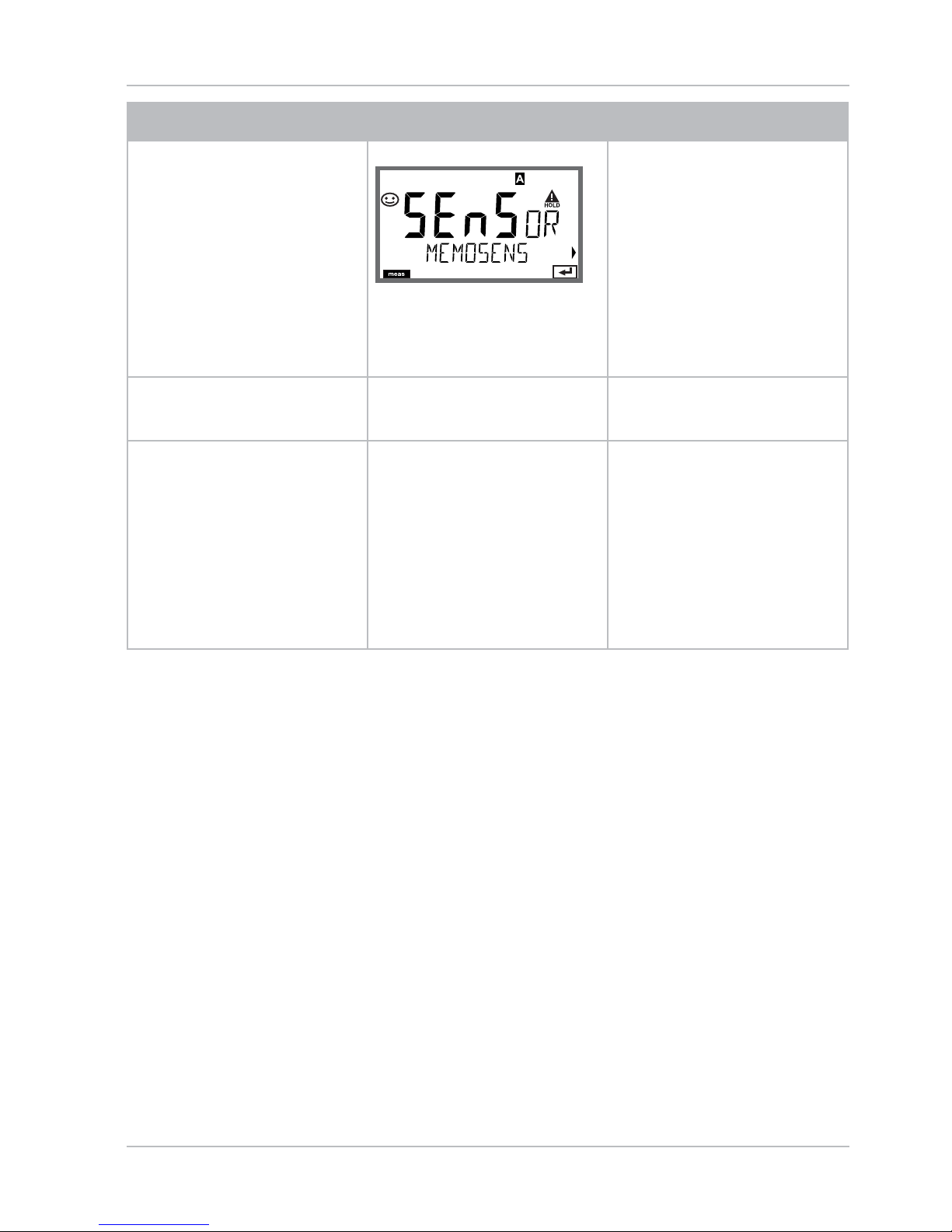
83
Digital Sensors
Step Action/Display Remark
Check sensor data
View sensor information using keys,
con rm
with enter.
You can view the sensor
manufacturer and type,
serial number, and last
calibration date.
Check measured
values
Exit HOLD Hit meas key:
Return to selection
menu.
Hold meas key
depressed:
Device switches to
measuring mode
The sensor replacement is
entered in the extended
logbook.

84
Calibration
Please note:
All calibration procedures must be performed by trained person-•
nel. Incorrectly set parameters may go unnoticed, but change the
measuring properties.
The response time of the sensor and temperature probe is •
considerably reduced when the sensor is rst moved about
in the bu er solution and then held still.
The device can only operate properly when the bu er solutions •
used correspond to the con gured set. Other bu er solutions, even
those with the same nominal values, may demonstrate a di erent
temperature response. This leads to measurement errors.
When using ISFET sensors or sensors with a zero point other
than pH 7, the nominal zero point must be adjusted each time a new
sensor is connected. This is important if you want to obtain reliable
Sensoface messages. The Sensoface messages issued during all further
calibrations are based on this basic calibration.

85
Calibration is used to adapt the device to the individual sensor
characteristics, namely asymmetry potential and slope.
Access to calibration can be protected with a passcode
(SERVICE menu).
First, you open the calibration menu and select the calibration mode:
CAL_PH Depending on con guation setting:
AUTO Automatic bu er recognition (Calimatic)
MAN Manual bu er input
DAT Input of premeasured electrode data
CAL_ORP ORP calibration
P_CAL Product calibration (calibration with sampling)
ISFET-ZERO Zero adjustment. Required for ISFET sensors, subse-
quently you can conduct either a one or a two-point
calibration.
CAL_RTD Temperature probe adjustment
Selecting a Calibration Mode
To preset CAL_PH (CONF menu / con guration):
Hold 1) meas key depressed (> 2 s) (measuring mode)
Press any arrow key: the selection menu appears2)
Select CONF mode using left / right arrow key3)
Select “SENSOR“ – “CALMODE“: AUTO, MAN, or DAT.4)
Press enter to con rm
Selection menu
Selected mode
(blinks)
1
2
3
4
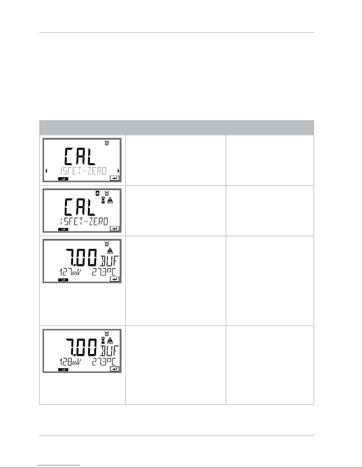
86
Zero Adjustment (ISFET)
This adjustment allows the use of ISFET sensors with di ering nominal
zero (pH only). The function is available when Sensor selection =
MEMOSENS has been set during con guration. Zero adjustment is
disabled for any other sensors.
The adjustment is made using a zero bu er (pH 7.00).
Permitted range for bu er value: pH 6.5 ... 7.5.
Temperature-corrected input. Maximum zero o set: ± 200 mV.
Display Action Remark
Select Calibration.
Press enter to proceed.
Ready for calibration.
Hourglass blinks.
Display (3 sec)
Now the device is in
HOLD mode.
Immerse sensor in a pH
7.00 bu er. Enter the
temperature-corrected
pH value in the range
6.50 to 7.50 using the
arrow keys (see bu er
table).
Con rm with enter.
If the zero o set of
the sensor is too
large (> ± 200 mV),
a CAL ERR error
message is generated. In that case the
electrode cannot be
calibrated.
Stability check.
The measured value
[mV] is displayed.
The “hourglass” icon is
blinking.
Please note:
Stability check can
be stopped (by
pressing enter).
However, this reduces calibration
accuracy.
Zero adjustment

87
Display Action Remark
At the end of the adjustment procedure
the zero o set [mV] of
the sensor is displayed
(based on 25 °C).
Sensoface is active.
Press enter to proceed.
This is not the nal
calibration value of
the sensor! Asymmetry potential
and slope must be
determined with a
complete 2-point
calibration.
Use the arrow keys to
select:
Repeat •
(repeat calibration) or
Measuring. •
Con rm with enter.
Place sensor in process.
End zero calibration
with enter.
After end of calibration, the outputs remain in HOLD mode
for a short time.
Note for Zero Adjustment
After having adjusted the zero o set, be sure to calibrate the sensor
following one of the procedures as described on the next pages.
Zero Adjustment (ISFET)

88
Adjustment (Calimatic)
Automatic Calibration ( Calimatic)
The AUTO calibration mode and the type of temperature detection
are selected during con guration. Make sure that the bu er solutions
used correspond to the con gured bu er set. Other bu er solutions,
even those with the same nominal values, may demonstrate a di erent temperature response. This leads to measurement errors.
Display Action Remark
Select Calibration.
Press enter to proceed.
Ready for calibration.
Hourglass blinks.
Select calibration
method: CAL_PH
Press enter to proceed.
Display (3 sec)
Now the device is in
HOLD mode.
Remove the sensor and
temperature probe,
clean them, and immerse them in the rst
bu er solution (in any
order). Start with enter
When manual input
of temperature has
been con gured, the
temp value in the
display blinks and
can be edited using
the arrow keys.
Bu er recognition.
While the “hourglass”
icon is blinking, the
sensor and temperature
probe remain in the rst
bu er solution.
The response time
of the sensor and
temperature probe
is considerably
reduced when the
sensor is rst moved
about in the bu er
solution and then
held still.
Bu er recognition
terminated, the nominal bu er value is
displayed.

89
Display Action Remark
At the end of the stability check, the value will
be saved and the asymmetry potential will be
displayed.
Calibration with the rst
bu er is terminated.
Remove the sensor and
temp probe from the
rst bu er solution and
rinse them thoroughly.
Use the arrow keys to
select:
END (1-point cal)•
CAL2 (2-point cal)•
REPEAT•
Press enter to proceed.
Please note:
Stability check can
be stopped after
10 sec (by pressing
enter). However, this
reduces calibration
accuracy. Display for
1-point cal:
Sensoface is active.
End with enter
2-point calibration:
Immerse sensor and
temperature probe in
the second bu er solution. Start with enter
The calibration process runs as for the
rst bu er.
Retract sensor and
temp probe out of
second bu er, rinse o ,
re-install.
Press enter to proceed.
The slope and asymmetry potential of
the sensor (based on
25 °C) are displayed.
Use the arrow keys to
select:
MEAS (end)•
REPEAT•
Press enter to proceed.
End: HOLD is deactivated with delay.
When 2-point cal is
ended:
Automatic Calibration (Calimatic)

90
Manual Calibration with Buffer Entry
The MAN calibration mode and the type of temperature detection
are selected during con guration. For calibration with manual bu er
speci cation, you must enter the pH value of the bu er solution used
in the device for the proper temperature. Any desired bu er solution
can be used for calibration.
Display Action Remark
Select Calibration.
Press enter to proceed.
Ready for calibration.
Hourglass blinks.
Display (3 sec)
Now the device is in
HOLD mode.
Remove the sensor and
temperature probe,
clean them, and immerse them in the rst
bu er solution.
Press enter to start.
When manual input
of temperature has
been con gured, the
temp value in the
display blinks and
can be edited using
the arrow keys.
Enter the pH value of
your bu er solution for
the proper temperature.
While the “hourglass”
icon is blinking, the
sensor and temperature
probe remain in the
bu er solution.
The response time
of the sensor and
temperature probe
is considerably
reduced when the
sensor is rst moved
about in the bu er
solution and then
held still.

91
Display Action Remark
At the end of the stability check, the value will
be saved and the asymmetry potential will be
displayed.
Calibration with the rst
bu er is terminated.
Remove the sensor and
temp probe from the
rst bu er solution and
rinse them thoroughly.
Use the arrow keys to
select:
END (1-point cal)•
CAL2 (2-point cal)•
REPEAT•
Press enter to proceed.
Please note:
Stability check can
be stopped after
10 sec (by pressing
enter). However, this
reduces calibration
accuracy. Display for
1-point cal:
Sensoface is active.
End with enter
2-point calibration:
Immerse sensor and
temperature probe
in the second bu er
solution.
Enter pH value.
Press enter to start.
The calibration process runs as for the
rst bu er.
Rinse sensor and temperature probe and
reinstall them.
Press enter to proceed.
Display of slope and
new asymmetry
potential (based on
25 °C).
Use the arrow keys to
select:
MEAS (end)•
REPEAT•
Press enter to proceed.
End: HOLD is deactivated with delay.
When 2-point cal is
ended:
Manual Calibration with Bu er Entry
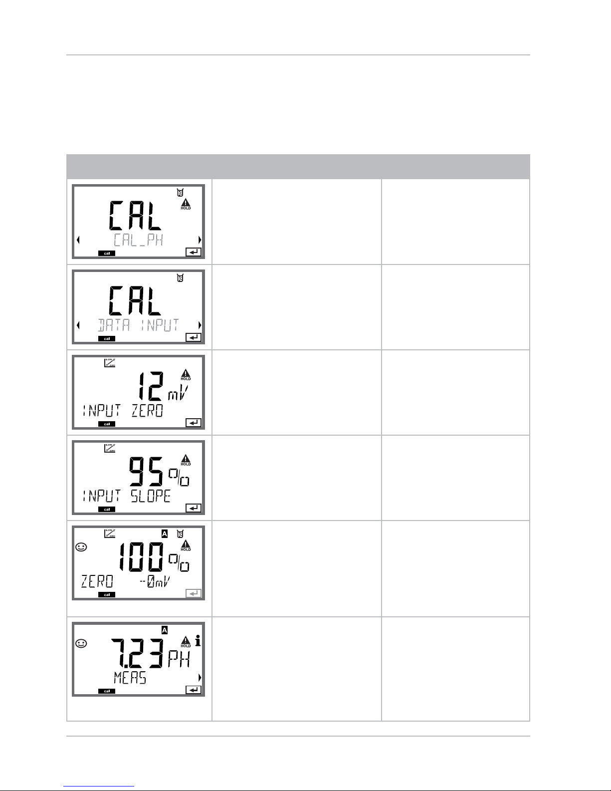
92
Data Entry of Premeasured Sensors
The DAT calibration mode must have been preset during
con guration.
You can directly enter the values for slope and asymmetry potential
of a sensor. The values must be known, e.g. determined beforehand in
the laboratory.
Display Action Remark
Select Calibration.
Press enter to proceed.
“Data Input“
Ready for calibration.
Hourglass blinks.
Display (3 sec)
Now the device is in
HOLD mode.
Enter asymmetry
potential [mV].
Press enter to proceed.
Enter slope [%].
The device displays
the new slope and
asymmetry potential
(at 25 °C).
Sensoface is active.
Use the arrow keys to
select:
MEAS (end)•
REPEAT•
Press enter to proceed.
End:
HOLD is deactivated
with delay.

93
Converting Slope to mV
Converting slope [%] to slope [mV/pH] at 25 °C
% mV/pH
78 46,2
80 47,4
82 48,5
84 49,7
86 50,9
88 52,1
90 53,3
92 54,5
94 55,6
96 56,8
98 58,0
100 59,2
102 60,4
Converting asymmetry potential to sensor zero point
= Sensor zero
= Asymmetry potential
= Slope
ZERO = 7 -
ZERO
V
AS
S
VAS[mV]
S [mV / pH]

94
Product calibration
Product Calibration (pH)
Calibration by sampling (one-point calibration).
During product calibration the sensor remains in the process.
The measurement process is only interrupted brie y.
Procedure:
The sample is measured in the lab or directly on the site using a por-1)
table meter. To ensure an exact calibration, the sample temperature
should correspond to the measured process temperature.
During sampling the device saves the currently measured value and
then returns to measuring mode. The “calibration“ mode indicator
blinks.
In the second step you enter the measured sample value in the 2)
device. From the di erence between the stored measured value and
entered sample value, the device calculates the new asymmetry
potential.
If the sample is invalid, you can take over the value stored during
sampling. In that case the old calibration values are stored.
Afterwards, you can start a new product calibration.
Display Action Remark
Select product
calibration: P_CAL.
Press enter to proceed.
Ready for calibration.
Hourglass blinks.
Display (3 sec)
Now the device is in
HOLD mode.
Take sample and save
value.
Press enter to proceed.
Now the sample can
be measured.

95
Display Action Remark
The device returns to
measuring mode.
From the blinking
CAL mode indicator
you see that product
calibration has not
been terminated.
Product calibration
step 2
Display (3 sec)
Now the device is in
HOLD mode.
The stored value is
displayed (blinking) and
can be overwritten with
the measured sample
value.
Press enter to proceed.
Display of new asymmetry potential (based
on 25°C).
Sensoface is active.
To end calibration:
Select MEAS, then
enter
To repeat calibration: Select REPEAT,
then enter
End of calibration After end of calibration, the outputs remain in
HOLD mode for a short time.
Product Calibration (pH)

96
ORP ( Redox) Calibration
The potential of a redox sensor is calibrated using a redox (ORP) bu er
solution. In the course of that, the di erence between the measured
potential and the potential of the calibration solution is determined
according to the following equation. During measurement this di erence is added to the measured potential.
= displayed ORP
= direct sensor potential
= delta value, determined during
calibration
mV
ORP
= mV
meas
+ ΔmV
mV
ORP
mV
meas
ΔmV
The sensor potential can also be related to another reference system
– e.g. the standard hydrogen electrode. In that case the temperaturecorrected potential (see table) of the reference electrode used must
be entered during calibration. During measurement, this value is then
added to the ORP measured.
Please make sure that measurement and calibration temperature are
the same since the temperature behavior of the reference electrode is
not automatically taken into account.
0
10
20
25
30
40
50
60
70
80
Temperature
[°C]
Ag/AgCl/KCl
1 mol/l
[∆mV]
Ag/AgCl/KCl
3 mol/l
[∆mV]
Thalamid
[∆mV]
Mercury
sulfate
[∆mV]
249
244
240
236
233
227
221
214
207
200
224
217
211
207
203
196
188
180
172
163
-559
-564
-569
-571
-574
-580
-585
-592
-598
-605
672
664
655
651
647
639
631
623
613
603
Temperature Dependence of Commonly Used
Reference Systems Measured Against SHE
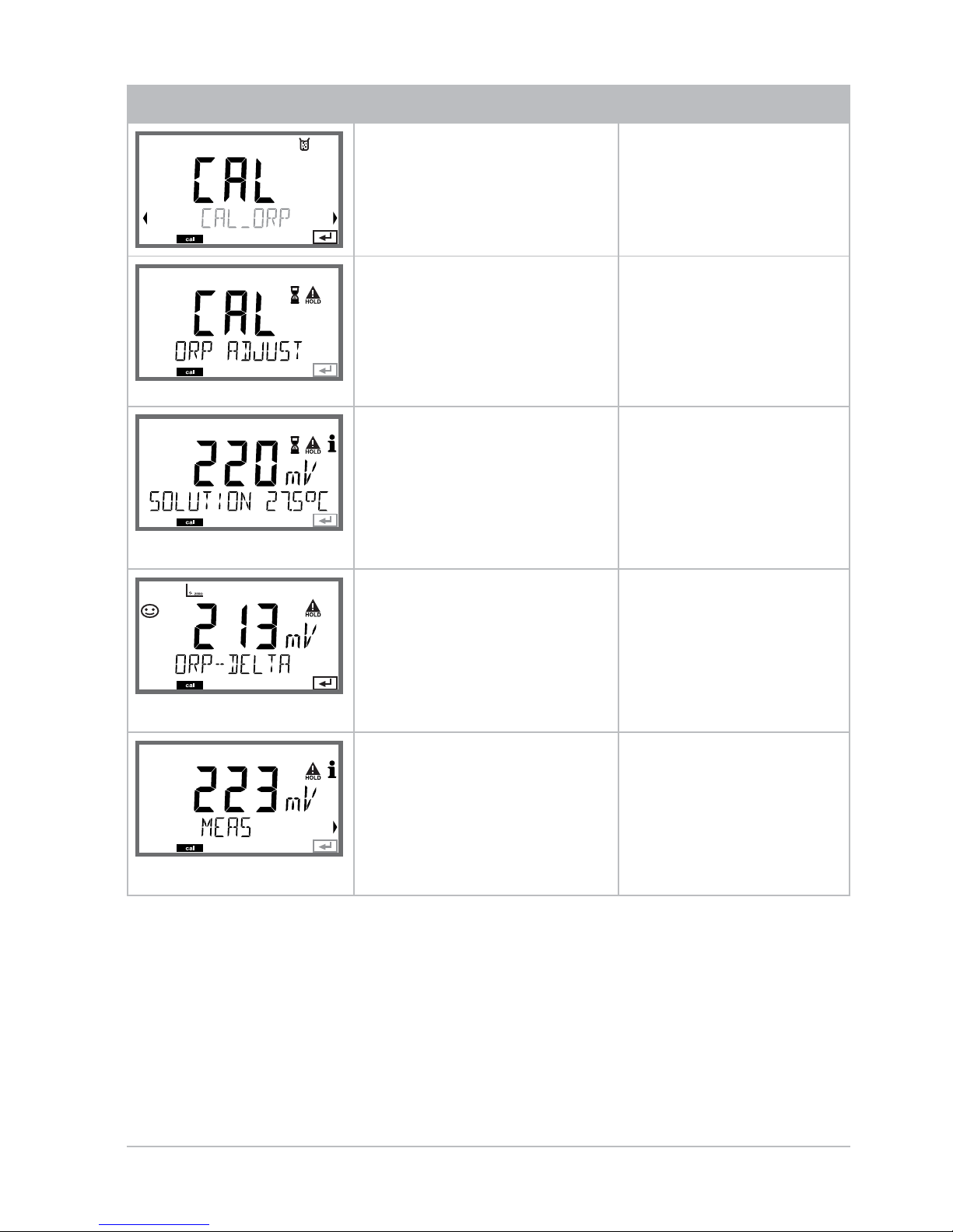
97
ORP Calibration
Display Action Remark
Select ORP calibration,
proceed with enter
Remove the sensor and
temperature probe,
clean them, and immerse them in the
redox bu er.
Display (3 sec)
Now the device is in
HOLD mode.
Enter setpoint value for
redox bu er.
Press enter to proceed.
The ORP delta value is
displayed (based on
25°C).
Sensoface is active.
Press enter to proceed.
To repeat calibration:
Select REPEAT. To end
calibration:
Select MEAS, then press
enter
After end of calibration, the outputs remain in HOLD mode
for a short time.
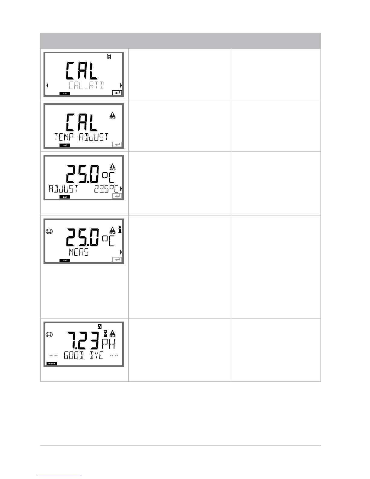
98
Temp Probe Adjustment
Display Action Remark
Select temp adjustment. Press enter to
proceed.
Wrong settings
change the measurement properties!
Measure the temperature of the process medium using an external
thermometer.
Display (3 sec)
Now the device is in
HOLD mode.
Enter the measured
temperature value.
Maximum di erence:
10 K.
Press enter to proceed.
Display of actual
temperature (uncompensated) in the
lower display.
The corrected temperature value is displayed.
Sensoface is active.
To end calibration:
Select MEAS, then
enter
To repeat calibration:
Select REPEAT, then
enter
After calibration is
ended, the device will
switch to measuring
mode.
After end of calibration, the outputs remain in HOLD mode
for a short time.
Temp probe adjustment
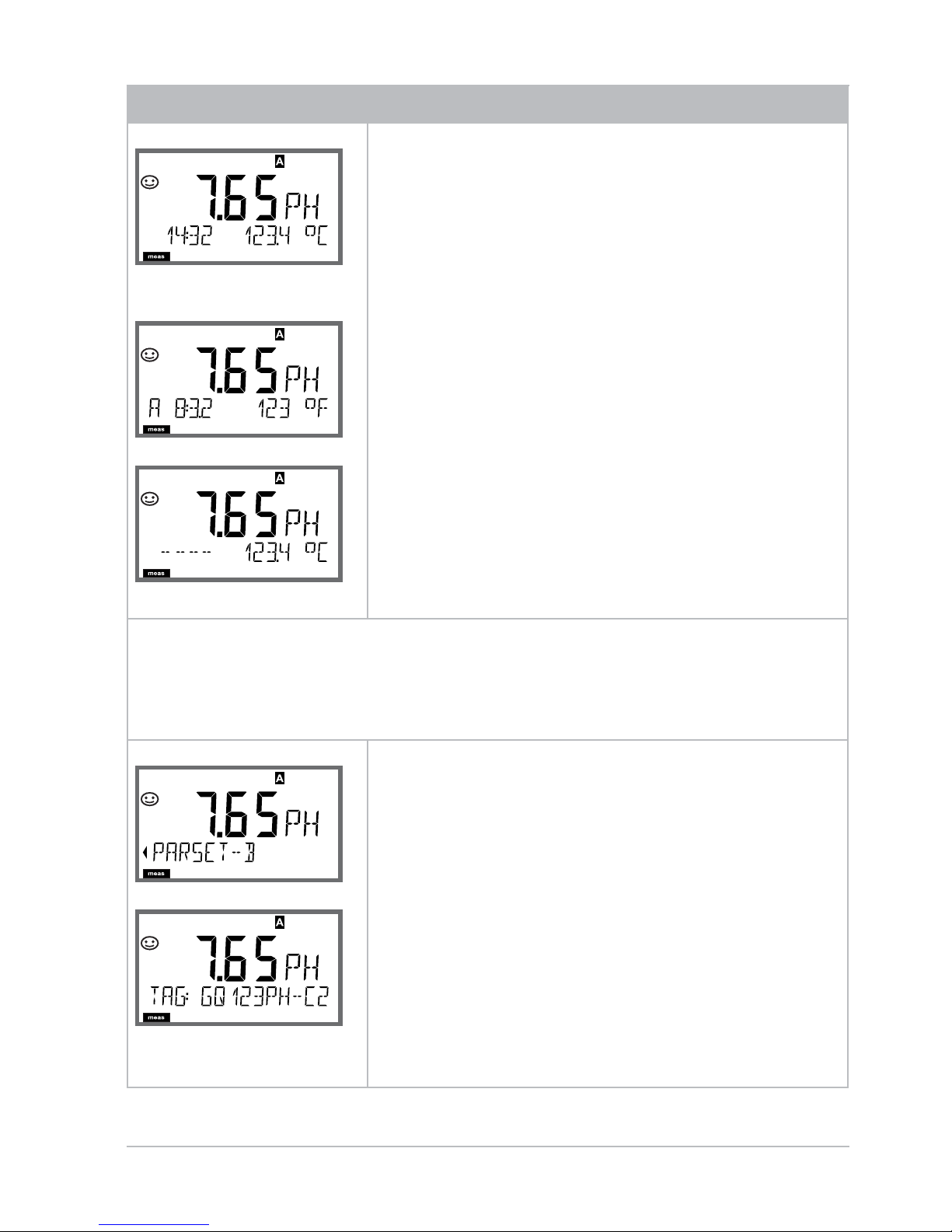
99
Measurement
Display Remark
or AM/PM and °F:
From the con guration or calibration menus,
you can switch the device to measuring
mode by pressing the meas key.
In the measuring mode the main display
shows the con gured process variable (pH,
ORP [mV], or temperature), the secondary display shows the time and the second
con gured process variable (pH, ORP [mV],
or temperature). The [meas] mode indicator
lights and the active parameter set (A/B) is
indicated.
Please note:
After prolonged power outage (> 5 days) •
the time display is replaced by dashes and
cannot be used for processing.
Enter the correct time.
Pressing the enter key brie y shows the output currents.
By pressing the meas key you can step through the following
displays. When no key has been pressed for 60 sec, the device
returns to the standard display.
Selecting the1) parameter set
(if set to “manual“ in the con guration).
Select the desired parameter set using
thearrow keys (PARSET A or PARSET B
blinks in the lo
wer display line).
Con rm with enter.
Further displays
(each with meas).
Display of tag number (“TAG“)2)
Display of 3) time and date

100
Measurement
Display Remark
With activated controller
you can also step through the following displays by pressing the
meas key. When no key has been pressed for 60 sec, the device
returns to the standard display.
Main display: Controller output Y
Secondary display: Setpoint
Depending on con guation setting:
pH, mV, or temperature.
 Loading...