


Stratos®Pro A4... MSPH/MSOXY
Instruction Manual
Latest Product Information:
www.knick.de

Warranty
Warranty
Defects occurring within 3 years from delivery date shall be remedied
free of charge at our plant (carriage and insurance paid by sender).
Sensors, ttings, and accessories: 1 year.
Subject to change without notice.
Return of Products Under Warranty
Please contact our Service Team before returning a defective device.
Ship the cleaned device to the address you have been given.
If the device has been in contact with process uids, it must be
decontaminated/disinfected before shipment. In that case, please
attach a corresponding certicate, for the health and safety of our
service personnel.
Disposal
Please observe the applicable local or national regulations concerning
the disposal of “waste electrical and electronic equipment”.
2

Documents Supplied
CD-ROM
Complete documentation:
• Instruction manuals
• Safety instructions
• Short instructions
Stratos® Pro Series
Safety Instructions
www.knick.de
Stratos® Pro A211 / A411
Short Instructions .........................3
Kurzübersicht .............................. 15
QuickStart .................................... 27
Быстрый старт ........................... 39
Inicio rápido ................................51
Início rápido ................................63
Guida rapida ................................ 75
Snabbstart.................................... 87
QuickStart .................................... 99
Other languages: www.knick.de
Safety Information
In ocial EU languages and others.
• ATEX / IECEX / FM / CSA
• EC Declarations of Conformity
Short Instructions
In German, English, French, Russian,
Spanish, Portuguese, Italian, Swedish
and Dutch.
More languages on CD-ROM and
on our website: www.knick.de
• Installation and commissioning
• Operation
• Menu structure
• Calibration
• Error messages and recommended actions
Specic Test Report
3

Contents
Documents Supplied .....................................................................3
Introduction
Intended Use
Safety Information
Overview of Stratos Pro A4... MSPH/MSOXY
Assembly
Package Contents
Mounting Plan, Dimensions
Pipe Mounting, Protective Hood
Panel Mounting
Installation
Installation Instructions
Rating Plates / Terminal Assignments
Power Supply, Signal Lines
Connecting Sensors A and B
Connecting a Memosens Sensor
User Interface, Keypad
Display
Signal Colors (Display Backlighting)
.................................................................................... 7
......................................................................................... 7
......................................................................... 8
........................................................................................10
..............................................................................10
..........................................................11
..................................................12
..................................................................................13
.....................................................................................14
...................................................................14
........................................14
............................................................. 15
.........................................................16
...............................................19
................................................................20
............................................................................................21
........................................... 21
............................. 9
Measuring Mode...........................................................................22
Selecting the Mode / Entering Values
Operating Modes
Menu Structure of Modes and Functions
HOLD Mode
Alarm
Overview of Configuration
Setup and Channel Selection on the Device
Channel Selection and Display Assignment
Configuration (Original for Copy)
OXY Sensor
...................................................................................................... 27
..........................................................................24
.........................................................................................26
.........................................................28
........................................................................................... 44
......................................23
.................................25
..........................29
............................29
................................................ 35
4

Contents
Measuring Mode ................................................................................ 50
Current Output 1
Current Output 2
Alarm Settings
Limit Function
Pulse Length / Pulse Frequency Controller
Controller
WASH Contact
Time and Date
Tag Number
PH Calibration ...............................................................................80
.............................................................................................72
................................................................................52
................................................................................58
.....................................................................................60
.....................................................................................62
..............................71
.....................................................................................76
..................................................................................... 78
.................................................................................................78
Pre-Calibrating Memosens Sensors
Selecting a Calibration Mode
Zero Adjustment (ISFET)
Automatic Calibration (Calimatic)
Manual Calibration with Buffer Entry
Data Entry of Premeasured Sensors............................................88
Product Calibration (pH)
OXY Calibration
Selecting a Calibration Mode
Zero Calibration
Product Calibration
Slope Calibration (Medium: Water)
Slope Calibration (Medium: Air)
Measurement
Diagnostics
Service
Operating States
Product Line and Accessories
..........................................................................................107
............................................................................93
.................................................................................. 94
..............................................................................100
..................................................................................102
.........................................................................111
.................................................................82
.................................................................90
........................................................................... 96
..................................................112
..........................................80
........................................................81
................................................84
.........................................86
........................................................94
............................................. 98
..................................................99
Specifications
..............................................................................113
5

Contents
Error Handling .............................................................................121
Error Messages
Sensoface
FDA 21 CFR Part 11
Electronic Signature – Passcodes
Audit Trail
Index
Passcodes
.............................................................................................129
Trademarks
............................................................................122
.....................................................................................125
....................................................................128
............................................................................................128
.........................................................................................139
.....................................................................................140
...............................................128
6

Introduction
Intended Use
Stratos Pro A4... MSPH/MSOXY is a two-channel process unit for measuring pH and dissolved oxygen and temperature using 2 Memosens
sensors
ceutical industry, as well as in the eld of industry, environment,
food processing and sewage treatment.
The sturdy molded enclosure can be xed into a control panel or
mounted on a wall or at a post. The protective hood, which is available as accessory, provides additional protection against direct
weather exposure and mechanical damage.
Plain-text messages in a large, backlit display allow intuitive operation. The colored display backlighting signals alarm messages (red) or
HOLD mode (orange).
The “Sensocheck“ automatic sensor monitoring and the “Sensoface“
function for clear indication of the sensor condition provide excellent
diagnostics.
The internal logbook (TAN SW-A002) can handle up to 100 entries –
up to 200 with AuditTrail (TAN SW-A003).
Password protection for granting access rights during operation can
be congured.
The oating, digital control input “HOLD“ allows remote controlled
switching to HOLD mode.
The “CONTROL“ input allows evaluation of external monitoring equipment, such as a ow monitoring system.
For that purpose, you can also monitor the current input (optional) for
keeping a desired value.
The internal PID process controller can be congured as pulse length
or pulse frequency controller.
The device provides two current outputs (for transmitting the two
values measured for pH and oxygen, for example) and four oating
relay contacts. A time-controlled cleaning function can be congured.
Current is provided through a universal power supply
24...230VAC/DC, AC: 45 ... 65 Hz.
. It is used for biotechnology applications, in the pharma-
7

Safety Information
Safety information
Be sure to read and observe the following instructions!
The device has been manufactured using state of the art technology
and it complies with applicable safety regulations.
When operating the device, certain conditions may nevertheless lead
to danger for the operator or damage to the device.
See also separate document:
• “Safety Instructions“
(EC Declaration of Conformity, Certicates)
CAUTION!
Commissioning must only be performed by trained personnel authorized by the operating company! Whenever it is likely that protection
has been impaired, the device shall be made inoperative and secured
against unintended operation.
The protection is likely to be impaired if, for example:
• the device shows visible damage
• the device fails to perform the intended measurements
• after prolonged storage at temperatures above 70 °C
• after severe transport stresses
Before recommissioning the device, a professional routine test must
be performed. This test must be carried out at the manufacturer's
factory.
Please note:
Before commissioning, you must prove that the device may be
connected with other equipment.
Terminals:
Screw terminal, suitable for single wires / exible leads up to 2.5 mm
(AWG 14).
Recommended torque for the terminal screws: 0.5 ... 0.6 Nm.
8
2

Overview of Stratos Pro A4... MSPH/MSOXY
Overview
Power supply
RS 485 A
RS 485 B
GND/Shield
Power supply
RS 485 A
RS 485 B
GND
Shield
1
2
3
4
A
B
C
D
E
Sensor A
(pH)
Sensor B
"MK-MS"
module
(OXY)
Output 1
Output 2
R1
R2
9
10
7
8
14
15
16
5
6
11
12
13
Current
HOLD
Control
input
input
input
Alarm
Wash
R3
Power
17
18
19
20
21
22
9

Assembly
Package Contents
Check the shipment for transport damage and completeness!
The package should contain:
• Front unit, rear unit, bag containing small parts
• Specific test report
• Documentation (cf Pg 3)
• CD-ROM
11
10
9
8
7 6 5
Fig.: Assembling the enclosure
1) Jumper (3 x)
2) Washer (1 x), for conduit
mounting: Place washer
between enclosure and nut
3) Cable tie (3 x)
4) Hinge pin (1 x), insertable
from either side
5) Enclosure screw (4 x)
1
2
3
4
6) Sealing insert (1 x)
7) Rubber reducer (1 x)
8) Cable gland (3 x)
9) Filler plug (3 x)
10) Hexagon nut (5 x)
11) Sealing plug (2 x), for sealing
in case of wall mounting
10

Mounting Plan, Dimensions
Assembly
74
148
14
6.2
34
42
148
42
80
42
117
21
1
43
2
1) Cable gland (3 x)
2) Knockouts for cable gland or
½" conduit,
21.5 mm dia. (2 knockouts)
3
Conduits not included!
3) Knockout for pipe mounting
4
(4
x)
4) Knockout for wall mounting
x)
(2
41
Fig.: Mounting plan (All dimensions in mm!)
11

Assembly
Pipe Mounting, Protective Hood
ø40...ø60
1) Hose clamp with worm gear
drive to DIN 3017 (2 x)
1
2
3
4
Fig.: ZU 0274 pipe-mount kit (All dimensions in mm!)
2) Pipe-mount plate (1 x)
3) For vertical or horizontal posts
or pipes
4) Self-tapping screw (4 x)
147199
185
91
Fig.: ZU 0737 protective hood for wall and pipe mounting
(All dimensions in mm!)
12

Panel Mounting
<30 76 31
Assembly
1) Circumferential sealing
(1 x)
2) Screw (4 x)
3) Position of control panel
4) Span piece (4 x)
5) Threaded sleeve (4 x)
Cutout
138 x 138 mm (DIN43700)
1
1...22
2345
Fig.: ZU 0738 panel-mount kit (All dimensions in mm!)
13

Installation
Installation Instructions
• Installation of the device must be carried out by trained experts in
accordance with this instruction manual and as per applicable local
and national codes.
• Be sure to observe the technical specications and input ratings
during installation!
• Be sure not to notch the conductor when stripping the insulation!
• The supplied current must be galvanically isolated. If not, connect
an isolator module.
• All parameters must be set by a system administrator prior to
commissioning!
Terminals:
suitable for single wires / exible leads up to 2.5 mm2 (AWG 14)
Rating Plates / Terminal Assignments
Fig.: Terminal assignments of Stratos Pro A4...
Fig.: Stratos Pro A4...N rating plate at outside bottom of front
14

Power Supply, Signal Lines
Connect the power supply for Stratos Pro A4.. MSPH/MSOXY
to terminals 21 and 22
(24...230 V AC, 45 ...65Hz/24...80 V DC)
Areas for placing the
screwdriver to pull out
the terminals
1 22
Assignments
Fig.: Terminals, device opened, back of front unit
15

Connecting Sensors A and B
Connect the sensor lines with the corresponding sensor terminals.
Sensor B (Oxy)
connections
Areas for placing the
screwdriver to pull out
the terminals
1 22
Sensor A (pH)
connections
Fig.:
Terminals, device opened, back of front unit
16

Memosens Cable CA/MS-...
Intended Use
Connecting cable for contactless inductive digital transmission of
measured signals (Memosens®).
The connecting cable consists of an inductive connector for digital
Memosens® sensors (bayonet lock). It allows connecting the ferruleterminated wires from the sensor loop of the transmitter. Contactless
inductive digital transmission of signals and energy eliminates the
inuence of humidity, electromagnetic elds and corrosion.
Specications
Material PEEK
Cable diameter 6.3 mm
Cable 2x2, twisted wire pairs
Length up to 100 m
Process temperature –20°C...135°C
Ingress protection IP 68
Model Code
Cable type Cable length Order number
Memosens® cable 3 m CA/MS-003NAA
5 m CA/MS-005NAA
10 m CA/MS-010NAA
20 m CA/MS-020NAA
Brown
Green
Yellow
White
Transparent
Power supply +
RS485 (A)
RS485 (B)
Power supply – (GND)
Shield
17

18

Connecting a Memosens Sensor
Example:
Measuring task: pH, temp and DO, temp
Sensors (example): SE532/1-NMSN, SE706 Memosens (both Knick)
Cable CA/MS-003-NAA
Terminal row 1
Channel A / pH
HE
RS 485 (A)
RS 485 (B)
1 2 3 4
Yellow
Brown
Green
White
GND/shield
Shield
(transparent)
Module terminal
Channel B / Oxy
HE
RS 485 (A)
RS 485 (B)
A B C D
Green
Yellow
Brown
GND
White
shield
E
Shield
(transparent)
Memosens
Memosens
Sensor(s) Cable Device
19

User Interface, Keypad
1
SENS
MEMO
2
3
1 IrDA transmitter/receiver
2 Display
3 Keypad
4 Rating plate
4
(enclosure bottom)
Key Function
meas • Return to last menu level
• Directly to measuring mode (press > 2 s)
info
enter
Arrow keys
up / down
Arrow keys
left / right
• Retrieve information
• Show error messages
• Measuring mode: Display output current
• Conguration: Conrm entries,
next conguration step
• Calibration:
Continue program ow
• Measuring mode: Call menu
• Menu: Increase/decrease a numeral
• Menu: Selection
• Measuring mode: Call menu
• Previous/next menu group
• Number entry: Move between digits
20

23
Display
1 2 3 4 5 6 7 8 9 10 11
MEMO
171819202122
SENS
12
13
14
24
15
16
1 Temperature
2 Sensocheck
3 Interval/response time
4 Sensor data
5 Sensor worn out
6 Limit values
7 Alarm
8 Service
9 Sensor A/B
10 Calibration
11 Memosens connected
12 Waiting time running
13 Info available
14 Hold mode active
15 Main display
16 Secondary display
17 Proceed using enter
18 Not used
19 Diagnostics
20 Conguration mode
21 Calibration mode
22 Measuring mode
23 Sensoface
24 Unit symbols
Signal Colors (Display Backlighting)
Red Alarm
Orange HOLD mode (Calibration, Conguration, Service)
Turquoise Diagnostics
Green Info
Purple Sensoface message
21

Measuring Mode
After the operating voltage has been connected, the analyzer
automatically goes to “Measuring“ mode.
To call the measuring mode from another operating mode
(e.g. Diagnostics, Service): Hold meas key depressed (> 2 s).
Sensoface indicator
(sensor status)
Time
Mode indicator
(measuring)
Hold meas key
depressed to call the
measuring mode
(pressing once more
switches the display)
In measuring mode the display indicates:
• Measured values as selected (OUT 1 / OUT 2) and time (24/12 h
AM/PM) or temperature in °C or °F (formats selected during
conguration)
By pressing the meas key in measuring mode you can view the
following displays (for approx. 60 sec):
• Measured values channel A and measured values channel B
• Measured value and tag (point of measurement designation –
entered during conguration)
• Time and date
• Controller (if congured), upper display: controller output Y,
lower display: setpoint (can be edited)
Pressing the enter key shows the output currents. They are displayed
as long as enter is held depressed, then the measured-value display
will return after 3 sec.
Process variable
(pH)
Process variable
(Oxy)
enter key
22
You must congure the device for the respective measurement
task!

Selecting the Mode / Entering Values
To select the operating mode:
1) Hold meas key depressed (> 2 s) (measuring mode)
2) Press any arrow key: the selection menu appears
3) Select operating mode using left / right arrow key
4) Press enter to conrm the selected mode
Selection menu
Selected mode
(blinks)
1
To enter a value:
5) Select numeral: left / right arrow key
6) Change numeral: up / down arrow key
7) Conrm entry by pressing enter
SENS
MEMO
5
2
3
4
6
7
23

Operating Modes
Diagnostics
Display of calibration data, display of sensor data, performing a device self-test,
viewing the logbook entries, display of hardware/software versions of the individual
components. The logbook can store 100 events (00...99). They can be displayed
directly on the device. The logbook can be extended to 200 entries using a TAN
(Option).
HOLD
Manual activation of HOLD mode, e.g. for replacing a digital sensor.
The signal outputs adopt a defined state.
Calibration
Every sensor has typical characteristic values, which change in the course of the
operating time. Calibration is required to supply a correct measured value. The
device checks which value the sensor delivers when measuring in a known solution.
When there is a deviation, the device can be “adjusted“. In that case, the device displays the “actual“ value and internally corrects the measurement error of the sensor.
Calibration must be repeated at regular intervals. The time between the calibration
cycles depends on the load on the sensor. During calibration the device is in HOLD
mode.
During calibration the device remains in the HOLD
mode until it is stopped by the operator.
Please note:
For Memosens, the calibration data are stored in the sensor. Therefore, you can
easily precalibrate a Memosens sensor in the lab, for example, and then simply
replace it on the analyzer. On-site calibration is not required.
Configuration
The analyzer must be configured for the respective measurement task.
In the “Configuration“ mode you select the connected sensor, the measuring range
to be transmitted, and the conditions for warning and alarm messages.
During configuration the device is in HOLD mode.
Configuration mode is automatically exited 20 minutes after the
last keystroke. The device returns to measuring mode.
Service
Maintenance functions (current source, relay test, controller test)
passcode assignment, reset to factory settings, enabling of options (TAN).
, IrDA operation,
24

Menu Structure of Modes and Functions
Measuring
mode
meas
TAG display
Pressing any arrow key opens the selection menu.
Select the menu group using the left/right arrow keys.
Pressing enter opens a menu item. Press meas to return.
Manual activation of HOLD mode, e.g. for sensor replacement.
The signal outputs behave as configured (e.g. last measured value, 21 mA)
meas
CLK display
after 60 s after 60 s
Display of calibration and sensor data PH sensor
Display of calibration and sensor data OXY sensor
Self test: RAM, ROM, EEPROM, module
100 events with date and time
Sensor monitor (observing currently measured values,
no HOLD mode)
Display of software/hardware version, device type, serial no.
Calibrating the PH sensor
Adjusting the pH
Product calibration
ISFET operating point (with Memosens ISFET connected)
Calibrating the OXY sensor
Adjusting the OXY slope
Zero calibration
Product calibration
meas
Further displays
(if configured)
meas
(Access via
code, factory
setting:
5555)
Configuration
Display of measured values for validation (simulators)
Maintenance of OXY sensor (electrolyte replacement)
Current source, output 1
Current source, output 2
Relay test
Controller: manual specication of controller output
Activating the IrDA interface
Specifying access codes for operating modes
Reset to factory setting
Enabling an option via TAN
25

HOLD Mode
The HOLD mode is a safety state during conguration and calibration.
Output current is frozen (Last) or set to a xed value (Fix).
Alarm and limit contacts are inactive.
The HOLD mode is indicated by orange display backlighting.
HOLD mode, display icon:
Output signal response
• Last: The output current is frozen at its last value. Recommended
for short conguration procedures. The process should not change
decisively during conguration. Changes are not noticed with this
setting!
• Fix: The output current is set to a value that is noticeably dierent
from the process value to signal the control system that the device
is being worked at.
Output signal during HOLD:
Output current
[mA]
21
4
Output signal for HOLD
FIX setting = 21.0 mA
HOLD active
Output signal for HOLD
LAST setting
HOLD active
Terminating the HOLD mode
The HOLD mode is ended by switching to measuring mode (hold
meas key depressed). The display reads “Good Bye“, after that, the
HOLD mode is exited.
When the calibration mode is exited, a conrmation prompt ensures
that the installation is ready for operation (e.g.: sensor reinstalled,
located in process).
26

Alarm
External activation of HOLD (SW-A005)
The HOLD mode can be activated from outside by sending a signal to
the Hold input (e.g. from the process control system).
Power supply
HOLD
11
12...24 V AC/DC
input
Stratos Pro A4...
HOLD inactive 0...2 V AC/DC
HOLD active 10...30 V AC/DC
Manual activation of HOLD
The HOLD mode can be activated manually from the HOLD menu. This
allows checking or replacing a sensor, for example, without provoking
unintended reactions of outputs or contacts.
Press meas key to return to selection menu.
12
Process control system
Alarm
When an error has occurred, Err xx is displayed immediately.
Only after expiry of a user-dened delay time will the alarm be
registered and entered in the logbook.
During an alarm the display blinks, the display backlighting turns red.
Error messages can also be signaled by a 22 mA output current
(see Conguration).
The alarm contact is activated by alarm and power failure, see also
“Conguration / Alarm Settings“.
2 sec after the failure event is corrected, the alarm status will be
deleted.
27

Overview of Configuration
The conguration steps are assigned to dierent menu groups.
Using and you can jump between the individual menu groups.
Each menu group contains menu items for setting the parameters.
Pressing enter opens a menu item. The values are edited using and
. Pressing enter conrms/saves the settings.
Return to measurement: Hold meas key depressed (> 2 s).
Select menu
group
Menu group Code Display
PH sensor parameters PH
Menu item 1
Menu item ...
OXY sensor
parameters
Measuring mode MES:
Current output 1 OT1:
Current output 2 OT2:
Alarm mode ALA:
Relay outputs REL:
OXY
...
Select menu
item
enter
enter
enter
enter
28
Cleaning WSH:
Setting the clock CLK:
Tag number TAG:

Setup and Channel Selection on the Device
pH and Oxy measuring point (example)
Analyzer
Stratos Pro A4... MSPH/MSOXY
Connection
via Memosens cable
Length max. 100 m
pH measuring
point:
PH sensor
with fitting
Channel Selection and Display Assignment
Oxy measuring
point:
OXY sensor
with fitting
DISPLAY:
Display
OUT 1
Display
OUT 2
29

Conguration
Conguration Choices Default
PH sensor
PH: MEAS MODE
CALMODE AUTO
AUTO BUFFER SET -00- ... -09-, -U1- -00-
CAL TIMER OFF, FIX, ADAPT OFF
ON CAL-CYCLE 0...9999 h 0168 h
CIP COUNT ON/OFF OFF
SIP COUNT ON/OFF OFF
1)
Please note: Pressing info displays nominal values and type of
buffer set
U1
(For specifiable
buffer set,
see Appendix:
“Buffer Tables“)
ON / OFF ON
AUTO
MAN
DAT
EDIT BUFFER 1 (NO, YES) NO
Enter values for buffer 1
EDIT BUFFER 2 (NO, YES) NO
Enter values for buffer 2
30

Conguration
Conguration Choices Default
OXY sensor
OXY: MEAS MODE
CALMODE CAL AIR
CAL TIMER OFF, FIX, ADAPT OFF
ON CAL CYCLE 0 ... 9999 h 0168
SALINITY 00.00 ... 45.00 ppt 00.00 ppt
PRESSURE UNIT BAR / KPA / PSI BAR
PRESSURE MAN / EXT
MAN BAR PRESSURE 0.000 ... 9.999 BAR 1.013 BAR
2)
EXT
CIP COUNT ON/OFF OFF
SIP COUNT ON/OFF OFF
1)
KPA PRESSURE 000.0 ... 999.9 KPA 100 KPA
PSI PRESSURE 000.0 ... 145.0 PSI 14.5 PSI
I-INPUT 0–20 mA, 4–20 mA 4-20 mA
BAR BEGIN 0/4 mA 0.000 ... 9.999 BAR 0.000 BAR
END 20 mA 0.000 ... 9.999 BAR 9.999 BAR
KPA BEGIN 0/4 mA 000.0 ... 999.9 KPA 000.0 KPA
END 20 mA 000.0 ... 999.9 KPA 999.9 KPA
PSI BEGIN 0/4 mA 000.0 ... 145.0 PSI 000.0 PSI
END 20 mA 000.0 ... 145.0 PSI 145.0 PSI
OFF
dO %
dO mg/l
dO ppm
GAS %
CAL WTR
dO %
CAL AIR
1)
When the channel is switched off (MEAS_MODE = OFF), the sensor values are
internally set in a way that no error message is generated.
2)
EXT can be configured when the "External current input" option has been
activated.
31

Conguration
Conguration Choices Default
MEAS MODE
MES: TEMP UNIT °C / °F °C
Output 1 (OUT1) / Output 2 (OUT2) identical, with OXY % as default
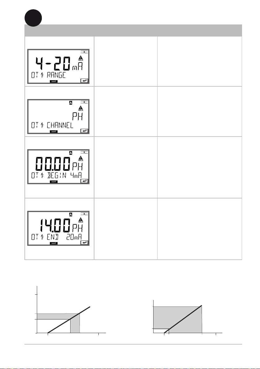
OT1: RANGE 0–20 mA, 4–20 mA 4-20 mA
CHANNEL
PH BEGIN 4 mA (0 mA) –2.00...16 PH 00.00 PH
END 20 mA –2.00...16 PH 14.00 PH
mV BEGIN 4 mA (0 mA) –1999...1999 mV
END 20 mA –1999...1999 mV
TMP A
°C
TMP A
°F
OXY
dO%
OXY
dO mg/l
OXY
do ppm
OXY
GAS %
TMP B
°C
TMP B
°F
FILTERTIME 0...120 SEC 0000 SEC
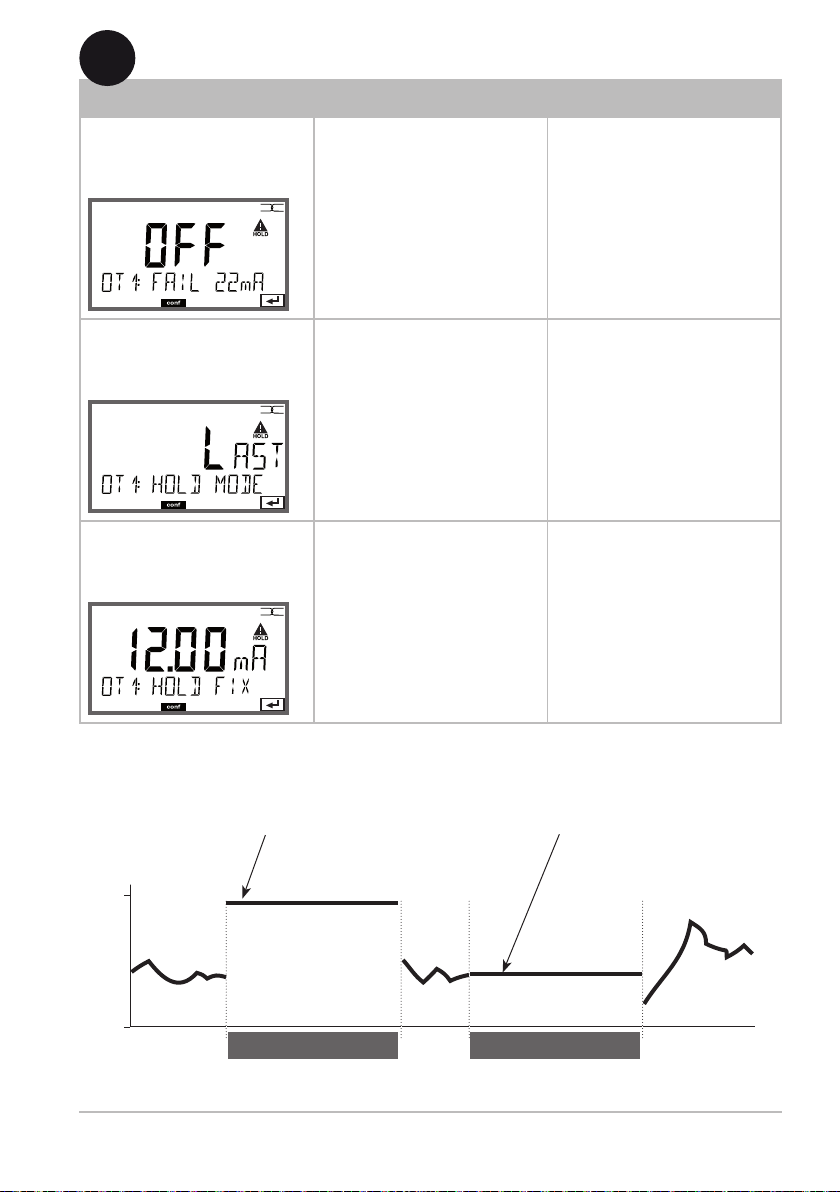
22mA-FAIL ON/OFF OFF
HOLD MODE LAST/FIX LAST
FIX HOLD-FIX (0) 4...22 mA 021.0 mA
BEGIN 4 mA (0 mA) –20...300 °C Select °C/°F
END 20 mA –20...300 °C at
BEGIN 4 mA (0 mA) –4...572 °F "MEAS MODE"
END 20 mA –4...572 °F
BEGIN 4 mA (0 mA) 000.0 ... 600.0 % 000.0 %
END 20 mA 000.0 ... 600.0% 150.0%
BEGIN 4 mA (0 mA) 000.0 µg/l .. 99.99 mg/l 00.00 µg/l
END 20 mA 000.0 µg/l .. 99.99 mg/l 20.00 mg/l
BEGIN 4 mA (0 mA) 000.0 ppb .. 99.99 ppm 000.0 ppb
END 20 mA 000.0 ppb .. 99.99 ppm 20.00 ppm
BEGIN 4 mA (0 mA) 000.0 ppm ... 99.99% 000.0 ppm
END 20 mA 000.0 ppm ... 99.99% 50.00%
BEGIN 4 mA (0 mA) –20...300 °C Select °C/°F
END 20 mA –20...300 °C
BEGIN 4 mA (0 mA) –4...572 °F
END 20 mA –4...572 °F
PH
at
"MEAS MODE"
32

Conguration
Conguration Choices Default
Alarm (ALARM)
ALA: DELAYTIME 0...600 SEC 0010 SEC
SENSOCHECK ON/OFF OFF
CONTROL IN ON/OFF OFF
Relay 1/2 (RL1/RL2)
REL: (Selected in text line) LIMITS, CONTROLLER LIMITS
RL1: CHANNEL PH / mV / TMP A /
OXY / TMP B
FUNCTION Lo LEVL, Hi LEVL Lo LEVL
CONTACT N/O, N/C N/O
LEVEL –2.00...16 PH
(-1999...1999 mV)
(-20...200°C)
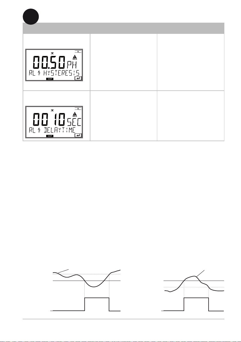
HYSTERESIS 0...10.00 PH 00.50 PH
DELAYTIME 0...9999 SEC 0010 SEC
RL2: CHANNEL PH / mV / TMP A /
OXY / TMP B
FUNCTION Lo LEVL, Hi LEVL Hi LEVL
CONTACT N/O, N/C N/O
LEVEL –2.00...16 PH
(–1999...1999 mV)
(–20...200°C)
HYSTERESIS 0...10.00 PH 00.50 PH
DELAYTIME 0...9999 SEC 0010 SEC
PH
00.00 PH
OXY
14.00 PH
33

Conguration
Conguration Choices Default
Relay 1/2 (RL1/RL2) -continued-
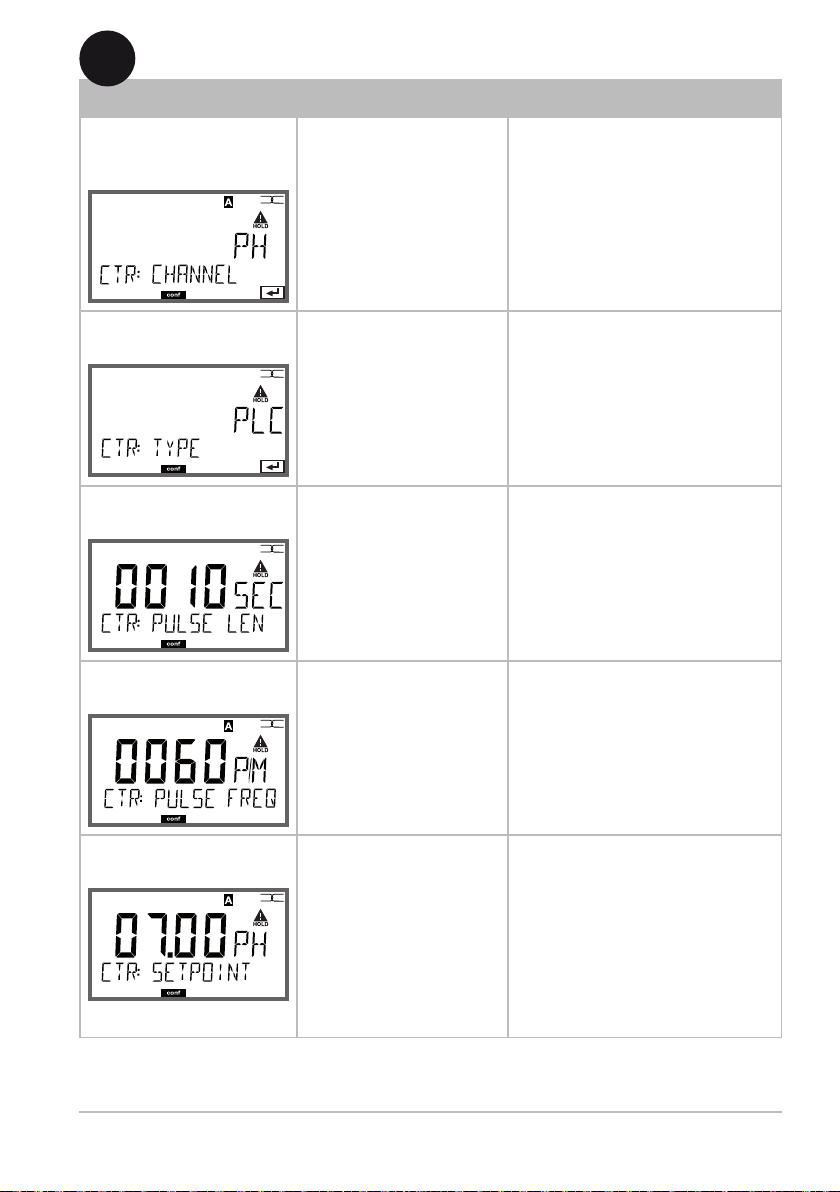
REL: CTR CHANNEL PH / mV / TMP A /
OXY / TMP B
TYPE PLC/PFC PLC
PLC PULSE LEN 0...0600 SEC 0010 SEC
PFC PULSE FREQ 0...0180 P/M 0060 P/M
SETPOINT –2.00...16 PH 07.00 PH
DEAD BAND 0...10.00 PH 01.00 PH
P-GAIN 10...9999% 0100%
I-TIME 0...9999 SEC 0000 SEC
D-TIME 0...9999 SEC 0000 SEC
HOLD MODE Y LAST/Y OFF Y LAST
Cleaning contact (WASH)
WSH: WASH CYCLE 0.0...999.9 h 000.0 h
WASH TIME 0...9999 SEC 0060 SEC
CONTACT N/O, N/C N/O
PH
Real-time clock (CLOCK)
CLK: FORMAT 24 h / 12 h
24 h TIME hh/mm 00..23:00...59
12 h TIME hh/mm 00...11 AM/
PM:00...59
DAY/MONTH 01...31/01...12
YEAR 2000...2099
Tag number (TAG)
TAG: (Input in text line) ___
1) These menu items are displayed only when the respective hardware is installed
and enabled.
34

Configuration (Original for Copy)
Please note:
Fill in your conguration data on the following pages or use them as
original for copy.
Parameter
PH: Sensor on/off
PH: Calibration mode
PH: Buffer set selection
PH: Calibration timer
PH: Calibration cycle
PH: TC-LIQUID
PH: CIP counter
PH: SIP counter
OXY: Sensor on/off
OXY: Calibration mode
OXY: Calibration timer
OXY: Calibration cycle
OXY: SALINITY
OXY: Pressure unit
OXY: PRESSURE MAN/EXT
OXY: EXT pressure correction
(I-INPUT: 0-20/4-20 mA)
I-INPUT: Start value
I-INPUT: End value
OXY: CIP counter
OXY: SIP counter
MES: Temperature unit
OT1: Current range
OT1: Channel
(process variable)
OT1: Current start
OT1: Current end
OT1: Filter time
OT1: 22 mA error current
OT1: HOLD mode
OT1: HOLD-FIX current
35

(Original for Copy) Conguration
Parameter
OT2: Current range
OT2: Channel
(process variable)
OT2: Current start
OT2: Current end
OT2: Filter time
OT2: 22 mA error current
OT2: HOLD mode
OT2: HOLD-FIX current
ALA: Delay
ALA: Sensocheck on/off
ALA: "Control" input
REL: Usage
RL1: Channel
(process variable)
RL1: Function
RL1: Contact response
RL1: Setpoint
RL1: Hysteresis
RL1: Delay
RL2: Channel
(process variable)
RL2: Function
RL2: Contact response
RL2: Setpoint
RL2: Hysteresis
RL2: Delay
CTR: Channel
(process variable)
CTR: Controller type
CTR: Pulse length
CTR: Pulse frequency
36

Conguration (Original for Copy)
Parameter
CTR: Setpoint
CTR: Neutral zone
CTR: P gain
CTR: I time
CTR: D time
CTR: HOLD mode
WSH: Wash cycle
WSH: Wash duration
WSH: Contact response
CLK: Time format
CLK: Time hh/mm
CLK: Day/month
CLK: Year
TAG: Tag number
37

Conguration
PH Sensor
Selecting pH sensor, calibration mode
1
2
3
4
5
enter
enter
meas
1 Press any arrow key.
2 Select CONF using keys, press enter.
3 Select SENSOR_PH menu using keys,
press enter,
SENS
MEMO
then select "MEAS_MODE = ON“.
Confirm by pressing enter.
4 All items of this menu group are indicated by
the “PH:” code.
Press enter to select menu,
edit using arrow keys (see next page).
Confirm (and proceed) using enter.
SENS
MEMO
5 End: Press meas key until the [meas] mode
indicator is displayed.
4
Select pH sensor
SENS
MEMO
Measuring channel on/off
Calibration mode
(AUTO: Buffer set)
Calibration timer
Calibration cycle
TC-LIQUID
Cleaning cycles
Sterilization cycles
enter
38

4
Conguration
Menu item Action Choices
Select sensor
Select sensor using
keys.
SENS
MEMO
Press enter to confirm.
SENSOR_PH
SENSOR_OXY
Measuring channel
MEMO
Calibration mode
MEMO
(AUTO: Buer set)
MEMO
Press enter to select "ON".
SENS
Switch to "OFF" if you do
not want to use this channel for measuring or if a
sensor is not connected.
Select CALMODE using
keys:
SENS
AUTO: Calibration with
Calimatic buffer set
recognition
MAN: Manual entry of
buffer solutions
DAT: Direct entry of
adjustment data
Press enter to confirm.
Select buffer set using
keys (see buffer
SENS
tables for nominal
values).
Press enter to confirm.
ON / OFF
AUTO
MAN
DAT
-00-...-09-, -U1-
Pressing the info key
displays the manufacturer
and nominal values in the
lower line.
39

Conguration
PH Sensor
Selecting cal timer, cal cycle
1
2
3
4
5
enter
enter
meas
1 Press any arrow key.
2 Select CONF using keys, press enter.
3 Select SENSOR_PH menu using keys,
press enter,
SENS
MEMO
then select "MEAS_MODE = ON“.
Confirm by pressing enter.
4 All items of this menu group are indicated by
the “PH:” code.
Press enter to select menu,
edit using arrow keys (see next page).
Confirm (and proceed) using enter.
SENS
MEMO
5 End: Press meas key until the [meas] mode
indicator is displayed.
4
Select pH sensor
SENS
MEMO
Measuring channel on/off
Calibration mode
(AUTO: Buffer set)
Calibration timer
Calibration cycle
TC-LIQUID
Cleaning cycles
Sterilization cycles
enter
40

4
Conguration
Menu item Action Choices
Calibration timer
MEMO
Calibration cycle
MEMO
Adjust CALTIMER using
keys:
SENS
OFF: No timer
ADAPT: Maximum cal
cycle (adjust in the next
step)
FIX: Fixed cal cycle
(adjust in the next step)
Press enter to confirm.
Only with FIX/ADAPT:
Modify digit using
SENS
keys, select next digit
using keys.
Press enter to confirm.
Note for the calibration timer:
When Sensocheck has been activated in the Conguration – Alarm
menu, the expiration of the calibration interval is indicated by
Sensoface:
OFF/ADAPT/FIX
With ADAPT, the calibration cycle is automatically
reduced depending on
the sensor load (high
temperatures and pH
values) and the sensor
wear.
0...9999 h
Display Status
+
+
The time remaining until the next due calibration can be seen in the
diagnostics menu (see Diagnostics chapter).
Over 80 % of the calibration interval has
already past.
The calibration interval has been exceeded.
41

Conguration
PH Sensor
Adjusting CIP cleaning cycles, SIP sterilization cycles
1
2
3
4
5
enter
enter
meas
1 Press any arrow key.
2 Select CONF using keys, press enter.
3 Select SENSOR_PH menu using keys,
press enter,
SENS
MEMO
then select "MEAS_MODE = ON“.
Confirm by pressing enter.
4 All items of this menu group are indicated by
the “PH:” code.
Press enter to select menu,
edit using arrow keys (see next page).
Confirm (and proceed) using enter.
SENS
MEMO
5 End: Press meas key until the [meas] mode
indicator is displayed.
4
Select pH sensor
SENS
MEMO
Measuring channel on/off
Calibration mode
(AUTO: Buffer set)
Calibration timer
Calibration cycle
TC-LIQUID
Cleaning cycles
Sterilization cycles
enter
42

4
Conguration
Menu item Action Choices
TC-LIQUID / CIP / SIP
Temp compensation,
process medium
Cleaning cycles
on/o
SENS
MEMO
Sterilization cycles
on/o
SENS
MEMO
For pH measurement
only: Enter temperature
compensation of the
process medium.
Enter value using
keys.
Press enter to confirm.
Select ON or OFF using
keys.
Activates/deactivates logging in extended logbook
Press enter to confirm.
Select ON or OFF using
keys.
Activates/deactivates logging in extended logbook
Press enter to confirm.
ON/OFF
ON/OFF
The cleaning and sterilization cycles are counted to measure the load
on the sensor.
Suitable for biochemical applications (process temp approx. 0...50 °C,
CIP temperature > 55 °C, SIP temperature > 115 °C).
43

Conguration
OXY Sensor
Selecting sensor type, measuring mode, calibration medium,
calibration timer
1
2
3
4
5
enter
enter
meas
1 Press any arrow key.
2 Select CONF using keys, press enter.
3 Select SENSOR_OXY menu using keys,
press enter.
SENS
MEMO
4 All items of this menu group are indicated by
the “OXY:” code.
Press enter to select menu,
edit with arrow keys (see next page).
Confirm (and proceed) by pressing enter.
5 End: Press meas key until the [meas] mode
indicator is displayed.
SENS
MEMO
4
Select sensor type
SENS
MEMO
Select measuring mode
Calibration medium water/air
Calibration timer
Salinity
Pressure unit
Pressure correction
Manual pressure correction
Current input
Current input/Pressure range
Cleaning cycles
Sterilization cycles
enter
44

4
Conguration
Menu item Action Choices
Select measuring
mode
Select measuring mode
using keys.
DO:
SENS
MEMO
Measurement in liquids
GAS:
Measurement in gases
Press enter to confirm.
dO %,
dO mg/l
dO ppm
GAS %
Calibration medium:
air/water
SENS
MEMO
Select calibration
medium using keys.
AIR: Cal medium air
CAL_AIR
CAL_WTR
WTR: Cal medium water
Press enter to confirm.
Calibration timer
Select/deselect
calibration timer using
SENS
MEMO
OFF
ON
keys.
Press enter to confirm.
(ON: Calibration
cycle)
Enter calibration cycle in
hours using
keys.
SENS
MEMO
0...9999 h
0168 h
Press enter to confirm.
Note for the calibration timer:
When Sensocheck has been activated in the Configuration – Alarm menu,
the expiration of the calibration interval is indicated by Sensoface:
Display Status
Over 80 % of the calibration interval has already past.
The time remaining until the next due calibration can
be seen in the diagnostics menu (see "Diagnostics").
The calibration interval has been exceeded.
45

Conguration
OXY Sensor
Selecting salinity, pressure unit, pressure correction
1
2
3
4
5
enter
enter
meas
1 Press any arrow key.
2 Select CONF using keys, press enter.
3 Select SENSOR_OXY menu using keys,
press enter.
SENS
MEMO
4 All items of this menu group are indicated by
the “OXY:” code.
Press enter to select menu,
edit with arrow keys (see next page).
Confirm (and proceed) by pressing enter.
5 End: Press meas key until the [meas] mode
indicator is displayed.
SENS
MEMO
4
Select sensor type
SENS
MEMO
Select measuring mode
Calibration medium water/air
Calibration timer
Salinity
Pressure unit
Pressure correction
Manual pressure correction
Current input
Current input/Pressure range
Cleaning cycles
Sterilization cycles
enter
46

4
Conguration
Menu item Action Choices
Enter salinity
Enter salinity of the
MEMO
Enter value using
process medium.
SENS
keys.
Press enter to confirm.
00.00...45.00 ppt
Enter pressure unit
Enter pressure
correction
(Manual pressure
input)
Select desired pressure
MEMO
Then, select manual
unit using keys.
SENS
or external pressure
correction.
Press enter to confirm.
Bar/kPa/PSI
MAN / EXT
(EXT with „External
current input“ option
only)
Select desired procedure
MAN / EXT
for pressure correction
using keys:
SENS
MEMO
MAN:
Manual specification
EXT:
Ext. pressure correction
via current input
Press enter to confirm.
Enter value using
keys.
SENS
MEMO
Input range:
0.000...9.999 BAR /
000.0...999.9 KPA /
000.0...145.0 PSI
1.013 BAR
Press enter to confirm.
Current input/
Pressure range
With external pressure
0(4)...20 mA
input, select current
MEMO
the pressure parameters
input 0/4 ... 20 mA and
SENS
for current start and end
0.000...9.999 Bar /
000.0...999.9 KPA /
000.0...999.9 PSI
using keys.
47

Conguration
OXY Sensor
Adjusting CIP cleaning cycles, SIP sterilization cycles
1
2
3
4
5
enter
enter
meas
1 Press any arrow key.
2 Select CONF using keys, press enter.
3 Select SENSOR_OXY menu using keys,
press enter.
SENS
MEMO
4 All items of this menu group are indicated by
the “OXY:” code.
Press enter to select menu,
edit with arrow keys (see next page).
Confirm (and proceed) by pressing enter.
5 End: Press meas key until the [meas] mode
indicator is displayed.
SENS
MEMO
4
Select sensor type
SENS
MEMO
Select measuring mode
Calibration medium water/air
Calibration timer
Salinity
Pressure unit
Pressure correction
Manual pressure correction
Current input
Current input/Pressure range
Cleaning cycles
Sterilization cycles
enter
48

4
Conguration
Menu item Action Choices
CIP / SIP
Cleaning cycles
on/o
Sterilization cycles
on/o
Select ON or OFF using
keys.
Activates/deactivates log-
SENS
MEMO
MEMO
ging in extended logbook
Press enter to confirm.
Select ON or OFF using
keys.
Activates/deactivates log-
SENS
ging in extended logbook
Press enter to confirm.
ON/OFF
ON/OFF
The cleaning and sterilization cycles are counted to measure the load
on the sensor.
Suitable for biochemical applications (process temp approx. 0...50 °C,
CIP temperature > 55 °C, SIP temperature > 115 °C).
49

Conguration
Measuring Mode
Specifying the temperature unit
1
2
3
4
enter
enter
1 Press any arrow key.
2 Select CONF using keys, press enter.
3 Select MEAS_MODE menu using keys,
press enter.
SENS
MEMO
4 All items of this menu group are indicated by
the “MES:” code.
Press enter to select menu,
edit using arrow keys (see next page).
Confirm (and proceed) using enter.
5 End: Press meas key until the [meas] mode
indicator is displayed.
SENS
MEMO
4
Temperature unit
SENS
MEMO
enter
5
50
meas

4
Conguration
Menu item Action Choices
Temperature unit
Select °C or °F using
keys.
SENS
MEMO
Press enter to confirm.
°C / °F
51

Conguration
Current Output 1
Selecting the output current range
1
2
3
4
5
enter
enter
meas
1 Press any arrow key.
2 Select CONF using keys, press enter.
3 Select OUT1 menu using keys, press
enter.
SENS
MEMO
SENS
MEMO
4 All items of this menu group are indicated by
the “OT1:” code.
Press enter to select menu,
edit using arrow keys (see next page).
Confirm (and proceed) using enter.
5 End: Press meas key until the [meas] mode
indicator is displayed.
4
Current range
SENS
MEMO
Process variable
enter
Current start
Current end
Time averaging lter
Output current during error
message
Output current during HOLD
52
Output current for HOLD FIX
4
Conguration
Menu item Action Choices
Current range
Select 4-20 mA or
0-20 mA range using
SENS
MEMO
keys.
Press enter to confirm.
4-20 mA / 0-20 mA
Process variable
Current start
Current end
Select using
keys:
SENS
MEMO
PH: pH value
TMP: Temperature
OXY: Dissolved oxygen
Press enter to confirm.
Modify digit using
keys,
SENS
MEMO
select next digit using
keys.
Press enter to confirm.
Enter value using
keys.
SENS
MEMO
Press enter to confirm.
PH / mV / TMP A /
OXY / TMP B/
–2...16 pH (PH)
–1999...1999 mV (ORP)
–20...300°C/–4...572 °F (TMP A)
000.0 … 600.0 % (OXY dO%)
000.0 μg/l… 99.99 mg/l (OXY)
000.0 ppb… 99.99 ppm (OXY)
-000.0 ppm … 99.99 % (OXY)
–20...300°C/–4...572 °F (TMP B)
–2...16 pH (PH)
–1999...1999 mV (ORP)
–20...300°C/–4...572 °F (TMP A)
000.0 … 600.0 % (OXY dO%)
000.0 μg/l… 99.99 mg/l (OXY)
000.0 ppb… 99.99 ppm (OXY)
-000.0 ppm … 99.99 % (OXY)
–20...300°C/–4...572 °F (TMP B)
Assignment of measured values: Current start and current end
Example 1: Range pH 0...14
[pH]
14
7
5
Output current
0
[mA]
20 4
Example 2: Range pH 5...7
Advantage: Higher resolution in
[pH]
range of interest
7
5
Output current
20 4
[mA]
53

Conguration
Current Output 1
Adjusting time interval of output lter
1
2
3
4
5
enter
enter
meas
1 Press any arrow key.
2 Select CONF using keys, press enter.
3 Select OUT1 menu using keys, press
enter.
SENS
MEMO
SENS
MEMO
4 All items of this menu group are indicated by
the “OT1:” code.
Press enter to select menu,
edit using arrow keys (see next page).
Confirm (and proceed) using enter.
5 End: Press meas key until the [meas] mode
indicator is displayed.
4
Current range
SENS
MEMO
Process variable
enter
Current start
Current end
Time averaging lter
Output current during error
message
Output current during HOLD
54
Output current for HOLD FIX

4
Conguration
Menu item Action Choices
Time averaging lter
MEMO
Enter value using
keys.
SENS
Press enter to confirm.
Time averaging lter
To smoothen the current output, a low-pass lter with adjustable lter
time constant can be switched on. When there is a jump at the input
(100 %), the output level is at 63 % after the time interval has been
reached. The time interval can be set from 0 to 120 sec. If the time
interval is set to 0 sec, the current output directly follows the input.
Please note:
The lter only acts on the current output, not on the display, the limit
values or the controller!
During HOLD the lter is not applied. This prevents a jump at the
output.
0...120 SEC
(0000 SEC)
pH
Temp
Display / Controller
0/4-20 mA
Time interval 0...120 s
Time interval 0...120 s
55

Conguration
Current Output 1
Output current during Error and HOLD
1
2
3
4
5
enter
enter
meas
1 Press any arrow key.
2 Select CONF using keys, press enter.
3 Select OUT1 menu using keys, press
enter.
SENS
MEMO
SENS
MEMO
4 All items of this menu group are indicated by
the “OT1:” code.
Press enter to select menu,
edit using arrow keys (see next page).
Confirm (and proceed) using enter.
5 End: Press meas key until the [meas] mode
indicator is displayed.
4
Current range
SENS
MEMO
Process variable
enter
Current start
Current end
Time averaging lter
Output current during error
message
Output current during HOLD
56
Output current for HOLD FIX
4
Conguration
Menu item Action Choices
Output current during error message
MEMO
Select ON or OFF using
keys.
Press enter to confirm.
SENS
ON/OFF
Output current
during HOLD
LAST: During HOLD the
last measured value is
maintained at the output.
SENS
MEMO
FIX: During HOLD a value
(to be entered) is maintained at the output.
Select using
Press enter to confirm.
Output current for
HOLD FIX
Only with FIX selected:
Enter current which is to
flow at the output during
SENS
MEMO
HOLD
Enter value using
keys.
Press enter to confirm.
Output signal during HOLD:
Output current
[mA]
21
Output signal for HOLD
FIX setting = 21.0 mA
LAST/FIX
00.00...22.00 mA
(21.00 mA)
Output signal for HOLD
LAST setting
4
HOLD active
HOLD active
57

Conguration
Current Output 2
Selecting the output current range
1
2
3
4
5
enter
enter
meas
1 Press any arrow key.
2 Select CONF using keys, press enter.
3 Select OUT2 menu using keys, press
enter.
SENS
MEMO
SENS
MEMO
4 All items of this menu group are indicated by
the “OT2:” code.
Press enter to select menu,
edit using arrow keys (see next page).
Confirm (and proceed) using enter.
5 End: Press meas key until the [meas] mode
indicator is displayed.
4
Current range
SENS
MEMO
Process variable
enter
Current start
Current end
Time averaging lter
Output current during error
message
Output current during HOLD
58
Output current for HOLD FIX

4
Conguration
Menu item Action Choices
Current range
Select 4-20 mA or
0-20mA range using
SENS
MEMO
keys.
Press enter to confirm.
4-20 mA / 0-20 mA
Process variable
Select using keys:
PH: pH value
SENS
MEMO
TMP: Temperature
OXY: Dissolved oxygen
Press enter to confirm.
PH / mV / TMP A /
OXY / TMP B/
.
.
.
All the following adjustments are made as for current output 1
(see there)!
59

Conguration
Alarm Settings
Delay, Sensocheck, CONTROL input
1
2
3
4
5
enter
enter
meas
1 Press any arrow key.
2 Select CONF using keys, press enter.
3 Select ALARM menu using keys,
press enter.
SENS
MEMO
4 All items of this menu group are indicated by
the “ALA:” code.
Press enter to select menu,
edit using arrow keys (see next page).
Confirm (and proceed) using enter.
5 End: Press meas key until the [meas] mode
indicator is displayed.
SENS
MEMO
SENS
MEMO
4
Delay
enter
Sensocheck
CONTROL input
Error messages can be signaled by a 22 mA output current (see Error Messages and
Configuration of Output 1/Output 2). The alarm contact opens.
The alarm delay time delays the color change of the display backlighting to red,
the 22 mA signal (if configured), and the alarm contact switching.
60

4
Conguration
Menu item Action Choices
Delay
Enter value using
keys.
SENS
MEMO
Press enter to confirm.
0...600 SEC
010 SEC)
Sensocheck
CONTROL input
Select Sensocheck
ON/OFF
(continuous monitoring
SENS
MEMO
of sensor).
Select ON or OFF using
keys.
Press enter to confirm.
Activate CONTROL input
ON/OFF
(switches alarm contact),
SENS
MEMO
e.g. for evaluating an
external flow monitoring.
Select ON or OFF using
keys.
Press enter to confirm.
61

Conguration
Limit Function
Relay 1
1
2
3
4
enter
enter
enter
1 Press any arrow key.
2 Select CONF using keys, press enter.
3 Select REL1/REL2 menu using keys,
press enter, then select LIMITS.
SENS
MEMO
4 All items of this menu group are indicated by
the “RL1:” code.
Press enter to select menu,
edit using arrow keys (see next page).
Confirm (and proceed) using enter.
5 End: Press meas key until the [meas] mode
indicator is displayed.
SENS
MEMO
SENS
MEMO
4
Use of relays
enter
Select process variable
Limit 1 switching characteristics
SENS
MEMO
(function)
Limit 1 contact type
5
62
Limit 1 setpoint
Limit 1 hysteresis
Limit 1 delay
meas

4
Conguration
Menu item Action Choices
Use of relays
Select in the text line
using keys:
SENS
MEMO
• Limit function
(LIMITS)
• Controller
(CONTROLLER)
Press enter to confirm.
LIMITS / CONTROLLER
Please note: Selecting
CONTROLLER leads to
Controller menu group CTR.
Select process
variable
Limit 1 function
Limit 1 contact
response
Limit 1 setpoint
Select desired process
variable using
keys.
SENS
MEMO
Press enter to confirm.
Select desired function
using arrow keys.
SENS
MEMO
LoLevel: active if value
falls below setpoint
HiLevel: active if value
exceeds setpoint
Press enter to confirm.
N/O: normally open
contact
N/C: normally closed
SENS
MEMO
contact
Select using keys.
Press enter to confirm.
Enter setpoint using
SENS
MEMO
keys.
Press enter to confirm.
PH / mV / TMP A /
OXY / TMP B/
Lo LEVL / Hi LEVL
N/O / N/C
–2...16 pH (PH)
–1999...1999 mV (ORP)
000.0 … 600.0 % (OXY dO%)
000.0 μg/l… 99.99 mg/l (OXY)
000.0 ppb… 99.99 ppm (OXY)
-000.0 ppm … 99.99 % (OXY)
–20...300°C/–4...572 °F (TMP )
63

Conguration
Limit Function
Relay 1
1
2
3
4
enter
enter
enter
1 Press any arrow key.
2 Select CONF using keys, press enter.
3 Select REL1/REL2 menu using keys,
press enter, then select LIMITS.
SENS
MEMO
4 All items of this menu group are indicated by
the “RL1:” code.
Press enter to select menu,
edit using arrow keys (see next page).
Confirm (and proceed) using enter.
5 End: Press meas key until the [meas] mode
indicator is displayed.
SENS
MEMO
SENS
MEMO
4
Use of relays
enter
Select process variable
Limit 1 switching characteristics
SENS
MEMO
(function)
Limit 1 contact type
5
64
Limit 1 setpoint
Limit 1 hysteresis
Limit 1 delay
meas
4
Conguration
Menu item Action Choices
Limit 1 hysteresis
Limit 1 delay
Select hysteresis using
keys.
SENS
MEMO
Press enter to confirm.
The contact is activated
with delay (deactivated
SENS
MEMO
without delay)
Adjust delay using
keys.
Press enter to confirm.
0...10.00 PH
(00.50 PH)
0...9999 SEC
(0010 SEC)
Limit Lo
Hysteresis +
Setpoint
Contact
Limit Hi
Signal
Setpoint
Hysteresis -
1
Contact
0
1
0
Signal
65

Conguration
Limit Function
Relay 2
1
2
3
4
enter
enter
enter
1 Press any arrow key.
2 Select CONF using keys, press enter.
3 Select REL1/REL2 menu using keys,
press enter.
SENS
MEMO
4 All items of this menu group are indicated by
the “RL2:” code.
Press enter to select menu,
edit using arrow keys (see next page).
Confirm (and proceed) using enter.
5 End: Press meas key until the [meas] mode
indicator is displayed.
SENS
MEMO
SENS
MEMO
4
Use of relays
enter
Select process variable
Limit 2 switching characteristics
SENS
MEMO
(function)
Limit 2 contact type
5
66
Limit 2 setpoint
Limit 2 hysteresis
Limit 2 delay
meas

4
Conguration
Menu item Action Choices
Select process
variable
(CHANNEL)
Limit 2
function
(FUNCTION)
Limit 2 contact
type
(CONTACT)
Limit 2 setpoint
(LEVEL)
Select desired process
variable using keys.
Press enter to confirm.
Select desired function
using arrow keys.
Press enter to confirm.
N/O: normally open
contact
N/C: normally closed
contact
Select using
Press enter to confirm.
Enter setpoint using
keys.
Press enter to confirm.
PH / mV / TMP A /
OXY / TMP B/
Lo LEVL / Hi LEVL
N/O / N/C
–2...16 pH (PH)
–1999...1999 mV (ORP)
000.0 … 600.0 % (OXY dO%)
000.0 μg/l… 99.99 mg/l (OXY)
000.0 ppb… 99.99 ppm (OXY)
-000.0 ppm … 99.99 % (OXY)
–20...300°C/–4...572 °F (TMP )
Limit 2 hysteresis
(HYSTERESIS)
Limit 2 delay
(DELAYTIME)
Limit Lo
Hysteresis +
Setpoint
1
Contact
0
Select hysteresis using
keys.
Press enter to confirm.
The contact is activated
with delay (deactivated
without delay)
Adjust delay using
keys.
Press enter to confirm.
Signal
0...10.00 PH
(00.50 PH)
0...9999 SEC
(0010 SEC)
Limit Hi
Signal
Setpoint
Hysteresis -
1
Contact
0
67

68

Controller Functions
Typical Applications
P controller
Application for integrating control systems
(e.g. closed tank, batch processes).
PI controller
Application for non-integrating control systems (e.g. drains).
PID controller
The additional derivative action compensates for measurement peaks.
Controller Characteristic
Relay 1
+100%
Setpoint
-100%
Controller output
Yp [%]
Neutral zone Yp=0
Deviation Xw [pH]
Relay 2
69

Controller Functions
Controller equations
Controller output Y =
YP + YPdt + T
P action
1
T
R
I action D action
with:
Proportional action
Reset time [s]
Rate time [s]
Controller gain [%]
500 mV (for ORP)
5.00 mg/l (for mg/l)
Proportional action Y
Setpoint - Meas. value
Y
=
P
Constant
Y
P
T
R
T
D
K
C
P
*
PH constant 5 (for pH)
K
OXY constant 50% (for %O
C
5.00 ppm (for ppm)
Neutral zone
Tolerated deviation from desired value.
With the setting “1 pH”, for example, a deviation of ± 0.5 pH
from the desired value is tolerated.
Proportional action (Gradient KC [%])
100%
KC = 500 %
KC = 200 %
dY
P
D
dt
or %Air)
2
PH
OXY
70
Controller
output Y
50 %
X
Deviation
X
Deviation
KC = 100 %
KC = 50 %
w
1 / (100) 2 / (200) 3 / (300) 4 / (400)
5 / (500)
[10] [20] [30] [40] [50]
Process variables: pH/ (mV),
underneath: temp [K]
w
10 / (1.00)
20 / (2.00) 30 / (3.00) 40 / (4.00) 50 / (5.00)
[10] [20] [30] [40] [50]
Process variables: % (mg/l, ppm or GAS),
underneath: temp [K]

Controller Functions
Pulse Length / Pulse Frequency Controller
Pulse length controller (PLC)
The pulse length controller is used to operate a valve as an actuator.
It switches the contact on for a time that depends on the controller
output. The period is constant. A minimum ON time of 0.5 sec is
maintained even if the controller output takes corresponding values.
Output signal (relay contact) of pulse length controller
ON time (Y = 20 %)
1
0
1
0
Pulse frequency controller (PFC)
The pulse frequency controller is used to operate a frequencycontrolled actuator (metering pump). It varies the frequency with
which the contacts are switched on. The maximum pulse frequency
[pulses/min] can be defined. It depends on the actuator.
The contact ON time is constant. It is automatically calculated from
the user-defined maximum pulse frequency:
ON time (Y = 80 %)
Pulse length
Output signal (relay contact) of pulse frequency controller
ON time
1
0
Pulse frequency (Y = 20%)
1
0
Pulse frequency (Y = 80%)
71

Conguration
Controller
(For description, see Controller Functions)
Process variable, controller type, setpoint.
1
2
3
enter
enter
enter
1 Press any arrow key.
2 Select CONF using keys, press enter.
3 Select REL1/REL2 menu using keys,
press enter, then select CONTROLLER.
SENS
MEMO
4 All items of this menu group are indicated by
the “CTR:” code.
Press enter to select menu,
edit using arrow keys (see next page).
Confirm (and proceed) using enter.
5 End: Press meas key until the [meas] mode
indicator is displayed.
SENS
MEMO
SENS
MEMO
4
Use of relays
enter
Select process variable
Controller type
4
5
72
meas
SENS
MEMO
Pulse length
Pulse frequency
Setpoint
Neutral zone
Controller: P action
Controller: I action
Controller: D action
Behavior during HOLD
4
Conguration
Menu item Action Choices
Select process
variable
Select desired process
variable using
keys.
SENS
MEMO
Press enter to confirm.
PH / mV / TMP A /
OXY / TMP B/
Controller type
Pulse length
Pulse frequency
Setpoint
Pulse length controller
(PLC)
SENS
MEMO
or pulse frequency
controller (PFC)
Select using
keys.
Press enter to confirm.
Only with PLC:
Pulse length
SENS
MEMO
Adjust using
keys.
Press enter to confirm.
Only with PFC:
Pulse frequency
SENS
MEMO
Adjust using
keys.
Press enter to confirm.
Adjust setpoint using
keys.
SENS
MEMO
Press enter to confirm.
PLC/PFC
0...0600 SEC
0010 SEC)
0...0180 P/M
(0060 P/M)
(pulses per minute)
–2...16 pH (PH)
–1999...1999 mV (ORP)
000.0 … 600.0 % (OXY dO%)
000.0 μg/l… 99.99 mg/l (OXY)
000.0 ppb… 99.99 ppm (OXY)
-000.0 ppm … 99.99 % (OXY)
–20...300°C/–4...572 °F (TMP )
73

Conguration
Controller
(For description, see Controller Functions)
Neutral zone. P, I, D actions. Behavior during HOLD
1
2
3
enter
enter
enter
1 Press any arrow key.
2 Select CONF using keys, press enter.
3 Select REL1/REL2 menu using keys,
press enter, then select CONTROLLER.
SENS
MEMO
4 All items of this menu group are indicated by
the “CTR:” code.
Press enter to select menu,
edit using arrow keys (see next page).
Confirm (and proceed) using enter.
5 End: Press meas key until the [meas] mode
indicator is displayed.
SENS
MEMO
SENS
MEMO
4
Use of relays
enter
Select process variable
Controller type
4
5
74
meas
SENS
MEMO
Pulse length
Pulse frequency
Setpoint
Neutral zone
Controller: P action
Controller: I action
Controller: D action
Behavior during HOLD

4
Conguration
Menu item Action Choices
Neutral zone
Adjust neutral zone using
SENS
MEMO
keys.
PH:
0...10.00 PH
(01.00 PH) /
0...2000 mV
Controller: P action
MEMO
Controller: I action
MEMO
Controller: D action
MEMO
Behavior during
HOLD
MEMO
Press enter to confirm.
OXY:
0 ... 50% full scale
Adjust P action using
SENS
keys.
10...9999%
(0100%)
Press enter to confirm.
Adjust I action using
SENS
keys.
0...9999 SEC
(0000 SEC)
0000 = no integral action
Press enter to confirm.
Adjust D action using
SENS
keys.
0...9999 SEC
(0000 SEC)
0000 = no diferential action
Press enter to confirm.
Select response using
Y LAST / Y OFF
keys.
Press enter to confirm.
SENS
During HOLD, the control loop is interrupted, the
controller has no reference signal or the reference
signal is frozen.
Y LAST: During HOLD, the controller keeps running
with its last setting (advisable for non-integrating
control systems)
Y OFF: The controller is switched off (advisable for
integrating control systems)
75

Conguration
WASH Contact
Controlling a rinsing probe
1
2
3
4
enter
enter
meas
1 Press any arrow key.
2 Select CONF using keys, press enter.
3 Select WASH menu using keys, press
enter.
SENS
MEMO
4 All items of this menu group are indicated by
the “WSH:” code.
Press enter to select menu,
edit using arrow keys (see next page).
Confirm (and proceed) using enter.
5 End: Press meas key until the [meas] mode
indicator is displayed.
SENS
MEMO
SENS
MEMO
4
Cleaning interval
enter
Cleaning duration
Contact type
5
76

4
Conguration
Menu item Action Choices
Cleaning interval
Adjust value using
keys.
SENS
MEMO
Press enter to confirm.
0.0...999.9 h (000.0 h)
Cleaning duration
Contact type
Cleaning Relax time (approx. 20 s)
Adjust value using
keys.
SENS
MEMO
0...9999 SEC (0060 SEC)
Press enter to confirm.
N/O: normally open
N/O / N/C
contact
SENS
MEMO
N/C: normally closed
contact
Select using keys.
Press enter to confirm.
Cycle interval
HOLD
77

Conguration
Time and Date
Tag Number
1
2
3
4
5
enter
enter
meas
1 Press any arrow key.
2 Select CONF using keys, press enter.
3 Select CLOCK or TAG using keys, press
enter.
SENS
MEMO
4 All items of this menu group are indicated by
the “CLK:” or “TAG” code.
Press enter to select menu,
edit using arrow keys (see next page).
Confirm (and proceed) using enter.
5 End: Press meas key until the [meas] mode
indicator is displayed.
SENS
MEMO
SENS
MEMO
Time format
4
enter
Time
Day and month
Year
78
Tag number

Conguration
Time and Date
In measuring mode the time is shown in the lower display.
In addition, the logbook entries (cf Diagnostics) are provided with a
time stamp.
Please note:
• After prolonged power outage (> 5 days) the time display is
replaced by dashes and cannot be used for processing.
Enter the correct time.
• There is no automatic switchover from winter to summer time!
Be sure to manually adjust the time!
Tag Number (“TAG“)
You can enter a designation for the point of measurement (tag
number) in the lower display line. Up to 32 digits are possible.
Pressing meas (repeatedly) in the measuring mode indicates the tag
number.
Being part of the device conguration, the “TAG“ can be read out via
IrDA. A standardized tag number helps, for example, to correctly reinstall a device after repair.
4
Menu item Action Choices
Tag number
Select character using
keys,
SENS
MEMO
select next digit using
keys.
Press enter to confirm.
A...Z, 0...9, – + < > ? / @
The first 10 characters are
seen in the display without scrolling.
79

PH Calibration
Please note:
• All calibration procedures must be performed by trained personnel.
Incorrectly set parameters may go unnoticed, but change the
measuring properties.
• The response time of the sensor and temperature probe is
considerably reduced when the sensor is rst moved about in the
buer solution and then held still.
• The device can only operate properly when the buer solutions
used correspond to the congured set. Other buer solutions, even
those with the same nominal values, may demonstrate a dierent
temperature response. This leads to measurement errors.
When using an ISFET Memosens sensor, the nominal zero point
must be adjusted each time a new sensor is connected.
This is important if you want to obtain reliable Sensoface messages.
The Sensoface messages issued during all further calibrations are
based on this basic calibration.
Pre-Calibrating Memosens Sensors
Memosens sensors have an integrated data storage and are clearly
identiable with TAGs (label, e.g. point of measurement). Therefore,
they can be easily pre-calibrated in the lab. This is particularly useful
when there are several points of measurement in the process.
80

Selecting a Calibration Mode
Calibration is used to adapt the device to the individual sensor
characteristics, namely asymmetry potential and slope.
Access to calibration can be protected with a passcode (SERVICE
menu). First, open the calibration menu and select the sensor
(SENSOR_PH) and then the calibration mode:
SENSOR_PH Calibrating the pH sensor
CAL_PH Adjusting the pH
P_CAL Product calibration
(calibration with sampling)
ISFET-ZERO ISFET operating point
(displayed only when ISFET Memosens
sensor is connected)
To preset CAL_PH (CONF menu / conguration):
1) Hold meas key depressed (> 2 s) (measuring mode)
2) Press any arrow key: the selection menu appears
3) Select CONF mode using left / right arrow key
4) Select “SENSOR“ – “CALMODE“: AUTO, MAN, or DAT.
Press enter to conrm.
Selection menu
SENS
MEMO
Selected mode
(blinks)
1
2
3
4
81
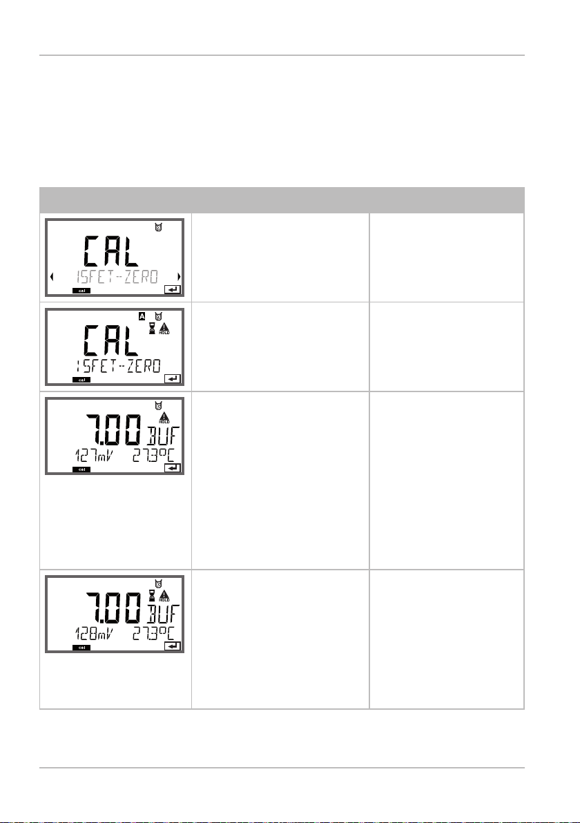
Zero adjustment
Zero Adjustment (ISFET)
This adjustment allows the use of ISFET Memosens sensors. The function is available when an ISFET Memosens sensor is connected.
The adjustment is made using a zero buer (pH 7.00).
Permitted range for buer value: pH 6.5 ... 7.5.
Maximum zero oset: ±750 mV
Display Action Remark
Select Calibration.
Press enter to proceed.
Ready for calibration.
Hourglass blinks.
Immerse sensor in a pH
7.00 buer. Enter the
temperature-corrected
pH value in the range
6.50 to 7.50 using the
arrow keys .
Press enter to conrm.
Stability check.
The measured value
[mV] is displayed.
The “hourglass” icon is
blinking.
Display (3 sec)
Now the device is in
HOLD mode.
If the zero oset of
the sensor is too
large (> ± 750mV), a
CAL ERR error message is generated. In
that case the sensor
cannot be calibrated.
At 500 mV Sensoface
becomes sad.
Please note:
Stability check can
be stopped (by
pressing enter).
However, this reduces calibration
accuracy.
82

Zero Adjustment (ISFET)
Display Action Remark
At the end of the adjustment procedure
the zero oset [mV] of
the sensor is displayed
(based on 25 °C).
Sensoface is active.
Press enter to proceed.
Use the arrow keys to
select:
• Repeat
(repeat calibration) or
• Measuring.
Press enter to conrm.
Place sensor in process.
End zero calibration
with enter.
This is not the nal
calibration value of
the sensor!
Asymmetry potential and slope must
be determined with
a complete 2-point
calibration.
After end of calibration, the outputs remain in HOLD mode
for a short time.
Note for Zero Adjustment
After having adjusted the zero oset, be sure to calibrate the sensor
following one of the procedures as described on the next pages.
83

Adjustment (Calimatic)
Automatic Calibration (Calimatic)
The AUTO calibration mode must have been preset during conguration. Make sure that the buer solutions used correspond to the con-
gured buer set. Other buer solutions, even those with the same
nominal values, may demonstrate a dierent temperature response.
This leads to measurement errors.
Display Action Remark
SENS
MEMO
Select Calibration.
Press enter to proceed.
Ready for calibration.
Hourglass blinks.
Select calibration
method: CAL_PH
Press enter to proceed.
Remove the sensor,
clean it, and immerse it
in the rst buer solution (it does not matter
which solution is taken
rst). Press enter to
start.
Buer recognition.
While the “hourglass”
icon is blinking, the
sensor remains in the
rst buer solution.
Buer recognition
terminated, the nominal buer value is
displayed.
Display (3 sec)
Now the device is in
HOLD mode.
To reduce the sensor
response time, rst
move it about in the
buer solution and
then hold it still.
84

Automatic Calibration (Calimatic)
Display Action Remark
At the end of the stability check, the value will
be saved and the asymmetry potential will be
displayed.
Calibration with the rst
buer is terminated.
Remove the sensor
from the rst buer
solution and rinse it
thoroughly.
Use the arrow keys to
select:
• END (1-point cal)
• CAL2 (2-point cal)
• REPEAT
Press enter to proceed.
2-point calibration:
Immerse the sensor
in the second buer
solution.
Press enter to start.
Retract sensor out of
second buer, rinse o,
re-install.
Press enter to proceed.
Please note:
Stability check can
be stopped after
10 sec (by pressing
enter). However, this
reduces calibration
accuracy. Display for
1-point cal:
Sensoface is active.
End by pressing
enter
The calibration
process runs as for
the rst buer.
The slope and asymmetry potential of
the sensor (based on
25 °C) are displayed.
Use the arrow keys to
select:
• MEAS (end)
• REPEAT
Press enter to proceed.
End: HOLD is deactivated with delay.
When 2-point cal is
ended:
85

Manual Calibration with Buffer Entry
The MAN calibration mode must have been preset during conguration. For calibration with manual buer specication, you must enter
the pH value of the buer solution used in the device for the proper
temperature. Any desired buer solution can be used for calibration.
Display Action Remark
Select Calibration.
Press enter to proceed.
Ready for calibration.
Hourglass blinks.
Remove the sensor,
clean it, and immerse
it in the rst buer
solution.
Press enter to start.
Enter the pH value of
your buer solution for
the proper temperature.
While the “hourglass”
icon is blinking, the
sensor remains in the
rst buer solution.
Display (3 sec)
Now the device is in
HOLD mode.
To reduce the sensor
response time, rst
move it about in the
buer solution and
then hold it still.
86
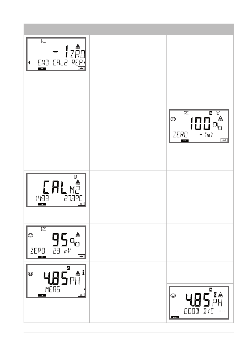
Manual Calibration with Buer Entry
Display Action Remark
At the end of the stability check, the value
will be saved and the
asymmetry potential
will be displayed.
Calibration with the rst
buer is terminated.
Remove the sensor from
the rst buer solution
and rinse it thoroughly.
Use the arrow keys to
select:
• END (1-point cal)
• CAL2 (2-point cal)
• REPEAT
Press enter to proceed.
2-point calibration:
Immerse sensor in
second buer solution.
Enter pH value.
Press enter to start.
Please note:
Stability check can
be stopped after
10 sec (by pressing
enter). However, this
reduces calibration
accuracy. Display for
1-point cal:
Sensoface is active.
End by pressing
enter
The calibration
process runs as for
the rst buer.
Rinse o and re-install
the sensor.
Press enter to proceed.
Use the arrow keys to
select:
• MEAS (end)
• REPEAT
Press enter to proceed.
End: HOLD is deactivated with delay.
Display of slope and
new asymmetry
potential (based on
25 °C).
When 2-point cal is
ended:
87
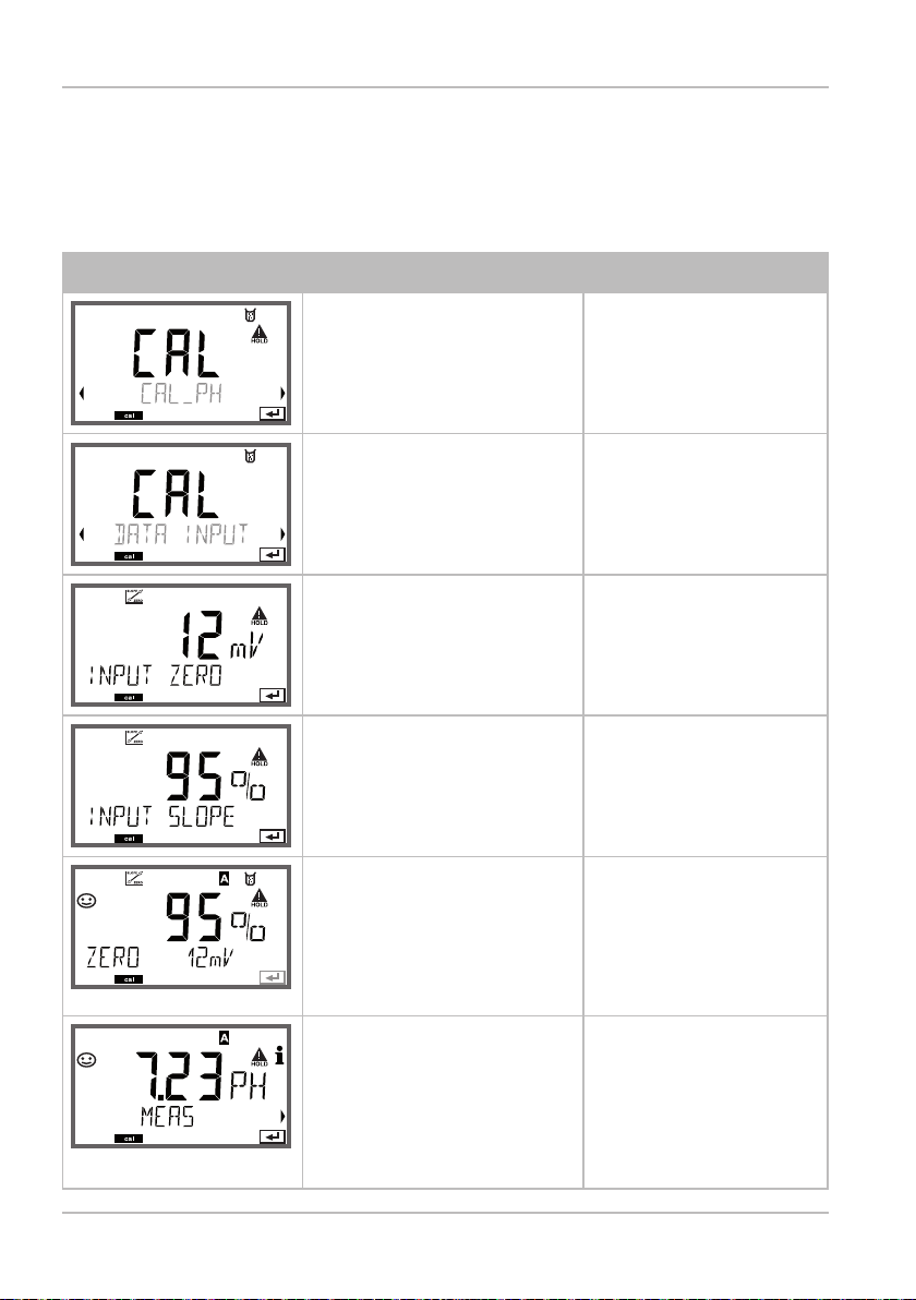
Data Entry of Premeasured Sensors
The DAT calibration mode must have been preset during
conguration.
You can directly enter the values for slope and asymmetry potential
of a sensor. The values must be known.
Display Action Remark
Select Calibration.
Press enter to proceed.
“Data Input“
Ready for calibration.
Hourglass blinks.
Enter asymmetry
potential [mV].
Press enter to proceed.
Enter slope [%].
The device displays
the new slope and
asymmetry potential
(at 25 °C).
Sensoface is active.
Use the arrow keys to
select:
• MEAS (end)
• REPEAT
Press enter to proceed.
Display (3 sec)
Now the device is in
HOLD mode.
End:
HOLD is deactivated
with delay.
88

Converting Slope to mV
Converting slope [%] to slope [mV/pH] at 25 °C
% mV/pH
78 46.2
80 47.4
82 48.5
84 49.7
86 50.9
88 52.1
90 53.3
92 54.5
94 55.6
96 56.8
98 58.0
100 59.2
102 60.4
Converting asymmetry potential to sensor zero point
V
[mV]
ZERO = 7 -
AS
S [mV / pH]
ZERO
V
AS
S
= Sensor zero
= Asymmetry potential
= Slope
89

Product calibration
Product Calibration (pH)
Calibration by sampling (one-point calibration).
During product calibration the sensor remains in the process.
The measurement process is only interrupted briey.
Procedure:
1) The sample is measured in the lab or directly on the site using a
portable meter. To ensure an exact calibration, the sample temperature must correspond to the measured process temperature.
During sampling the device saves the currently measured value and
then returns to measuring mode. The “calibration“ mode indicator
blinks.
2) In the second step you enter the measured sample value in the
device. From the dierence between the stored measured value and
entered sample value, the device calculates the new asymmetry
potential.
If the sample is invalid, you can take over the value stored during
sampling. In that case the old calibration values are stored.
Afterwards, you can start a new product calibration.
Display Action Remark
Select product
calibration: P_CAL.
Press enter to proceed.
Ready for calibration.
Hourglass blinks.
Take sample and save
value.
Press enter to proceed.
Display (3 sec)
Now the device is in
HOLD mode.
Now the sample can
be measured.
90

Product Calibration (pH)
Display Action Remark
Calibration is
terminated.
The device returns to
measuring mode.
Product calibration
step2
The stored value is
displayed (blinking) and
can be overwritten with
the measured sample
value.
Press enter to proceed.
Display of new
asymmetry potential
(based on 25°C).
Sensoface is active.
To end calibration:
Select MEAS, then
enter
After end of calibration, the outputs remain in
HOLD mode for a short time.
From the blinking
CAL mode indicator
you see that product
calibration has not
been terminated.
Display (3 sec)
Now the device is in
HOLD mode.
Repeat calibration:
Select REPEAT, then
enter
91

92

OXY Calibration
Calibration adapts the device to the individual sensor characteristics.
It is always recommended to calibrate in air.
Compared to water, air is a calibration medium which is easy to
handle, stable, and thus safe. In the most cases, however, the sensor
must be removed for a calibration in air.
When dealing with biotechnological processes which require sterile conditions, the sensor cannot be removed for calibration. Here,
calibration must be performed with aeration directly in the process
medium (e.g. after sterilization).
In the eld of biotechnology, for example, often saturation is
measured and calibration is performed in the medium for reasons of
sterility.
For other applications where concentration is measured (water control
etc.), calibration in air has proved to be useful.
Please note:
• All calibration procedures must be performed by trained person-
nel. Incorrectly set parameters may go unnoticed, but change the
measuring properties.
• If a 2-point calibration is prescribed, the zero calibration should be
performed prior to slope calibration.
Common Combination:
Process Variable / Calibration Mode / Calibration Medium
Process
variable
Saturation (%) SAT Water 100 % Process
Concentration
(mg/l, ppm)
The calibration procedures for these two common applications are
described on the following pages. Of course, other combinations of
process variable and calibration mode are possible.
Cal
mode
Conc Air 50 % 1.013 bar
Calibration Default rel.
humidity
Default cal
pressure
pressure
93

Selecting a Calibration Mode
Calibration is used to adapt the device to the individual sensor
characteristics, namely zero point and slope.
Access to calibration can be protected with a passcode
(SERVICE menu).
First, you open the calibration menu and select
the calibration mode:
CAL_WTR /
CAL_AIR
CAL_ZERO Zero calibration
P_CAL Product calibration (calibration with sampling)
Zero calibration
Calibration in water/air (as congured)
Zero Calibration
When a zero calibration is performed, the sensor should remain for
at least 10 to 30 minutes in the calibration medium in order to obtain
stable, non-drifting values.
During zero calibration, a drift check is not performed. Zero current of
a properly functioning sensor is notably less than 0.5 % of air current.
The display (bottom: measured value, top: entered value) does not
change until an input current is entered for the zero point.
When measuring in an oxygen-free medium, the displayed current can
be taken directly.
94

Zero calibration
Display Action Remark
SENS
MEMO
Select calibration,
press enter to proceed.
Select Sensor_OXY,
press enter to proceed.
Select CAL ZERO,
press enter to proceed.
SENS
MEMO
MEMO
Secondary display:
Sensor current
measured
MEMO
Ready for calibration.
Hourglass blinks.
Place sensor in oxygenfree medium
SENS
Main display:
Zero current.
Press enter to save this
value or correct using
arrow keys and then
save by pressing enter.
SENS
Display of slope
Display of new zero current.
Press enter to end calibration, place sensor in process
Display (3 sec)
Now the device is in
HOLD mode.
Sensoface display
SENS
MEMO
The oxygen value is
shown in the main
display, “enter“ blinks.
New calibration:
Select REPEAT,
press enter key.
Stop Hold by pressing
enter.
SENS
MEMO
Quit by pressing enter. After end of calibra-
tion, the outputs re-
main in HOLD mode
for a short time.
95

Product calibration
Product Calibration
Calibration with Sampling
During product calibration the sensor remains in the process.
The measurement process is only interrupted briefly.
Procedure: During sampling the currently measured value is stored in the device.
The device immediately returns to measuring mode.
The cal mode indicator blinks and reminds you that calibration has not been
terminated. The reference value is measured on the site, e.g. using a portable
DOmeter in a bypass.
This value is then entered in the device. The new value for slope or zero is calculated
from the stored value and the reference value. From the measured value, the device
automatically recognizes whether a new slope or zero must be calculated (above
approx. 5 % saturation: slope, below: zero).
If the sample is invalid, you can take over the measured value saved during
sampling instead of the reference value. In that case the old calibration values
remain stored. Afterwards, you can start a new product calibration. The following
describes a product calibration with slope correction – a product calibration with
zero correction is performed correspondingly.
Display Action Remark
SENS
MEMO
Select calibration,
then product calibration P_CAL.
Press enter to proceed.
SENS
MEMO
Ready for calibration.
Hourglass blinks.
Display (3 sec)
Now the device is in
HOLD mode.
SENS
MEMO
Take sample and save
value.
Press enter to proceed.
Now the sample
can be measured. If
the value is already
available, press
info+enter to
proceed to step 2.
96

Product calibration
Display Action Remark
SENS
MEMO
The device returns to
measuring mode.
SENS
MEMO
Product calibration
step 2:
When the sample value
has been determined,
open the product
calibration once more
SENS
MEMO
The stored value is
displayed (blinking) and
can be overwritten with
the lab value.
Press enter to proceed.
SENS
MEMO
Display of new slope
and zero.
Sensoface is active.
From the blinking
CAL mode indicator
you see that product
calibration has not
been terminated.
Display (3 sec)
Now the device is in
HOLD mode.
Related to 25 °C and
1013 mbars
Press enter to proceed.
SENS
MEMO
Display of new oxy
value.
Sensoface is active.
Repeat calibration:
Select REPEAT, then
enter
To end calibration:
Select MEAS, then
enter
SENS
MEMO
End of calibration After end of calibra-
tion, the outputs re-
main in HOLD mode
for a short time.
97

Slope Calibration (Medium: Water)
(air-saturated)
Display Action Remark
SENS
MEMO
Select calibration
(SLOPE). Immerse
sensor in cal medium,
press enter to start.
SENS
MEMO
Enter cal pressure
Press enter to proceed.
SENS
MEMO
Drift check: Display of:
Sensor current (nA)
Response time (s)
Temperature (°C/°F)
SENS
MEMO
Display of calibration
data (slope and zero)
and Sensoface
“Medium water“
or “Medium air“
is selected in the
conguration.
Default: 1000 bars
Unit bar/kpa/PSI
Device goes to
HOLD mode.
The drift check
might take some
time.
Related to 25 °C and
1013 mbars
98
Press enter to proceed.
SENS
MEMO
Display of selected
process value.
To end calibration:
Select MEAS using ,
then enter
SENS
MEMO
Place sensor in process.
End of calibration
Repeat calibration:
Select REPEAT using
, then enter
After end of calibration, the outputs remain in HOLD mode
for a short time.

Slope Calibration (Medium: Air)
Display Action Remark
SENS
MEMO
Select calibration.
Place sensor in air,
press enter to start.
Device goes to HOLD
mode.
SENS
MEMO
Enter relative humidity
using arrow keys
Press enter to proceed.
SENS
MEMO
Enter cal pressure using
arrow keys
Press enter to proceed.
SENS
MEMO
Drift check:
Display of:
Sensor current (nA)
Response time (s)
Temperature (°C/°F)
Press enter to proceed.
SENS
MEMO
Display of calibration
data (slope and zero).
Press enter to proceed.
“Medium water“
or “Medium air“
is selected in the
conguration.
Default for relative
humidity in air:
rH= 50%
Default: 1000 bars
Unit bar/kpa/PSI
The drift check can
take some minutes.
SENS
MEMO
Display of selected
process variable (here:
%vol). Now the device is
in HOLD mode: Reinstall
the sensor and check
whether the message
is OK.
MEAS ends calibration,
REPEAT permits repetition.
After end of calibra-
tion, the outputs
remain in HOLD
mode for a short
time.
99

Measurement
Display Remark
From the conguration or calibration menus,
you can switch the device to measuring
mode by pressing the meas key.
In the measuring mode the main display
shows the congured process variable, the
secondary display shows the time and the
second congured process variable.
The [meas] mode indicator lights.
Please note:
• After prolonged power outage (> 5 days)
the time display is replaced by dashes and
cannot be used for processing. Enter the
correct time.
Pressing the enter key briey shows the output currents.
By pressing the meas key you can step through the following
displays. When no key has been pressed for 60 sec, the device
returns to the standard display.
Further displays
(each by pressing meas).
or AM/PM and °F:
100
1) pH and temperature channel A
2) OXY value and temperature channel B
(without gure)
3) Display of time and date
(without gure)
4) Display of tag number (“TAG“)
 Loading...