

Page 1
The Art of Measuring.
MEMO
SENS
orange-red ring
Betriebs-
anleitung
deutsch
MEMO
SENS
MEMO
SENS
MEMO
SENS
MEMO
SENS
Pg 13.5 -Steckkopf
¡Å 
Latest Product Information: www.knick.de
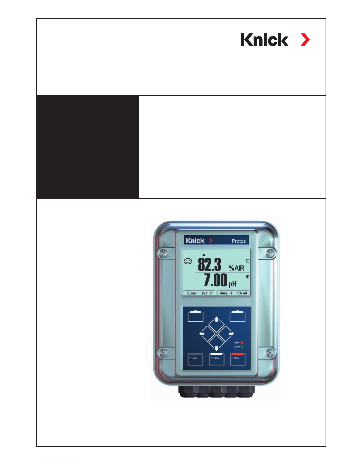
Protos 3400(X)
Process Analysis System
User Manual
System Components FRONT and BASE
Modular measuring system for liquid analysis
with slots for up to 3 measuring and communication
modules
English
Page 2

2
Page 3
Trademarks
The following trademarks are used in this manual without further marking:
are registered trademarks of Knick Elektronische Messgeräte GmbH & Co. KG, Germany
is a registered trademark of
Endress+Hauser Conducta GmbH & Co. KG, Germany
Knick Elektronische Messgeräte GmbH & Co. KG, Germany
is a registered trademark of Toshiba Corp., Japan
Knick
Elektronische Messgeräte GmbH & Co. KG
Beuckestraße 22
14163 Berlin
Phone: +49 (0)30 - 801 91 - 0
Fax: +49 (0)30 - 801 91 - 200
Internet: http://www.knick.de
[email protected]
Warranty
Defects occurring within 3 years from delivery date shall be remedied
free of charge at our plant (carriage and insurance paid by sender).
Sensors, fittings and accessories: 1 year.
©2014 Subject to change without notice
Return of products under warranty
Please contact our Service Team before returning a defective device. Ship the cleaned device to
the address you have been given. If the device has been in contact with process fluids, it must be
decontaminated/ disinfected before shipment. In that case, please attach a corresponding certificate,
for the health and safety of our service personnel.
Disposal
Please observe the applicable local or national regulations concerning the disposal of
“waste electrical and electronic equipment”.
Page 4

4
Table of Contents
Warranty ........................................................................................................................................ 2
Return of Products Under Warranty .................................................................................... 2
Disposal ......................................................................................................................................... 2
Trademarks ................................................................................................................................... 2
EC Declaration of Conformity ......................................................................... 3
Intended Use .................................................................................................... 8
Package Contents ......................................................................................................................9
Safety Information ........................................................................................ 10
Information on Commissioning/Start-up ........................................................................11
Conformity with FDA 21 CFR Part 11 ................................................................................ 12
Product Line ...............................................................................................................................13
Device Software Protos 3400(X): Version 9.x..................................................................16
System Overview .....................................................................................................................17
Modular Concept .....................................................................................................................19
Short Description .......................................................................................... 20
Short Description: FRONT Module ....................................................................................20
Short Description: Menu Structure ....................................................................................21
Short Description: BASE Module ........................................................................................ 23
Connection of Power Supply ........................................................................ 24
1. BASE 3400-021 Module (Non-Ex)...................................................................................25
2. BASE 3400X-025/VPW Module (Ex) ...............................................................................26
3. BASE 3400X-026/24V Module (Ex) .................................................................................27
Hazardous-Area Connection to Protos 3400X ............................................ 28
Hazardous-Area Components (Example) ........................................................................29
Dimesion Drawings ....................................................................................... 30
Wall Mounting, Post/Pipe Mounting .................................................................................31
ZU 0548 Weather Protector ..................................................................................................32
ZU 0545 Panel-Mount Kit ......................................................................................................33
Operation (FRONT Module) .......................................................................... 34
Menu Structure .........................................................................................................................34
Menu Selection .........................................................................................................................35
Mode Indicators in the Display ...........................................................................................36
Page 5

5
Table of Contents
How to Enter Numbers and Text ........................................................................................38
Configuring the Measurement Display ............................................................................39
Softkey Function (Function Control) .................................................................................40
Documenting Parameter Setting .......................................................................................43
ProgaLog 3000 Software (Option) for Configuration and
Documentation ........................................................................................... 45
Parameter Setting: Operating Levels .......................................................... 49
Parameter Setting: Lock Functions ....................................................................................50
Function Control Matrix, Time/Date ..................................................................................51
Point of Measurement, Passcodes, Release of Options ..............................................52
Factory Setting, Logbook ......................................................................................................53
Language, Measurement Display, Viewing Angle ........................................................54
Calculation Blocks (System Control) ..................................................................................55
Calculation of new variables from measured variables ....................................55
Activating Calculation Blocks ......................................................................................56
Overview of Calculation Blocks .................................................................................. 57
Calculation Formulas ......................................................................................................58
Configuring a Calculation Block .................................................................................59
Logbook ......................................................................................................................................60
Factory setting ..........................................................................................................................60
Switching Between Parameter Sets A, B .......................................................................... 61
Configuring a current output ..............................................................................................62
Current Outputs: Characteristics ........................................................................................63
Output Filter ...............................................................................................................................65
NAMUR Signals: Current Outputs ......................................................................................66
NAMUR Signals: Relay Contacts ..........................................................................................67
Relay Contacts: Protective Wiring ......................................................................................68
Relay Contacts, Usage ............................................................................................................69
Relay Contacts: Sensoface Messages ................................................................................70
Rinse Contact .............................................................................................................................71
Icons in the Measurement Display ....................................................................................72
Limit Value, Hysteresis, Contact Type................................................................................72
Page 6

6
OK1, OK2 Inputs: Specify Level ...........................................................................................73
Selecting parameter set (A, B) via OK2 input .................................................................74
Signaling active parameter set via relay contact .........................................................74
Inserting the SmartMedia Card .................................................................... 75
SmartMedia Card: Types ........................................................................................................76
SmartMedia Card: Display Icons .........................................................................................76
Memory Card (SW 3400-102 ... 1xx) ................................................................................... 76
Software Update Card (Additional Function SW 3400-106) .....................................76
SmartMedia Card: Memory Cards ...................................................................................... 77
File Structure of a Memory Card .........................................................................................77
Saving / Loading Device Configuration ...........................................................................78
Transferring the Complete Device Configuration from one Device to
Further Devices .......................................................................................................................78
Using the Memory Card .........................................................................................................79
Formatting the Update Card ................................................................................................80
Removing the Memory card ................................................................................................81
SW 3400-102: Loadable Parameter Sets ..................................................... 82
Parameter set as file on a memory card ..........................................................................82
Saving a parameter set on SmartMedia card ................................................................82
SW 3400-106: Software Update ................................................................... 84
Maintenance .................................................................................................. 87
Diagnostics Functions ................................................................................... 88
Overview .....................................................................................................................................88
Sensoface ....................................................................................................................................89
Activating Diagnostics ...........................................................................................................90
Point of meas description .....................................................................................................90
Logbook .......................................................................................................................................90
SW 3400-104: Extended Logbook ................................................................ 91
Table of Contents
Page 7

7
Table of Contents
Device Description ..................................................................................................................92
FRONT Module ..........................................................................................................................92
BASE Module ..............................................................................................................................92
Message List ..............................................................................................................................95
Messages ........................................................................................................ 96
Specifications ............................................................................................... 118
Glossary ........................................................................................................ 125
Index ............................................................................................................. 134
Menu Structure of Basic Unit ...................................................................... 143
Configuring the System Control .................................................................144
SmartMedia Card Features ......................................................................... 144
Page 8

8
Intended Use
The Protos 3400(X) modular process analysis system is preferably used to measure and process electrochemical quantities in liquids. It has a modular design
and consists of the BASE power supply unit, the FRONT door and different measuring and communication modules.
Protos 3400X is intended for operation in locations subject to explosion hazards
which require equipment of Group II, device category 2(1), gas/dust.
Protos 3400(X) is a flexible measuring system for continuous measurements in
the field of liquid analysis. Thanks to its modular design, it can be easily adapted to your measuring task. Flexible use of plug-in modules allows combined
measurements as well as later expansions or modifications. The measured variables depend on the measuring modules installed. Communication modules
are available for further processing of the output signals. The sturdy enclosure
(IP 65) can be wall or pipe mounted or fixed into a control panel. The version
with hygienic, polished stainless steel enclosure allows application in the field
of biotechnology, food processing, and in the pharmaceutical industry. The
Protos version with coated steel enclosure – extremely corrosion resistant – has
been developed for application in the chemical industry, environmental engineering, water and waste-water treatment, and for application in power plants.
Caution!
Never expose the display to direct sunlight!
At ambient temperatures below 0°C, the legibility of the LC display may be
reduced. This does not impair the device functions.
Page 9

9
Package Contents
• Protos 3400(X) basic unit (FRONT and BASE modules)
• Wall-mount kit
• Test Certificate
• This user manual
• CD-ROM with complete documentation (German, English, French)
- Instruction manuals for all available modules
incl. EC Declarations of Conformity
- Excel files for documenting your individual parameter settings
- Driver files (bus connection)
• For Ex devices (Protos 3400X):
EC-Type-Examination Certificate (ATEX),
FM and CSA incl. Control Drawings
Modules as ordered (each in a separate package with Installation Instructions,
Test Certificate, EC Declaration of Conformity)
Page 10

10
Safety Information
Application in hazardous locations
Protos 3400X modular process analysis system
The Protos 3400X modular process analysis system is intended for operation in
specific environments and specific fields of application. These are listed in the
instruction manual as specifications for environment, installation and commissioning, intended use (= application), assembly and dismantling, and maintenance.
Observe the influences of humidity, ambient temperature, chemicals, and
corrosion. If the specifications in the instruction manual are not sufficient for
assessing the safety of operation, e.g. because your specific applications are not
described, please contact the manufacturer to make sure that the application is
possible and safe.
Prerequisite to safe use of the equipment is the observance of the specified
ambient conditions and temperature ranges.
When using the Protos 3400X modular process analysis system, you must
observe the stipulations for electrical installations in hazardous areas
(EN 60079-14). When installing the device outside the range of applicability
of the 94/9/EC directive, you must observe the appropriate standards and
regulations in the country of use.
The Protos 3400X modular process analysis system has been developed and
manufactured in compliance with the applicable European guidelines and standards. Compliance with the European Harmonized Standards for use in hazardous locations is confirmed by the EC-Type-Examination Certificate. Compliance
with the European guidelines and standards is confirmed by the EC Declaration
of Conformity.
The EC Declaration of Conformity and the EC-Type-Examination Certificate are
included in the instruction manual.
There is no particular direct hazard caused by the operation of the device in the
specified environment.
Page 11
11
Safety Information
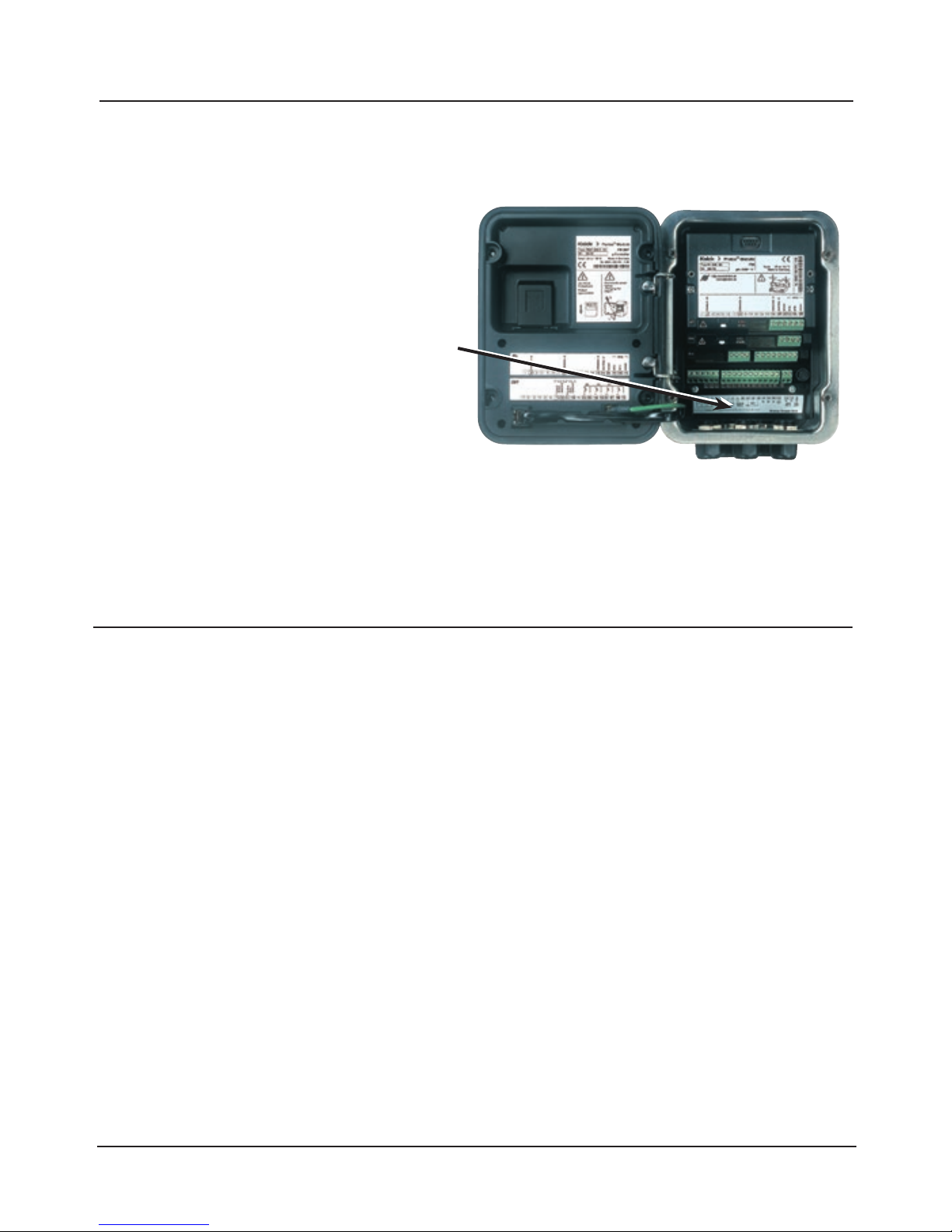
During operation, the Protos 3400X
modular process analysis system
may be opened briefly to replace the
SmartMedia card. The mains terminal
cover must be opened only when the
unit is de-energized.
Installation:
The power supply must be disconnectable near the device by a two-poled
switch incorporated in the building
installation. This switch must meet the
requirements of EN 60947-1 and EN 60947-3, be marked as disconnect device
for Protos 3400(X), and be easily accessible by the user.
Caution!
• Before commissioning it must be proved that the device may be connected
with other equipment.
• Commissioning must only be performed by trained personnel authorized by
the operating company!
• The combination of hazardous-area and safe-area modules
(mixed configuration) is not permitted.
Whenever it is likely that protection has been impaired, the device shall be
made inoperative and secured against unintended operation. The protection is
likely to be impaired if, for example:
• the device shows visible damage
• the device fails to perform the intended measurements
• after prolonged storage at temperatures above 70 °C
• after severe transport stresses
Before recommissioning the device, a professional routine test in accordance
with EN 61010-1 must be performed. This test should be carried out at the
manufacturer's factory.
Information on Commissioning/Start-up
Page 12

12
In their directive “Title 21 Code of Federal Regulations, 21 CFR Part 11,
Electronic Records; Electronic Signatures“ the US American health agency FDA
(Food and Drug Administration) regulates the production and processing of
electronic documents for pharmaceutical development and production. This
results in requirements for measuring devices used for corresponding applications. The following features ensure that the Protos 3400(X) modular process
analysis system meets the demands of FDA 21 CFR Part 11:
Electronic Signature
Access to the device functions is regulated and limited by individually adjustable codes – “Passcodes”. This prevents unauthorized modification of device
settings or manipulation of the measurement results. Appropriate use of these
passcodes makes them suitable as electronic signature.
Audit Trail Log
Every change of device settings can be automatically recorded and documented in the Audit Trail Log on the SmartMedia card. The recording can be
encrypted.
Conformity with FDA 21 CFR Part 11
Page 13

13
Product Line
Standard version
PROTOS 3400 S
PROTOS 3400 C
PH 3400-033
PH 3400-035
COND 3400-041
CONDI 3400-051
OUT 3400-071
COMPA 3400-081
PHU 3400-110
PID 3400-121
CO2 3400-130
Basic unit, stainless steel enclosure
Basic unit, coated steel enclosure
Module: pH (Pfaudler probes)
Module: pH (ISM sensors)
Module: Conductivity
Module: Electrodeless cond.
Module: Output expansion
Module: Profibus PA
Module: UNICAL control module
Module: PID Controller
Module: CO2
3400 S
3400 C
PH 3400-033
PH 3400-035
COND 3400-041
CONDI3400-051
OUT 3400-071
COMPA 3400-081
PHU 3400-110
PID 3400-121
CO2 3400-130
Device (standard version) Order No.
OXY 3400-067 Module: Oxygen (ISM, traces) OXY 3400-067
COMFF 3400-085 Module: Foundation Fieldbus COMFF 3400-085
FIU 3400-141 Module: FIU (Radio, Memosens,
Unical, Uniclean probe controllers)
FIU 3400-141
MS 3400-160 Module: Memosens sensors MS 3400-160
Page 14

14
Device (hazardous-area version)
PROTOS 3400X S/VPW
PROTOS 3400X S/24V
PROTOS 3400X C/VPW
PROTOS 3400X C/24V
PH 3400X-033
PH 3400X-035
COND 3400X-041
CONDI 3400X-051
Basic unit, stainless steel enclosure
withVariPower power supply unit
Basic unit, stainless steel enclosure
with24 V power supply unit
Basic unit, coated stainless steel,
withVariPower power supply unit, AC
Basic unit, standard enclosure
with24V power supply unit, AC/DC
Module: pH (Pfaudler probes)
Module: pH (ISM sensors)
Module: Conductivity
Module: Electrodeless conductivity
Order No.
3400X S/VPW
3400X S/24V
3400X C/VPW
3400X C/24V
PH 3400X-033
PH 3400X-035
COND 3400X-041
CONDI 3400X-051
OUT 3400X-071 Module: Output expansion OUT 3400X-071
COMPA 3400X-081 Module: Profibus PA COMPA 3400X-081
PHU 3400X-110 Module: UNICAL control module PHU 3400X-110
PID 3400X-121 Module: PID controller PID 3400X-121
CO2 3400X-130 Module: CO2 CO2 3400X-130
Product Line
Hazardous-area version
OXY 3400X-067 Module: Oxygen (ISM, traces) OXY 3400X-067
FIU 3400X-140-2 Module: FIU
(Memosens, Unical)
FIU 3400X-140-2
COMFF 3400X-085 Module: Foundation Fieldbus COMFF 3400X-085
Page 15

15
Product Line
Additional functions and accessories
Additional functions Order No.
KI recorder TAN SW 3400-001
Buffer sets to be entered (pH) TAN SW 3400-002
ServiceScope (pH) TAN SW 3400-004
Tolerance band recorder (pH) TAN SW 3400-005
Current characteristic definable TAN SW 3400-006
TC ultrapure water (Cond) TAN SW 3400-008
Concentration determination (Cond) TAN SW 3400-009
Dissolved oxygen measurement
in carbonated beverages
TAN SW 3400-011
ISFET for PH 3400(X)-035 Module TAN SW 3400-012
5 loadable parameter sets SMARTMEDIA/TAN SW 3400-102
Measurement recorder SMARTMEDIA/TAN SW 3400-103
Extended logbook SMARTMEDIA/TAN SW 3400-104
Software update SMARTMEDIA/TAN SW 3400-106
AuditTrail to FDA 21 CFR Part 11 AuditTrail card/TAN SW 3400-107
Accessories Order No.
SmartMedia card ZU 0543
Pipe-mount kit ZU 0544
Panel-mount kit ZU 0545
Wall-mount kit ZU 0546
Weather protector ZU 0548
Input socket for a combination or
glass electrode with DIN plug ZU 0160
SMEK input socket for sensor cable with 1 coax line ZU 0322
SMEK input socket for sensor cable with 2 coax lines ZU 0324
Memosens function for FIU TAN SW 3400-013
2nd channel for FIU 3400(X)-140 TAN SW 3400-014
FIU 3400(X)-140: OXY TAN SW 3400-015
FIU 3400(X)-140: OXY traces TAN SW 3400-016
Page 16
16
Device Software Protos 3400(X):
Version 9.x
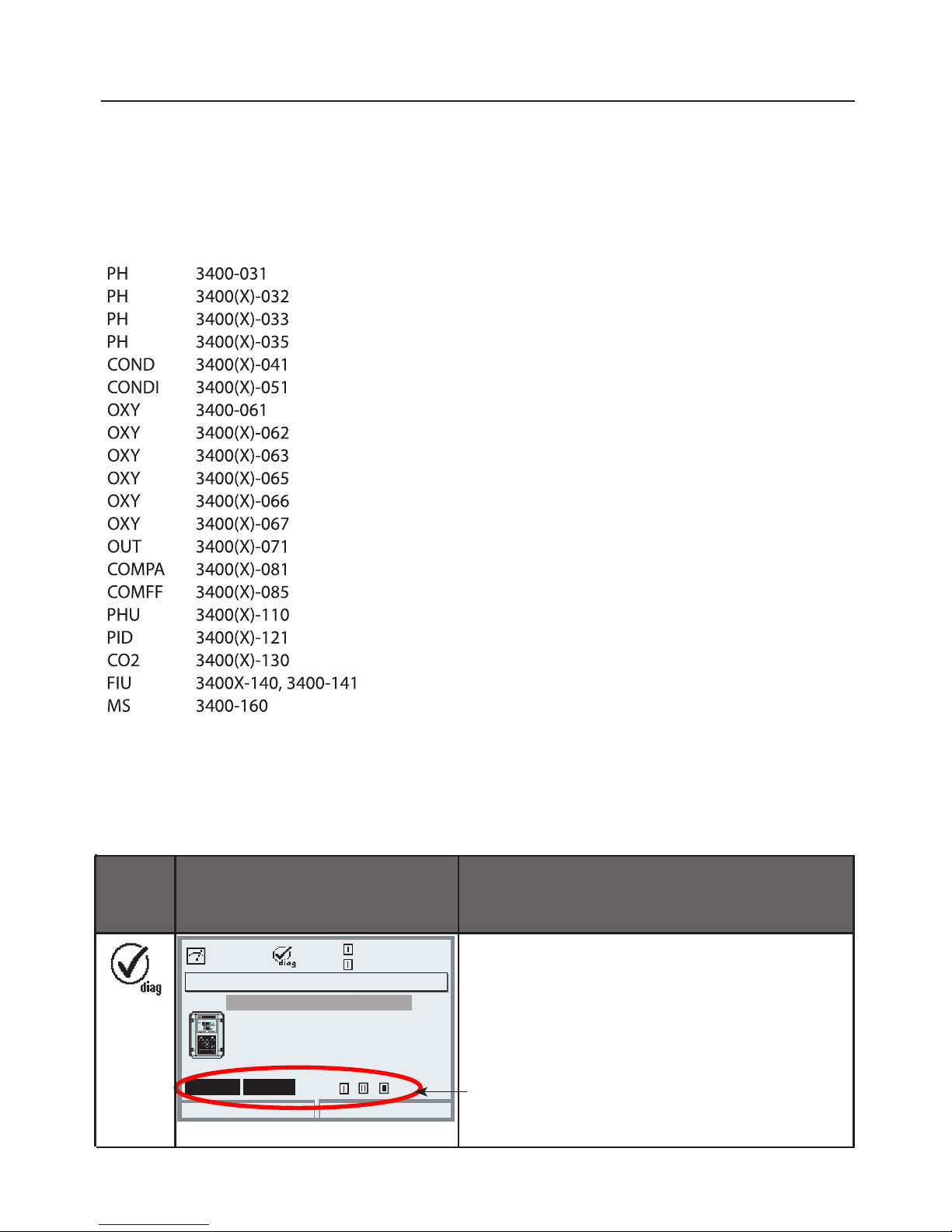
Menu Display Device description
Provides information on all modules
installed: Module type and function,
serial number, hardware and software
version and device options.
Select the different modules (FRONT,
BASE, slots 1 - 3) using the arrow keys.
Device description
Return
22.7 °C
7.00 pH
Operating panel
Module FRONT 3400-011
Hardware: 1 Software: 9.6
Serial number 0000815
BASE
Module
FRONT
Query actual device/module software
When the analyzer is in measuring mode:
Press menu key, open Diagnostics menu.
Options
Modules (For modules which are not listed here, refer to corresponding module manual.)
Module Software version
1.2 - Production stopped
2.0
2.0
3.0
2.0
2.0
1.4 - Module is not supported any more
2.2
2.2
4.0
4.0
3.0
1.1
2.2
1.1
2.1
1.1
1.6
2.0
1.0
Page 17
17
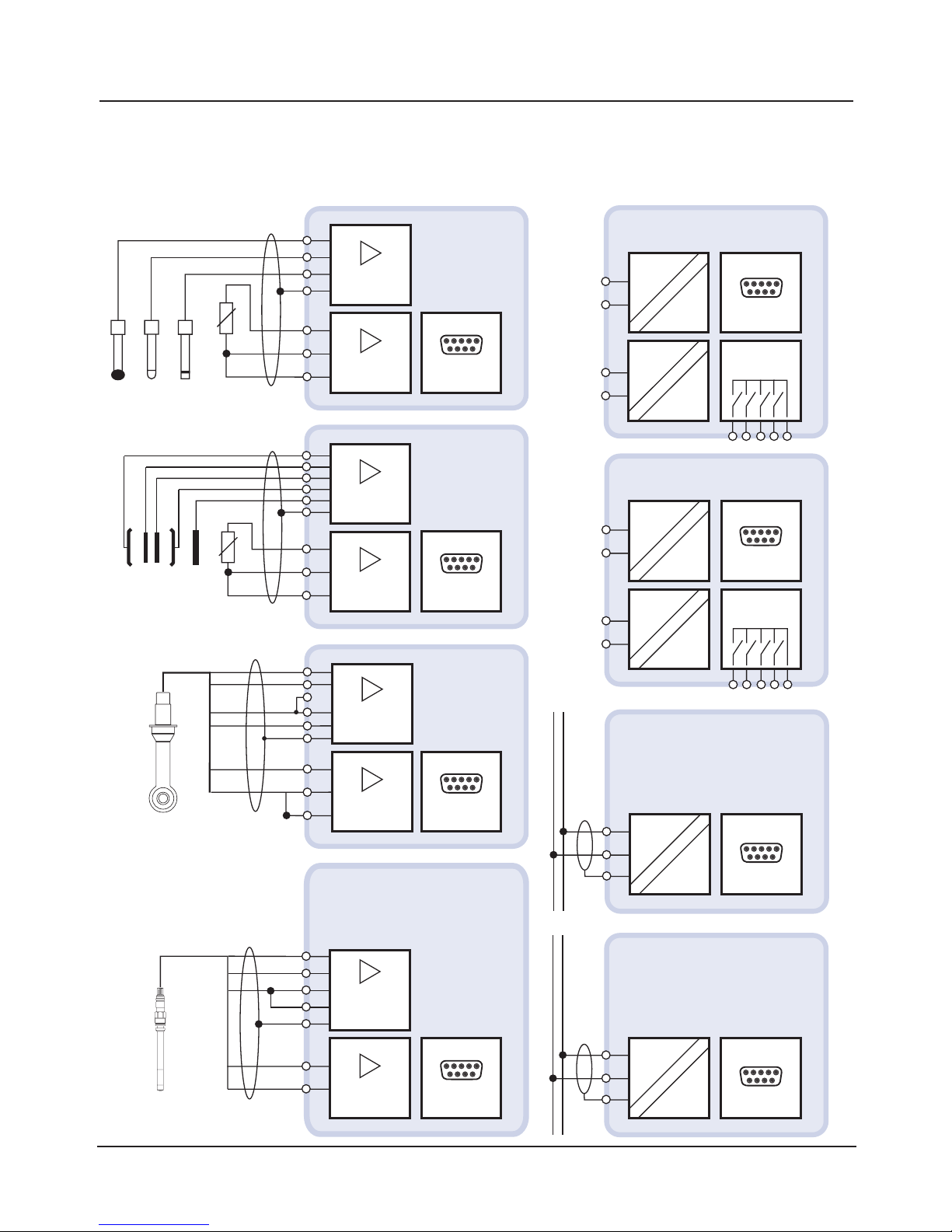
System Overview
Protos 3400(X) modular process analysis system:
Measuring modules and communication modules
Glass
Reference
ORP
pH, ORP
Mohm, kohm
Temp
Interface
RTD
PH module
3400(X)-032
3400(X)-033
3400(X)-035
2 EL / 4 EL
RTD
µS, mS/cm
% by wt
COND module
3400(X)-041
Temp
Interface
CONDI module
3400(X)-051
Electrodeless sensor
µS, mS/cm
% by wt
Temp
Interface
O2 sensor
O2, %
µg/l, ppb
mg/l, ppm
OXY module
3400(X)-062
3400(X)-063
3400(X)-065
3400(X)-066
3400(X)-067
Temp
Interface
OUT module
3400(X)-071
I 3
I 4
mA
Interface
Electronic
contacts
mA
PID module
3400(X)-121
IV 1
IV 2
mA
Interface
Electronic
contacts
mA
Fieldbus
COMFF module
3400 X-085
COMFF
Interface
PROFIBUS-PA
COMPA module
3400 X-081
COMPA
Interface
Page 18
18
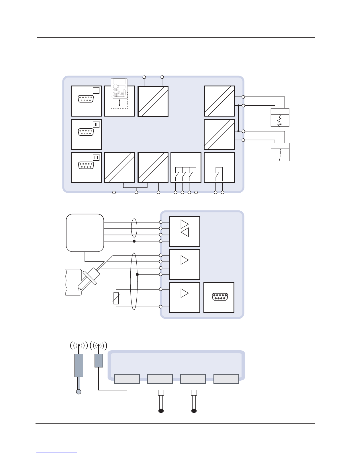
System Overview
Protos 3400(X) modular process analysis system:
Basic unit and controller module for retractable probes
Module
slot
SMARTMEDIA
Protos 3400(X)
OK 1
OK 2
Contacts
K1, K2, K3
Alarm
K4
I 2
mA
I 1
VariPower
0(4) ... 20 mA
pH
Temp
Module
slot
Module
slot
mA
0(4) ... 20 mA
Unical 9000
Uniclean 900
Probe
RTD
Unical/
Uniclean
pH, ORP
MΩ, kΩ
Interface
PHU module
3400(X)-110
Temp
FIU 3400-140 module
ComFu Unical
ComFu E
ComFu C
Sensor and
measuring
module
e.g. SE 533
e.g. SE 533
RS 485
interface
Memosens II Memosens I
Page 19
19
Modular Concept
Basic unit, measuring module, additional functions
Documentation
The basic unit is accompanied by a CD-ROM containing the complete
documentation.
Latest product information as well as user manuals for earlier software
releases are available at
www.knick.de.
The Protos 3400(X) is an expandable modular process analysis system.
The basic unit (FRONT and BASE modules) provides three slots which can be
equipped by the user with any combination of measuring or communication
modules. The software capabilities can be expanded by additional functions
(options). Additional functions must be ordered separately. They are supplied
with a device-specific TAN for function release.
3 module slots
for free combination of
measuring and communication
modules
Measuring modules
• pH / ORP / Temp
• 02 / Temp
• Noncontacting conductivity / Temp
• Contacting conductivity / Temp
• Memosens sensors
Additional functions
Activation via
device-specific TAN
SmartMedia card
Data recording
ProgaLog 3000
Windows® software for
parameter setting and
data evaluation
Protos 3400(X) Modular Process Analysis System
Communication modules
• OUT (additional switching and current
outputs)
• PID (analog and digital controller)
• Profibus PA
• Foundation Fieldbus
• FIU (radio, Memosens, Unical)
(software occupies 2 slots)
• Unical probe controller
Page 20
20
Short Description
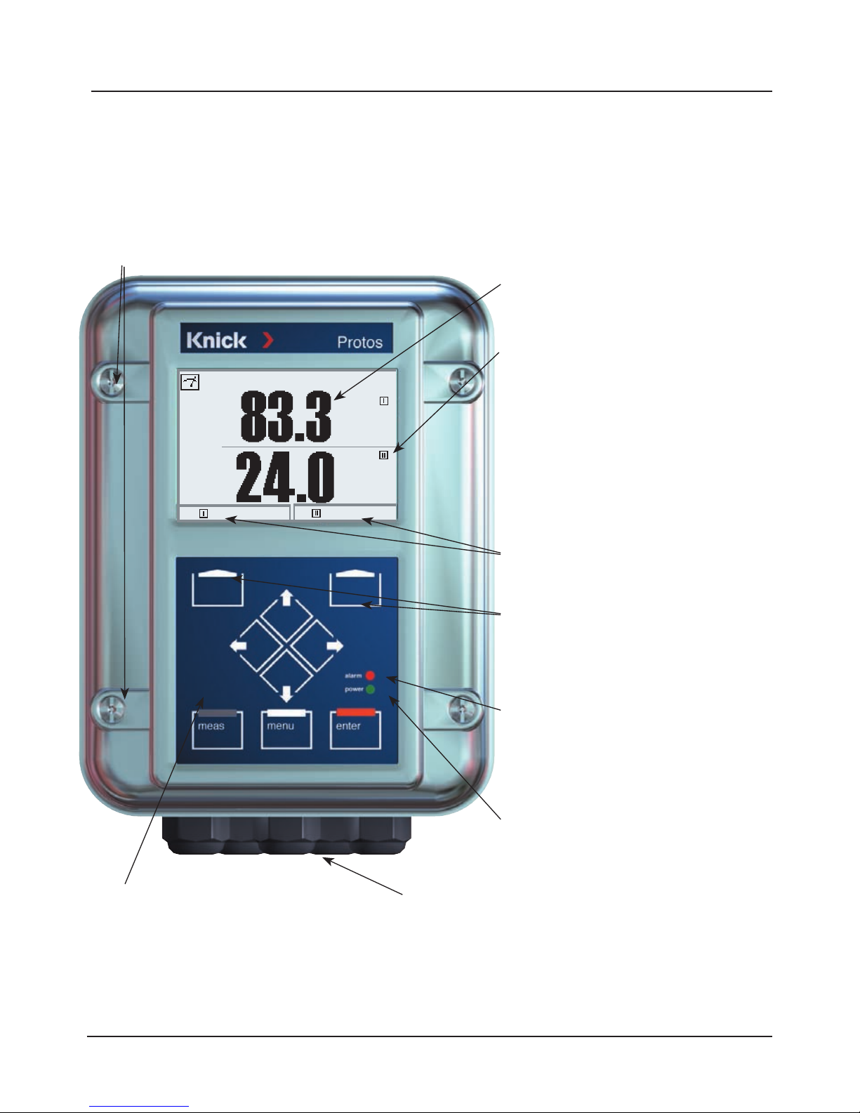
Short description: FRONT module
Transflective LC graphic display
(240 x 160 pixels)
white backlighting, high resolution and
high contrast.
Red LED
signals failure (On) or
maintenance request/function check
(flashing) according to NE 44.
4 captive screws
for opening the analyzer
(Caution! Make sure that the gasket between FRONT and
BASE is properly seated and clean!)
Green LED
Voltage supply okay
5 self-sealing cable glands
M20 x 1.5
for entry of voltage supply and signal lines
2 softkeys
with context-sensitive functions.
User interface
with plaintext menus as recommended by NAMUR.
Menu texts can be switched to:
German, English, French, Italian,
Swedish, and Spanish.
Intuitively acquirable menu logic,
based on Windows standards.
Control panel
3 function keys
(menu, meas, enter)
and 4 arrow keys for menu selection
and data entry
Measurement display
Secondary displays
%Air
°C
24.0°C
25.8°C
Page 21
21
Measure
Short Description: Menu Structure
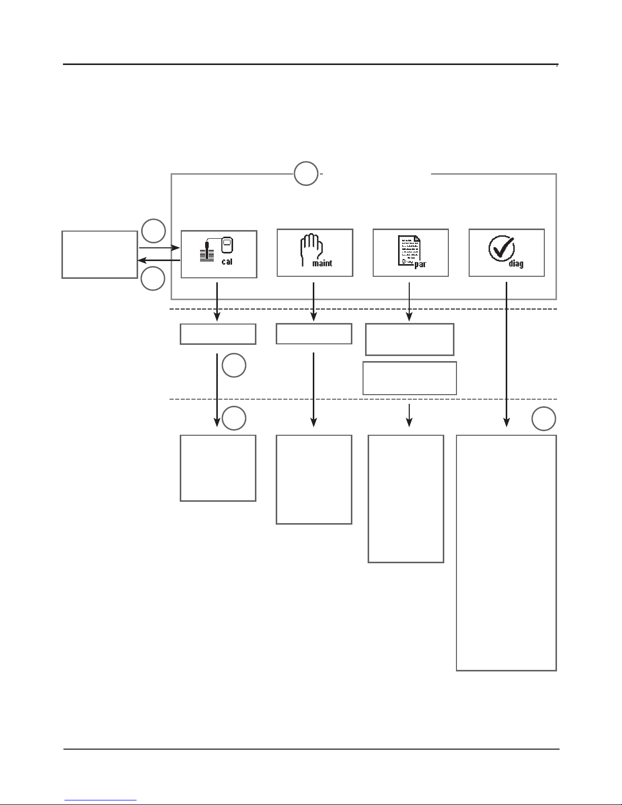
Basic functions: Calibration, Maintenance, Parameter setting, Diagnostics
Calibration
Maintenance
Parameter setting
Diagnostics
Menu groups
1
2
3
1147
2958
1246
Operator level
1989
Administrator level
Passcode:
Selection of
further
menu items:
Module 1
Module 2
Module 3
BASE
Module 1
Module 2
Module 3
SYSTEM
FRONT
BASE
Module 1
Module 2
Module 3
Message list
Point of meas
description
Logbook
Device description
FRONT
BASE
Module 1
Module 2
Module 3
4
5
6
Legend:
1) Pressing the menu key accesses menu selection.
2) Pressing the meas key returns to measurement.
3) Menu groups are selected using the arrow keys
4) Press enter to confirm, enter passcode
5) Further menu items are displayed
6) Selected functions of the Diagnostics menu can be recalled
via softkey even when in measuring mode
Page 22
22
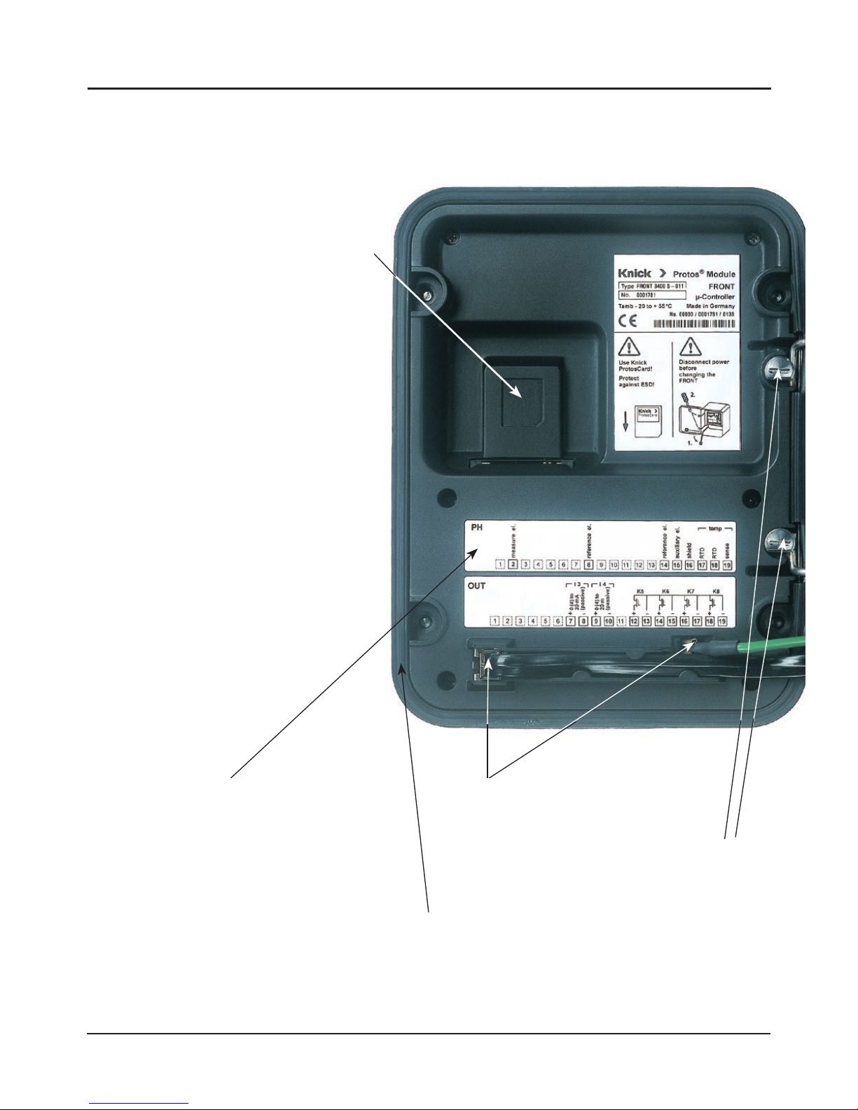
Short Description: FRONT Module
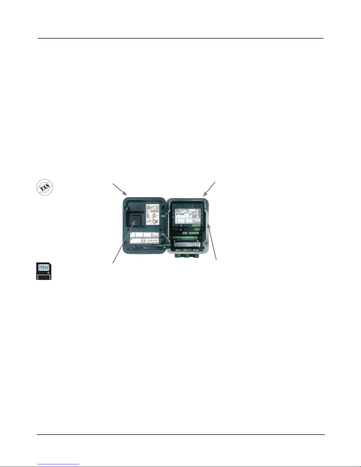
View into the open device (FRONT module)
Terminal plates
of “hidden” modules
Each module comes with an adhesive label
containing the contact assignments. This
label should be sticked to the inner side
of the front (as shown). Then, the terminal
assignments remain visible even if further
modules are inserted.
Slot for SmartMedia card
• Data recording
The SmartMedia card expands the
measurement recorder capacity to
> 50000 records.
• Exchange of parameter sets
5 parameter sets can be stored on the
SmartMedia card, 2 of them can be
loaded simultaneously to the analyzer
and be switched by remote control.
Parameter sets can be transmitted
from one analyzer to the other.
• Function expansions
are possible with additional software
modules, which are released using
transaction numbers (TAN).
• Software updates
The circumferential sealing
guarantees IP 65 protection and allows spray
cleaning / disinfection.
Caution! Keep clean!
Replacing the front module
Pull off power cord and ground wire.
To separate the FRONT module from
the BASE module, turn the retaining screws
of the pivot hinge by 90°.
Page 23
23
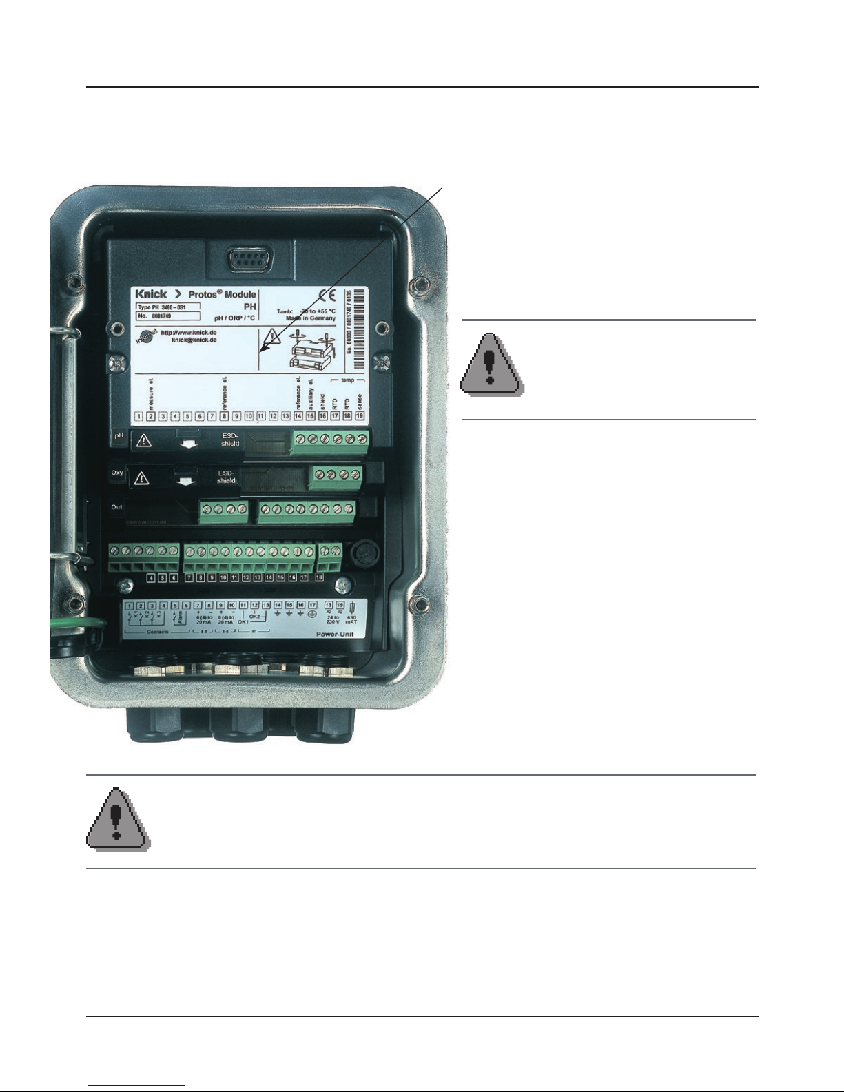
Short Description: BASE Module
View into the open device (BASE module, 3 function modules installed)
BASE module
2 current outputs (free assignment of process variable) and 4 relay contacts,
2 digital inputs.
VariPower broad-range power supply unit,
20 ... 265 V AC/DC, suitable for all public
mains supplies in the world.
Power supply units, Ex version:
100 ... 230 V AC or
24 V AC/DC
Important notice concerning SmartMedia Card
The SmartMedia card may be inserted or replaced with the power supply
switched on. Before a memory card is removed, it must be “closed” in the maintenance menu. When closing the device, make sure that the sealing is properly
seated and clean.
Module equipment
Module identification: Plug & Play.
Up to 3 modules can be combined as
desired. Several input and communication
modules are available.
Warning!
Do not touch the terminal compartment,
there may be dangerous contact voltages!
Notice
Only one module can be
connected in addition to a
FIU 3400(X)-140/141 module.
Page 24
24
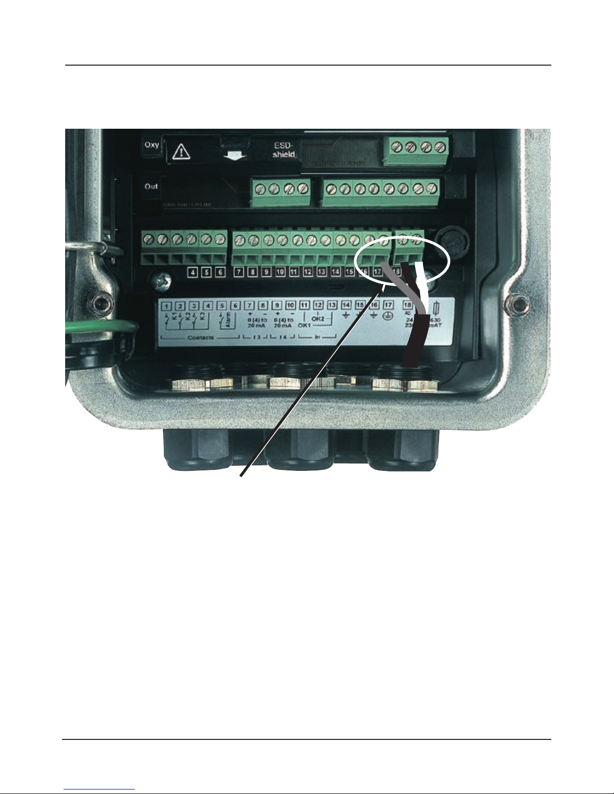
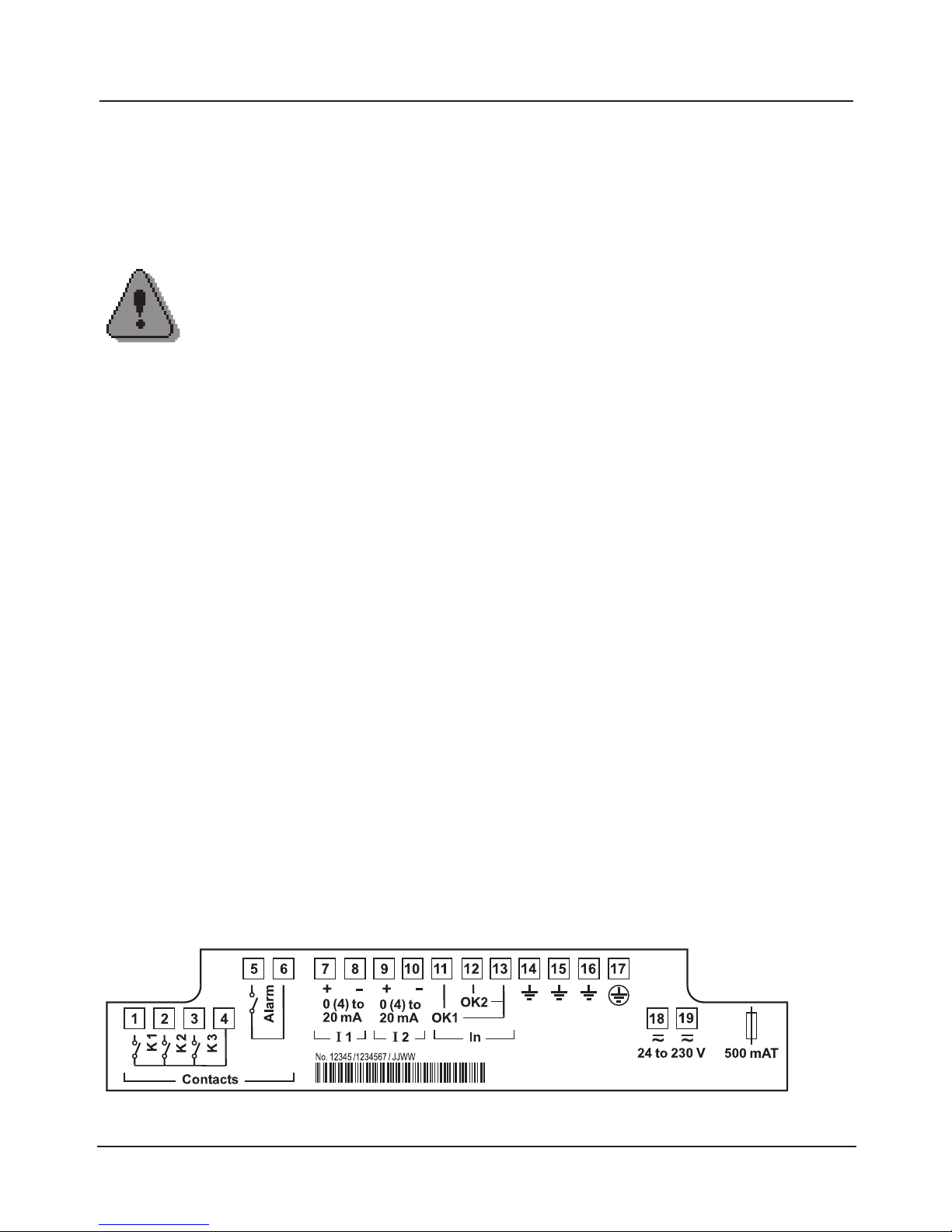
Connection of power supply (BASE 3400-021 module, non-Ex)
The Protos 3400(X) comes in three different versions.
The terminal plates and wirings are shown on the following pages.
1. BASE 3400-021 module (standard version, non-Ex)
VariPower broad-range power supply unit,
24 (-15 %) ... 230 (+15 %) V AC/DC
2. BASE 3400X-025/VPW module (Ex version)
VariPower broad-range power supply unit
3. BASE 3400X-026/24V module (Ex version)
24 V power supply unit
Connection of Power Supply
BASE 3400-021 Module (Non-Ex)
Page 25
25
1. BASE 3400-021 Module (Non-Ex)
Standard version. Not suitable for hazardous-area applications!
Installation instructions
Terminal plate BASE 3400-021 module
Standard version. Not suitable for hazardous-area applications!
Connection of power supply. Contact assignment of inputs/outputs.
Connection of power supply
With the VariPower broad-range power supply unit, the analyzer can be
operated with a power supply of 24 (-15 %) to 230 (+15 %) V AC/DC
making it suitable for all public mains supplies in the world.
The terminals are suitable for single wires and flexible leads up to 2.5 mm
2
(AWG 14).
Caution!
• Installation may only be carried out by trained and qualified
personnel in accordance with the instruction manual and as per
applicable standards and regulations.
• Be sure to observe the technical specifications and input ratings
during installation.
• Be sure not to notch the conductor when stripping the
insulation.
• All parameters must be set by a system administrator prior to
commissioning.
Page 26
26
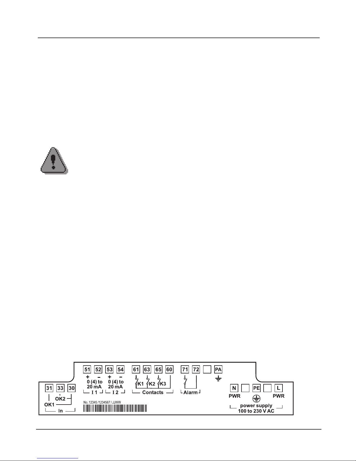
2. BASE 3400X-025/VPW Module (Ex)
Ex version with VariPower power supply unit
Terminal plate BASE 3400X-025/VPW module
(Ex version with VariPower power supply unit)
Connection of power supply. Contact assignment of inputs/outputs.
Installation instructions
When using the Protos 3400X modular process analysis system, the stipulations
for electrical installations in hazardous areas (EN 60079-14) must be observed.
When installing the device outside the range of applicability of the 94/9/EC
directive, the appropriate standards and regulations in the country of use must
be observed.
Caution!
• Installation may only be carried out by trained and qualified
personnel in accordance with the instruction manual and as per
applicable standards and regulations.
• Be sure to observe the technical specifications and input ratings
during installation.
• Be sure not to notch the conductor when stripping the
insulation.
• All parameters must be set by a system administrator prior to
commissioning.
Connection of power supply
With the VariPower broad-range power supply unit, the analyzer can be
operated with a power supply of 100 to 230 V AC (-15 %, +10 %)
(EEx em IIC).
The terminals are suitable for single wires and flexible leads up to 2.5 mm
2
(AWG 14).
Page 27
27
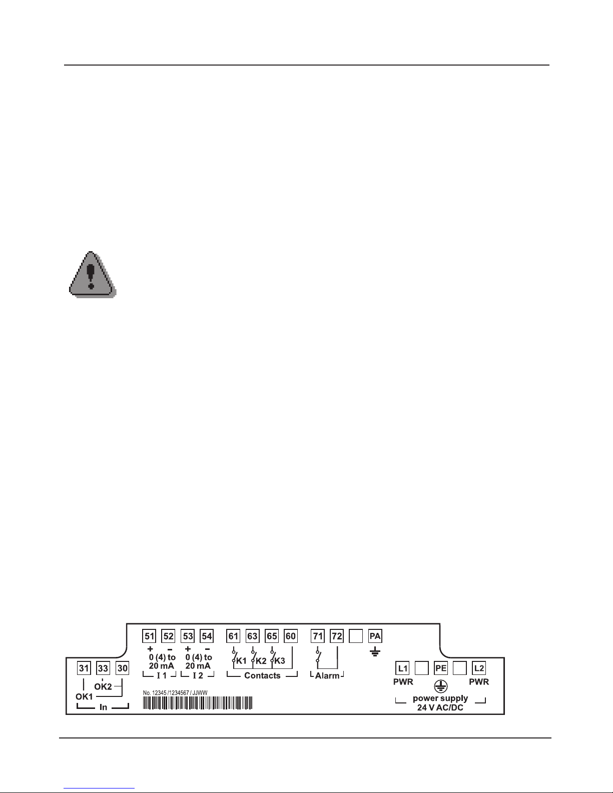
3. BASE 3400X-026/24V Module (Ex)
Ex version with 24 V power supply unit
Terminal plate BASE 3400X-026/24V module
(Ex version with 24 V power supply unit)
Connection of power supply. Contact assignment of inputs/outputs.
Caution!
• Installation of the analyzer may only be carried out by trained
experts in accordance with this instruction manual and as per
applicable local and national codes.
• Be sure to observe the technical specifications and input ratings
during installation.
• Be sure not to notch the conductor when stripping the insulation.
• All parameters must be set by a system administrator prior to
commissioning.
Installation instructions
When using the Protos 3400X modular process analysis system, the stipulations
for electrical installations in hazardous areas (EN 60079-14) must be observed.
When installing the device outside the range of applicability of the 94/9/EC
directive, the appropriate standards and regulations in the country of use must
be observed.
Connection of power supply
With the power supply unit, the analyzer can be operated with a power supply
of 24 V AC (-15 %, +10%) or 24 V DC (-15 %, +20%).
The terminals are suitable for single wires and flexible leads up to 2.5 mm
2
(AWG 14).
Page 28
28
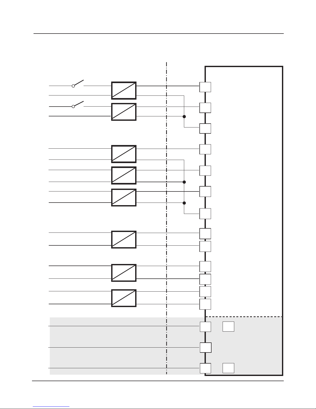
Hazardous-Area Connection to
Protos 3400X
Protos 3400X
OK2
OK1
OK1 ... OK2
K1
K2
K3
K1 ... K3
K4 (Alarm)
Safe area
Hazardous
area
A
A
B
B
B
B
I1
I2
Ex "e”
33
31
30
61
63
65
60
71
72
51
52
53
54
PE
L1
L2
C
C
N
L
0/4 ... 20 mA
0/4 ... 20 mA
Logic input
24 V
GND
24 V
GND
Mains connection: laid in Ex ”e”
Ex "i”
Logic input
Page 29
29
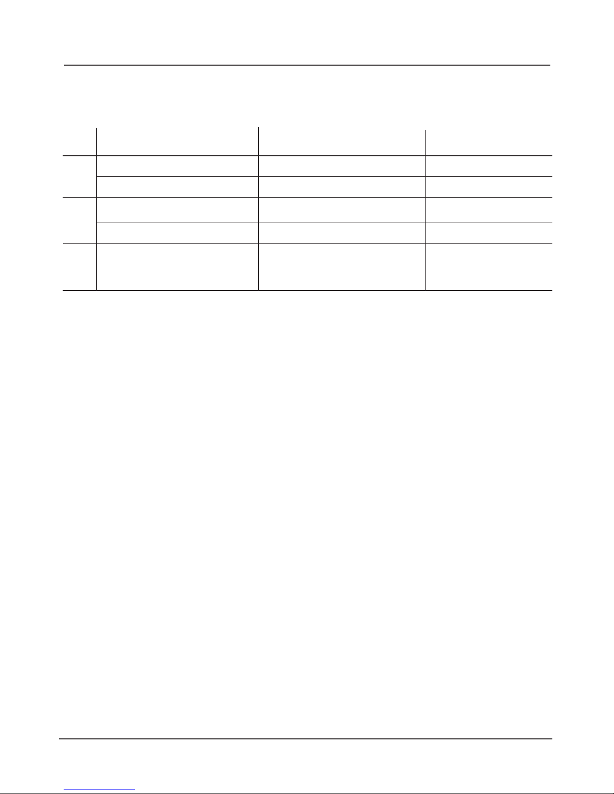
Hazardous-Area Components (Example)
Designation Model Manufacturer
Valve control module KFD2-SL-Ex 1.48**** Pepperl + FuchsA
Valve control module MK 72-S17-Ex0/24VDC TURCK
Switch amplifier KF**-SR2-Ex1.W.** Pepperl + Fuchs
B
Switch amplifier MK1-22Ex0-R/** TURCK
Loop-powered Isolators IsoTrans® 36A7 KnickC
Page 30
30
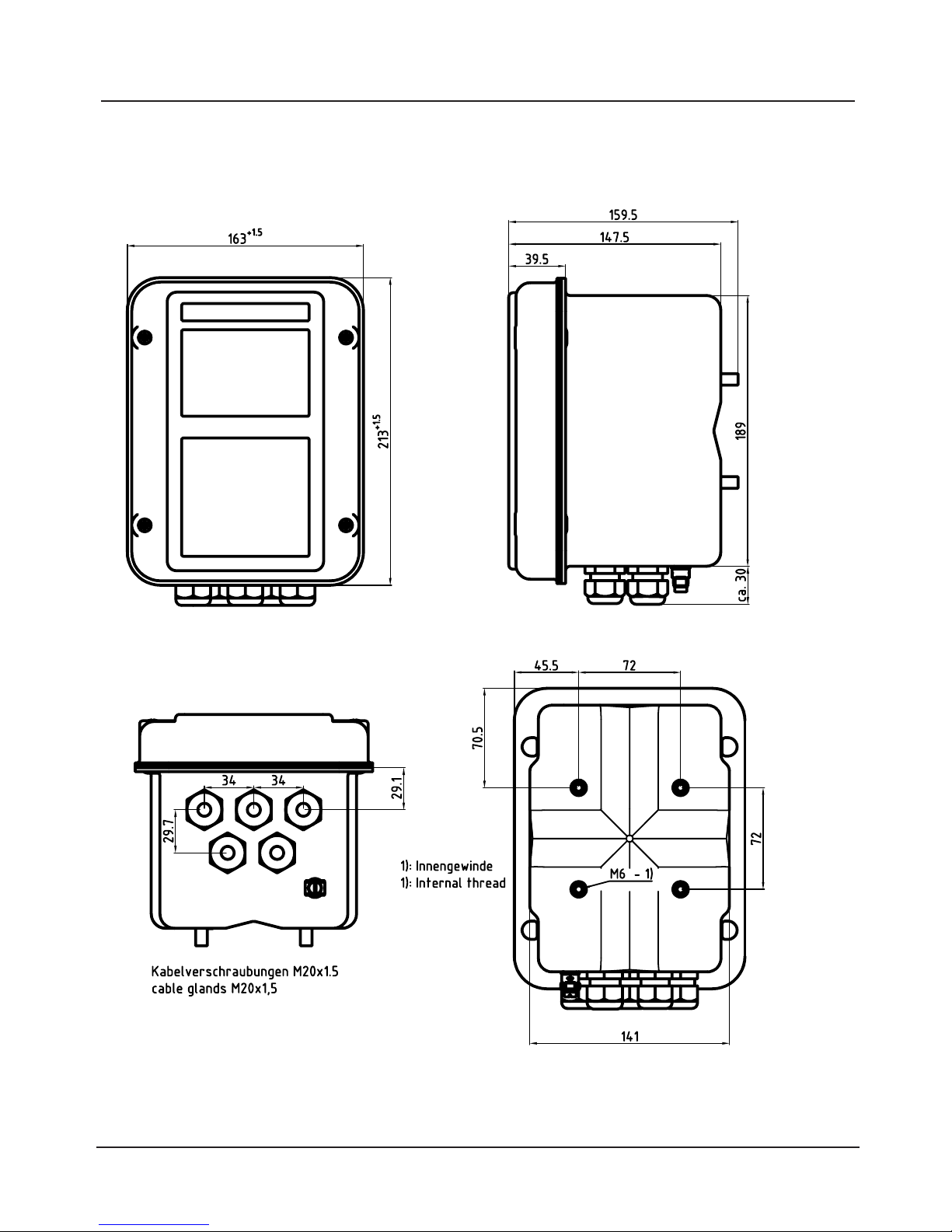
Dimension Drawings
Rear view
Front view
Side view
Dimensions in mm
Page 31
31
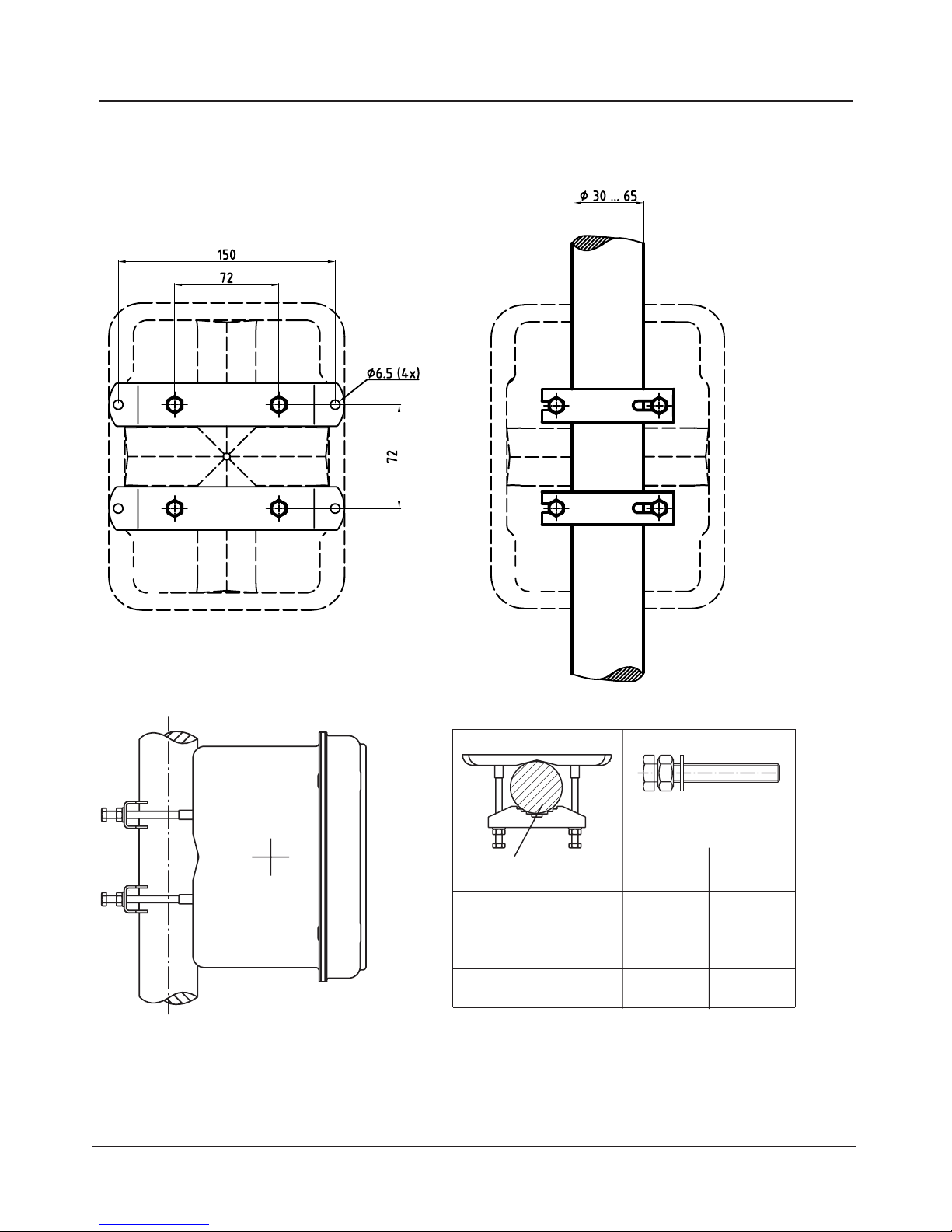
Wall Mounting, Post/Pipe Mounting
Dimension drawings
ZU 0546 wall-mount kit
Post/pipe mounting
ZU 0544 pipe-mount kit
Ø 30 ... 40 mm
Ø 30 ... 65 mm
Ø 40 ... 62 mm
Ø 62 ... 65 mm
X
M6x50
X
X
without nut
M6x70
Ø 30 ... 65 mm
for vertical or horizontal mounting
Dimensions in mm
Page 32
32
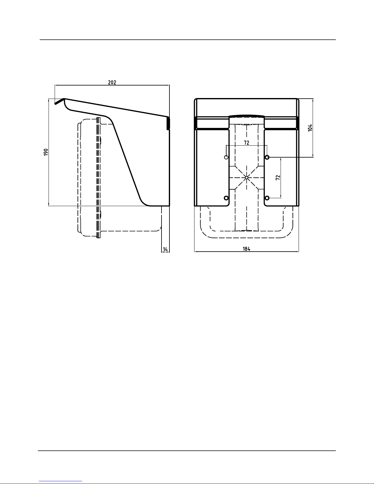
ZU 0548 Weather Protector
Dimension drawings
Page 33
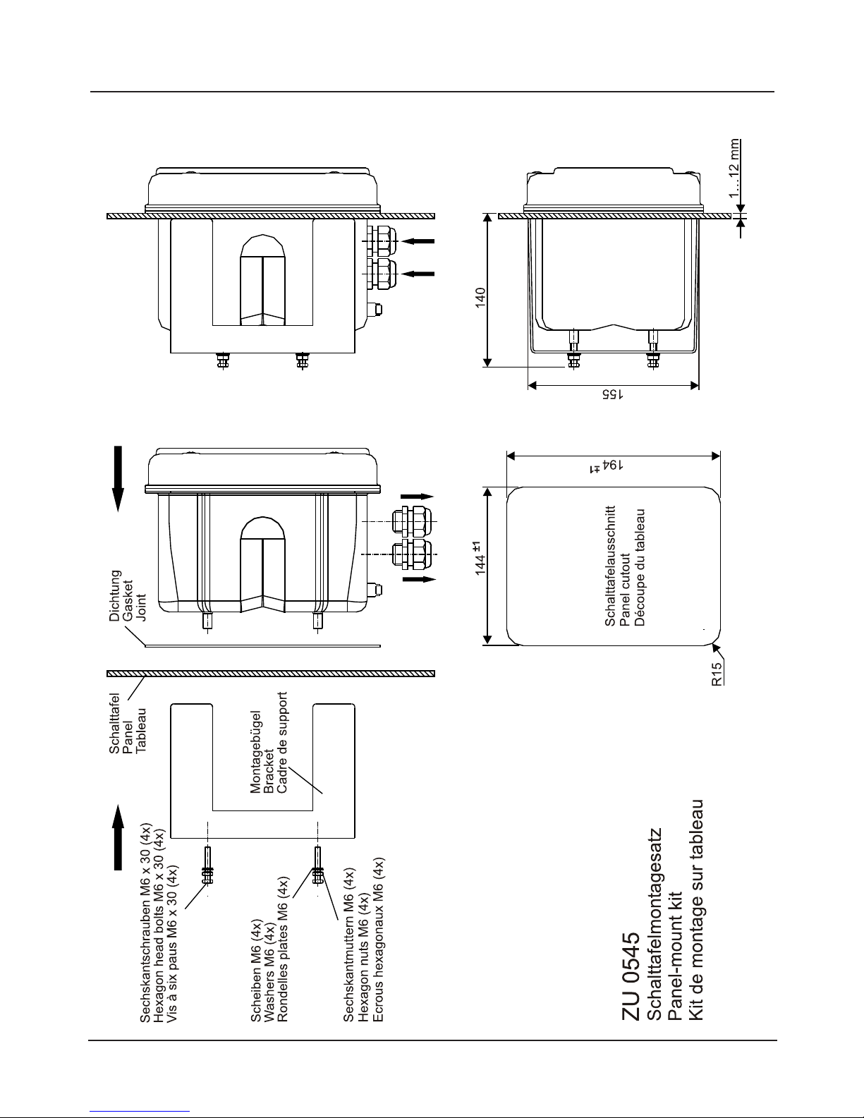
33
ZU 0545 Panel-Mount Kit
Dimension drawings
Page 34
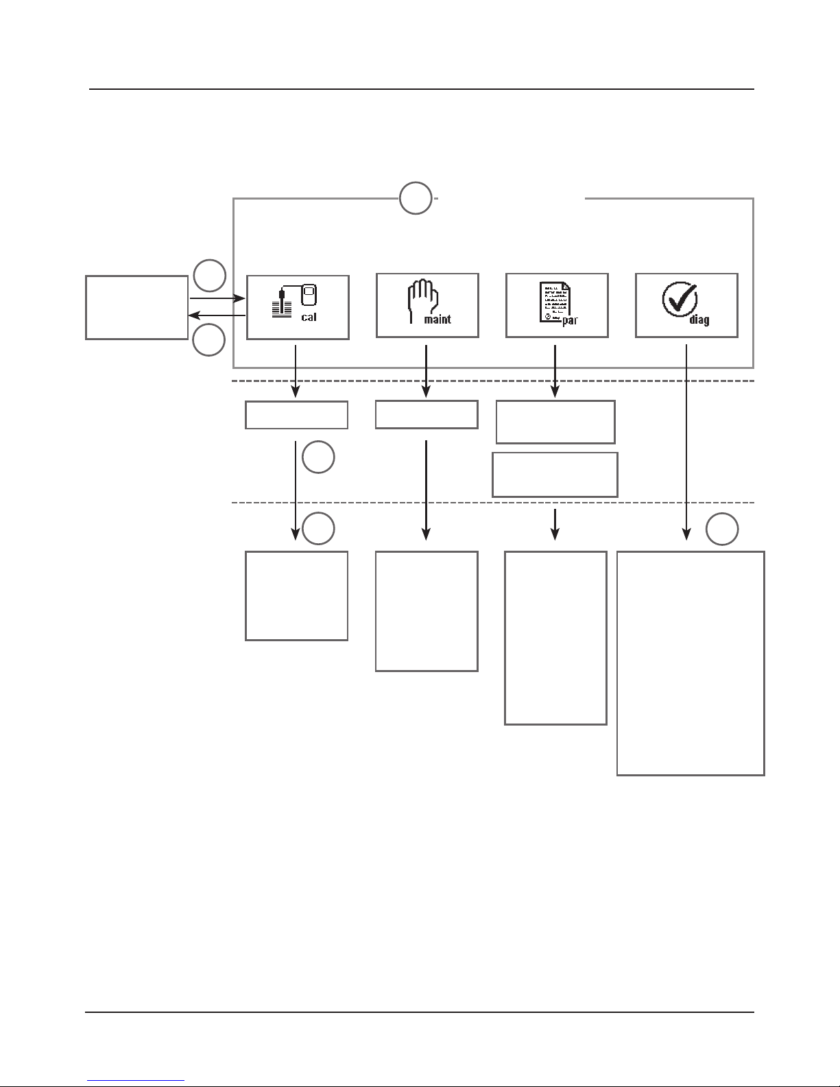
34
Measure
Operation (FRONT Module)
Menu structure
Calibration
Maintenance
Parameter setting
Diagnostics
Menu groups
1
2
3
1147
2958
1246
Operator level
1989
Administrator level
Passcode:
(here:
factory setting)
Selection of
further
menu items:
Module 1
Module 2
Module 3
BASE
Module 1
Module 2
Module 3
SYSTEM
FRONT
BASE
Module 1
Module 2
Module 3
Message list
Point of meas
description
Logbook
Device description
FRONT
BASE
Module 1
Module 2
Module 3
4
5
6
Legend:
1) Pressing the menu key accesses menu selection.
2) Pressing the meas key returns to measurement.
3) Menu groups are selected using the arrow keys
4) Press enter to confirm, enter passcode
5) Further menu items are displayed
6) Selected functions of the Diagnostics menu can be recalled via softkey even
when in measuring mode (Pg 39)
Page 35
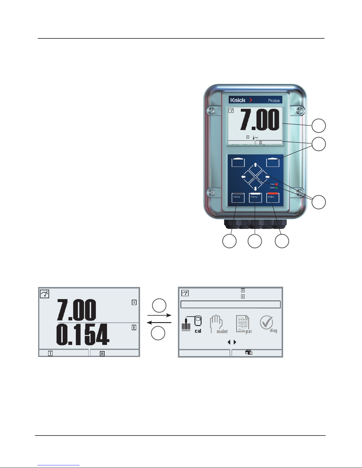
35
1
2
7
8
3
4
1
2
Select the desired menu group using the arrow keys (3).
Press enter (4) to confirm your choice.
An overview of the menu structure is given on Pg 34.
Menu selection
1) Pressing the menu key accesses menu selection.
2) Pressing the meas key returns to measurement.
Menu selection
Return to meas
7.00 pH
25.6°C
Select:
[enter]
Lingua
Menu Selection
FRONT module
After switching on, the analyzer first performs an internal test routine and automatically detects the number and type of
modules installed. Then, the analyzer goes to
measuring mode (Pg 39).
pH
mS/cm
24.3°C
1014 mbars
(Measuring mode)
(Menu selection)
• Configure measurement display (7)
Pg 40
• Secondary displays/softkeys (8)
Pg 41
pH
25.6 °C
02.04.07
Page 36
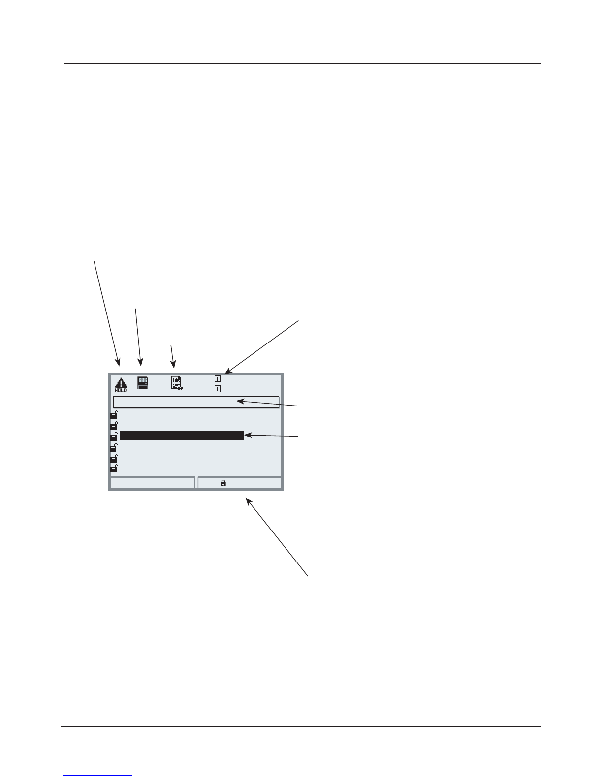
36
Mode Indicators in the Display
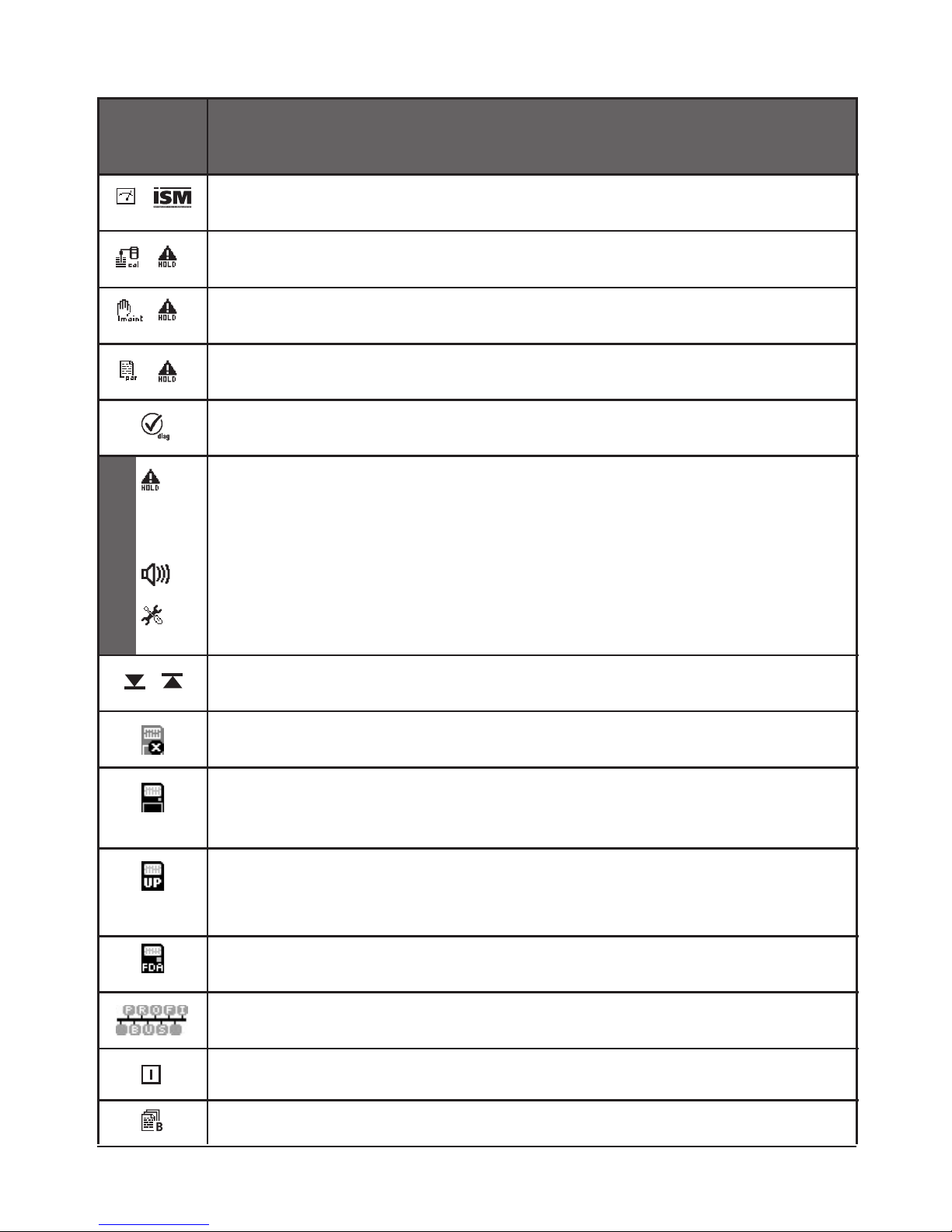
Icons
The plain-text user interface is supplemented by icons which provide
information on the operating status:
Module identification
In the submenus the currently measured values
of the respective module are displayed here.
(number of module slot, no module designation)
Module BASE (Administrator)
Output current I1
Return
Block
0.120 mS/cm
Contact K4
Output current I2
Contact K3
19.0 °C
(NAMUR Failure)
Contact K2
Contact K1
(NAMUR maintenance)
(NAMUR HOLD)
(Limit)
HOLD
The NAMUR "HOLD" mode is active (NAMUR "HOLD" contact (function check));
as delivered, that is the K2 contact of the BASE module (normally open contact).
This setting can be changed as required - the contacts K2 ... K3 are for free programming.
The current outputs behave as configured (you can adjust: last usable value, fixed, 22 mA).
SmartMedia card
located in FRONT module
Mode indication
Parameter setting
Menu level (Administrator level)
Safety of operation
To ensure increased safety of operation, the
device provides three operating levels:
• Administrator level
Access to all device parameters.
Settings can be blocked against access from
the Operator level.
• Operator level
Access to all functions which have been
released at the Administrator level. Blocked
functions are displayed in gray and cannot be
edited.
• Viewing level
Display of all settings.
No editing possible.
Current selection
The current selection is displayed in reverse
video. Gray display lines cannot be edited.
Page 37
37
NAMUR signals
The analyzer is in measuring mode, an ISM sensor is connected.
The device is in calibration mode. HOLD mode is active.
The device is in maintenance mode. HOLD mode is active.
The device is in parameter setting mode. HOLD mode is active.
The device is in diagnostics mode.
HOLD. The NAMUR “HOLD” contact is active (factory setting: Module BASE, Contact K2,
N/O contact). Current outputs as configured:
• Current meas.: The currently measured value appears at the current output
• Last usable value: The last measured value is held at the current output
• Fixed 22 mA: The output current is at 22 mA
The analyzer contains an enabled SmartMedia "memory card". During data recording the
dot in the icon flashes. Please note:
"Close memory card" in the maintenance menu before removing the SmartMedia card.
Limit indication: Lower / upper range limit exceeded
The analyzer contains a SmartMedia card of the type "memory card to FDA 21 CFR Part 11".
Serves for consistent recording of all operations (SW 3400-107).
Displayed in plain text, when the analyzer is controlled via PROFIBUS PA.
Only in conjunction with a BUS module. Different representation for Foundation Fieldbus.
Designates the module slot (1, 2 or 3), allowing the clear assignment of measured-value/
parameter displays in the case of identical module types.
Indicates the active parameter set. (The analyzer provides two parameter sets A and B.
Up to 5 sets can be added using additional functions and SmartMedia card.)
Failure: The NAMUR “failure” contact is active (factory setting: Module BASE, Contact K4,
N/C contact). To view error message, call: Diagnostics menu/Message list
Maintenance: The NAMUR “maintenance request” contact is active (factory setting: Module
BASE, Contact K2, N/O contact). To view error message, select: Diagnostics menu/Message
list
The analyzer contains a SmartMedia "update card". You can save the current device software
or perform a software update from the SmartMedia card. Be sure to check the configuration
after the update is completed.
The analyzer contains a SmartMedia "memory card". The card is closed and can be removed
or enabled in the maintenance menu.
Display
Explanation of display icons
Page 38
38
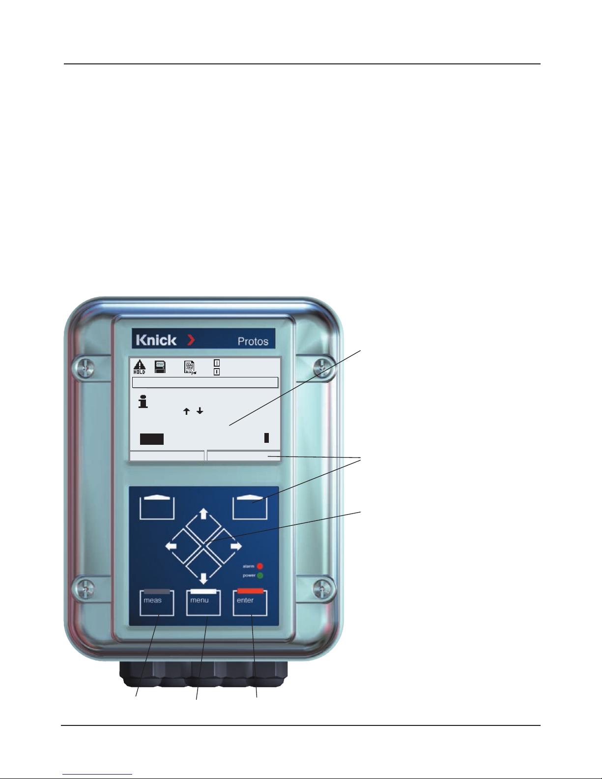
Select the position using the left/right keys,
then edit the number or letter using the up/down keys.
Confirm with enter.
Example: Entering a tag number (point of measurement)
• Open the menu selection (menu)
• Select parameter setting
• Administrator level, enter passcode
• Select point of measurement:
Point of measurement
You can enter a tag number for
the measurement point and notes
using the arrow keys.
Arrow keys
For selection of menu lines or
entry of letters and numbers.
enter
Function
which is assigned to the softkey
underneath.
Point of measurement
Enter 0...9A...Z-+/
Abort
OK
using
Meas.point
M402.......................M402.......................
Note
REV-020407.
meas menu
25.6 °C
0.120 mS/cm
How to Enter Numbers and Text
FRONT Module
Page 39
39
Configuring the Measurement Display
FRONT module
Select menu: Parameter setting/Module FRONT/Measurement display
Pressing meas returns the analyzer to the measuring mode from any function.
(Pressing meas in measuring mode, successively displays the activated special
functions such as measurement recorder or KI recorder).
All process variables coming from the modules can be displayed. The table on
the next page describes how to configure the measurement display.
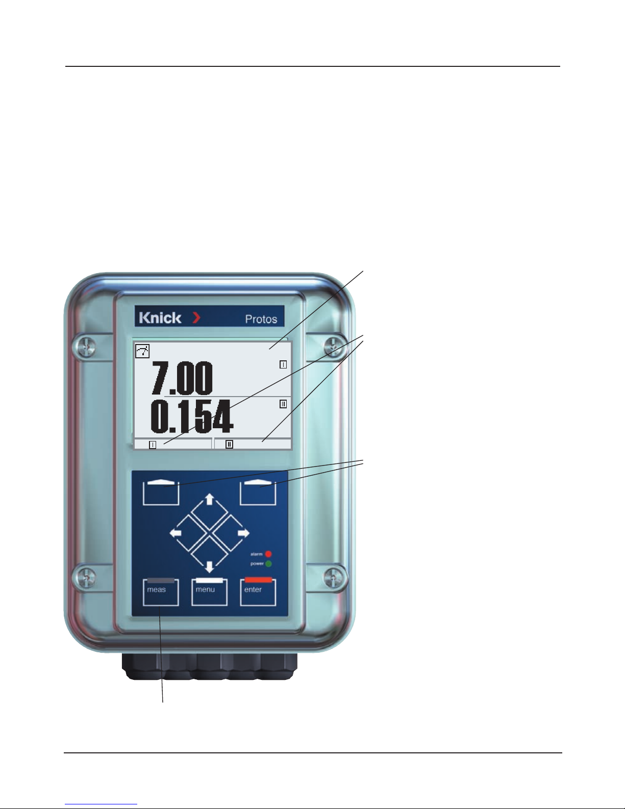
Secondary displays
Additional values, also date and time,
can be displayed depending on the
modules installed. They are selected
using the softkeys (Pg 41).
Measurement display
Typical measurement display
(pH, COND modules)
pH
mS/cm
24.3°C
02.04.07
Softkeys
The softkeys allow selection of
values for the secondary displays.
In addition, Diagnostics functions
which are set as “Favorites” can be
called (Pg 42).
If required, you can also change the
parameter set via softkey (Pg 42)
Furthermore, the softkeys include
- self-explaining - context-sensitive
functions, e.g. with measurement or
KI recorder activated.
meas
Page 40
40
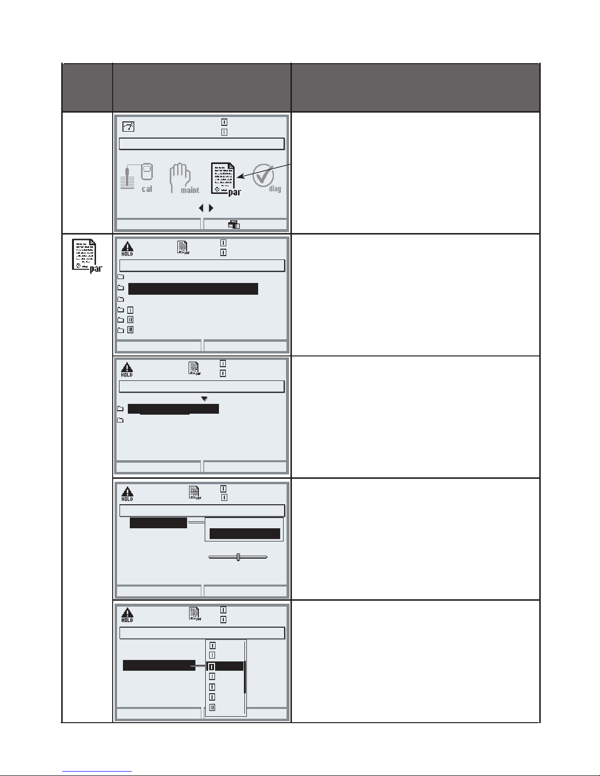
Menu Display Configure measurement display
Configure measurement display
Press menu key to Menu selection
Select parameter setting using arrow
keys, confirm with enter. Select:
“Administrator level”: Passcode 1989
Parameter setting:
Select “Module FRONT”
Front module:
Select “Measurement display”
Measurement display:
Set the number of primary values (large
display) to be displayed
Select process variable(s) to be displayed and confirm with enter.
Pressing the meas key returns to measurement.
Menu selection
Return to meas
7.00 pH
25.6 °C
Select:
[enter]
Lingua
System control
Return
25.6 °C
Module BASE 3400-021
Module PH 3400-032
7.00 pH
Module COND 3400-041
Module COND 3400-041
Languages
Return
25.6 °C
Measurement recorder
7.00 pH
English
Measurement display
Module FRONT 3400-011
25.6 °C
7.00 pH
1 primary value
1st primary value
Viewing angle
2 primary values
Abort
OK
25.6 °C
7.00 pH
1st primary value
Viewing angle
Main display
Abort
OK
Main display
mg/l
%Air
%O2
mg/l
ppm
mbar
pH
values
2nd primary value
°C
Measurement display (Administrator)
2nd primary value
Parameter setting (Administrator)
Module FRONT (Administrator)
Measurement display (Administrator)
Page 41
41
Softkey Function (Function Control)
FRONT Module
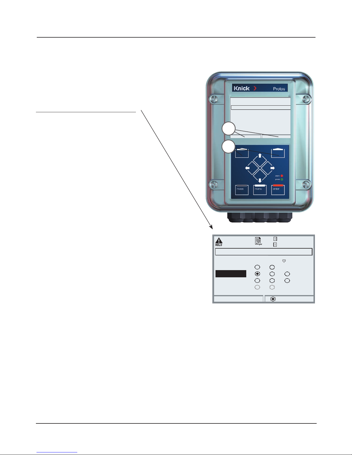
Select menu: Parameter setting/System control/Function control matrix
Favorites Menu
Selected Diagnostics functions can be
called directly from the measuring mode
using a softkey. The following table (Pg 42)
explains how to select favorites.
In measuring mode you can use the
softkeys (1) to control functions.
The functions are assigned in the
function control matrix (Fig.)
(Parameter setting/System control).
Softkeys which have not been assigned to a
certain function are automatically used for
selecting the secondary displays.
Secondary Display (2)
Here, additional values are displayed in
the measuring mode. They are selected
by pressing the respective softkey.
Always active.
You can choose one of the process variables
supplied by the modules (and Calculation
Blocks) or the date or time.
Further functions which can be controlled
via softkey:
• Parameter set
• KI recorder start/stop
• Unical probe controller
Example:
“Parameter set” to be selected with “Left
softkey”.
To select a softkey function:
Select the control element (“Left softkey”), then the “ParSet” function.
Then press “Connect” softkey and
confirm with enter.
To deselect a function:
Press “Disconnect” softkey,
confirm with enter.
2
1
25.6 °C
Input OK2
7.00 pH
Return
Connect
Function control matrix (Administrator)
Left softkey
Right softkey
Profibus DO 2
ParSet KI rec. Fav Unical
– –
–
–
––
Page 42
42
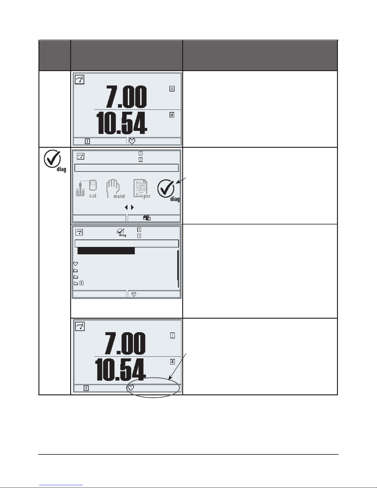
Notice:
When one of the softkeys has been assigned to the “Favorites menu” function,
diagnostic functions which have been set as “Favorite” can be directly called
from the measuring mode.
Menu Display Select favorites
Favorites menu
Diagnostics functions can be called
directly from the measuring mode
using a softkey.
The “Favorites” are selected in the
Diagnostics menu.
Select favorites
Press menu key to select menu.
Select diagnostics using arrow keys,
confirm with enter.
Set/delete favorite:
“Set favorite” allows activation of the
selected diagnostic function directly
from the measuring mode via softkey.
The respective function is marked with
a heart icon.
(See Softkey Function, Pg 41).
Pressing the meas key returns to measurement. When the softkey has been
assigned to “Favorites”, “Favorites menu”
is read in the secondary display
(See Softkey Function, Pg 41).
pH
pH
24.3°C
Favorites menu
pH
pH
24.3°C
Favorites menu
Menu selection
Return to meas
7.00 pH
24.3°C
Select:
[enter]
Lingua
Return
24.3°C
Set favorite
7.00 pH
Logbook
Message list
Device description
Module FRONT 3400-011
Module PH 3400-032
Module BASE 3400-021
Diagnostics
Page 43
43
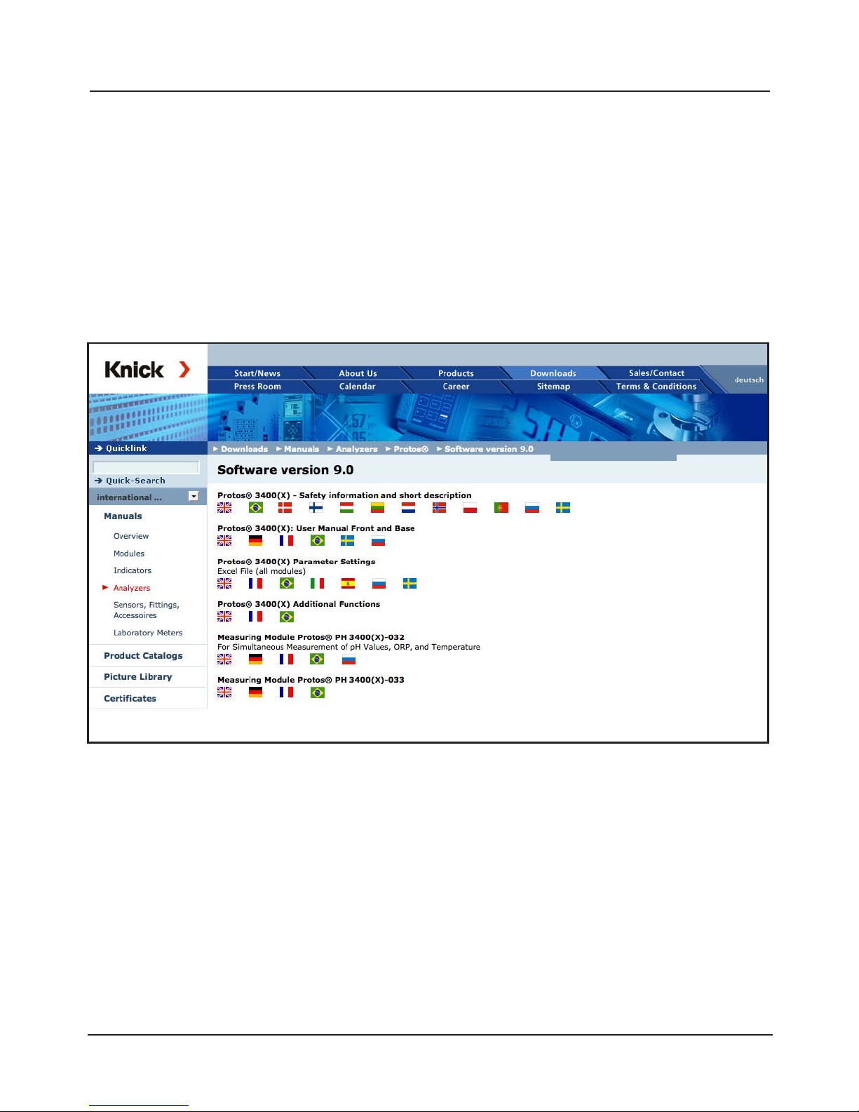
You must reproducibly document all parameter settings in the device to
achieve a high level of system and device security according to GLP. For that
purpose, an Excel file is provided (on the CD-ROM shipped with the basic
device or as download at www.knick.de) to enter the parameter settings.
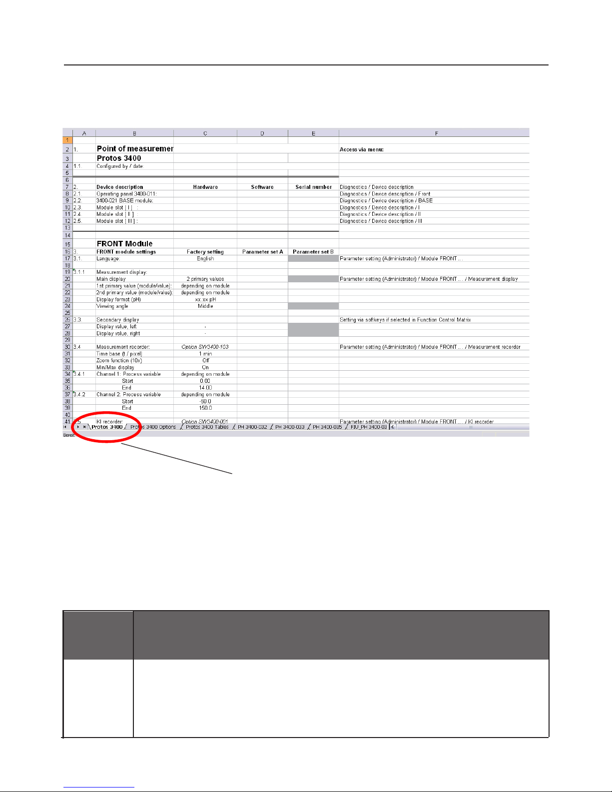
The Excel file provides one worksheet for each module with columns for the
following parameters: Factory settings, parameter set A, parameter set B.
Enter your settings as parameter set A or B.
The gray cells in the parameter set B column cannot be modified since they
contain sensor-specific values which cannot be changed by parameter set
switchover. Here, the values listed under parameter set A apply.
Fig.: Download area at www.knick.de
Documenting Parameter Setting
Documenting
Page 44
44
Display
During parameter setting the "HOLD" mode is active.
HOLD. The NAMUR “HOLD” (function check) contact is active (factory setting: Module BASE,
Contact K2, N/O contact). Current output response is user-defined:
• Current meas.: The currently measured value appears at the current output
• Last usable value: The last measured value is held at the current output
• Fixed 22 mA: The output current is at 22 mA
Documenting Parameter Setting
From the application window of the Excel file, select the worksheet for the
module the parameter settings of which you want to document.
Set the parameters of the respective module and enter the selected values in
the corresponding cells of the module worksheet.
Caution!
Page 45
45
ProgaLog 3000 Software (Option)
for Configuration and Documentation
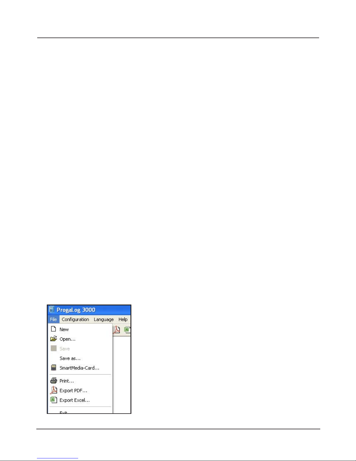
Fig.: ProgaLog 3000 menu: File
The ProgaLog 3000 software is available for convenient configuration of the
Protos 3400(X) process analysis system. The user interface can be switched
to the Protos display languages English, German, French, Spanish, Italian, or
Swedish. The software comes on CD-ROM. It runs under Windows® XP / Vista/
2000. A card reader for SmartMedia cards is required for transferring the
configuration files between PC and Protos 3400.
Configuration with ProgaLog 3000
Insert a SmartMedia card formatted as "memory card" into the analyzer.
First, the configuration data are written to the SmartMedia card.
These data can then be read and edited by the ProgaLog 3000 software.
1. Save the configuration data at the Protos 3400(X)
Parameter setting/System control/Copy configuration.
With “Save“ configuration, the complete device configuration
(except the passcodes) is written on the memory card.
2. Close and remove the SmartMedia card
Select "Maintenance / Close memory card", then remove the card.
3. Read out SmartMedia card with "ProgaLog 3000"
Open the "File / SmartMediaCard" menu of the
ProgaLog 3000 software to read out the configuration data stored on the SmartMedia card.
Now, you can edit all parameters at your PC.
Save the edited configuration file to the
SmartMedia card. Then, insert the SmartMediaCard into the Protos 3400(X) analyzer.
Page 46
46
ProgaLog 3000 Software
for Configuration and Documentation
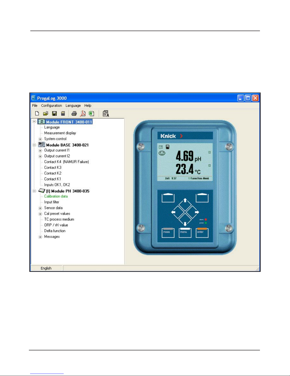
Fig.: ProgaLog 3000 configuration data
4. Edit configuration data using ProgaLog 3000
When the configuration data have been loaded, the software lists the
connected modules with all available configuration parameters:
The parameters are listed according to the modular device structure.
All configuration parameters (except the "Sensor data details", which are determined by digital sensors) can be edited at the PC.
After having finished the configuration, save the data to the SmartMedia card.
Page 47
47
Return
25.6 °C
7.00 pH
Identical module equipment
required for transfer
Copy configuration (Adminstrator)
Save
Save
Configuration
Load
6. Load the configuration data to the
Protos 3400(X)
Parameter setting / System control /
Copy configuration.
Select “Load configuration” to write the complete
device configuration (except the passcodes) to
the Protos 3400(X).
ProgaLog 3000 Software
for Configuration and Documentation
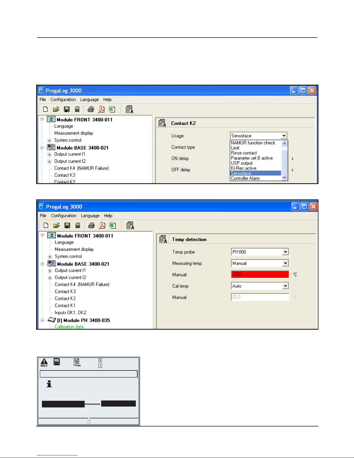
Input errors are indicated by red highlighting:
Configuring the parameters, e.g. relay contact usage:
5. Save the configuration data to SmartMedia card
Page 48
48
ProgaLog 3000 Software
for Configuration and Documentation
Configuration using "ProgaLog 3000"
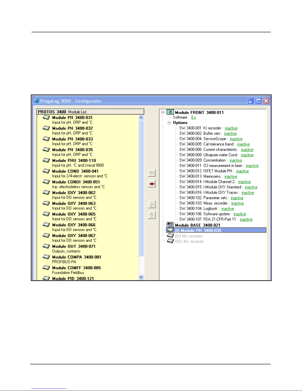
In the "Configurator" menu you can preconfigure a complete Protos 3400(X)
process analysis system with up to 3 modules at your PC.
1. Select your configuration from the modular system components offered in
the left-hand field.
2. Click the right arrow (-->) to add the components or remove components by
clicking (<--).
3. Now configure the parameters for the selected system components.
4. Save the configuration.
You can save the configuration to a memory card that has been preformat-
ted in the Protos 3400(X) and transfer them to analyzers with identical module configurations.
Page 49
49
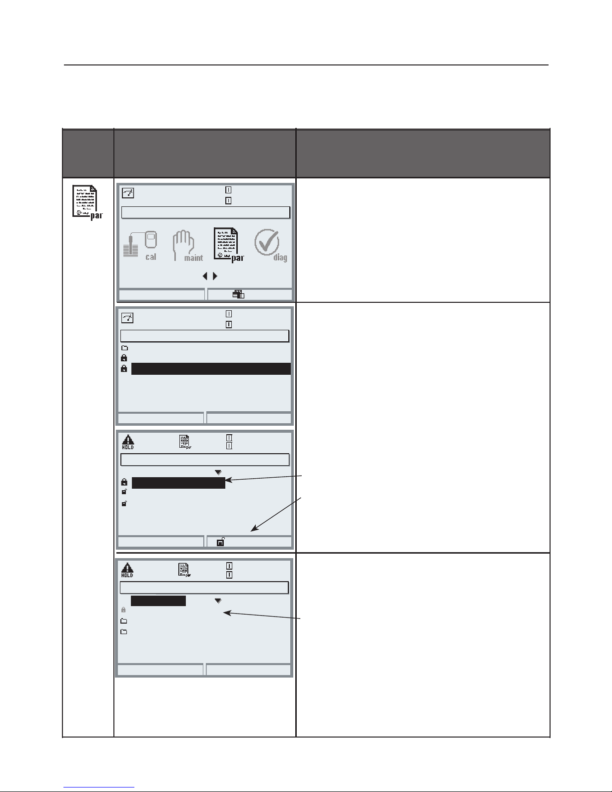
Menu
Display
Viewing level, Operator level,
Administrator level
Open parameter setting
From the measuring mode:
Press menu key to select menu.
Select parameter setting using arrow
keys, press enter to confirm.
Administrator level
Access to all functions, also passcode
setting.
Releasing or blocking a function for
access from the Operator level.
Parameter Setting: Operating Levels
Viewing level, Operator level, Administrator level
Note: HOLD mode active
Functions which can be blocked for
the Operator level are marked with the
"lock" symbol.
The functions are released or blocked
using the softkey.
Operator level
Access to all functions which have been
released at the Administrator level.
Blocked functions are displayed in gray
and cannot be edited (Fig.).
Viewing level
Display of all settings.
No editing possible!
Menu selection
Return to meas
25.6 °C
7.00 pH
Select:
[enter]
Lingua
Parameter setting
Return
25.6 °C
7.00 pH
Viewing level
Administrator level
(All Data) adm
(Operation Data) opl
(All Data) view
Operator level
Module FRONT (Administrator)
Return
25.6 °C
7.00 pH
Languages
Measurement display
KI recorder
English
Measurement recorder
Release
Module FRONT
Return
25.6 °C
7.00 pH
Measurement display
KI recorder
English
Measurement recorder
Languages
Page 50
50
Menu Display
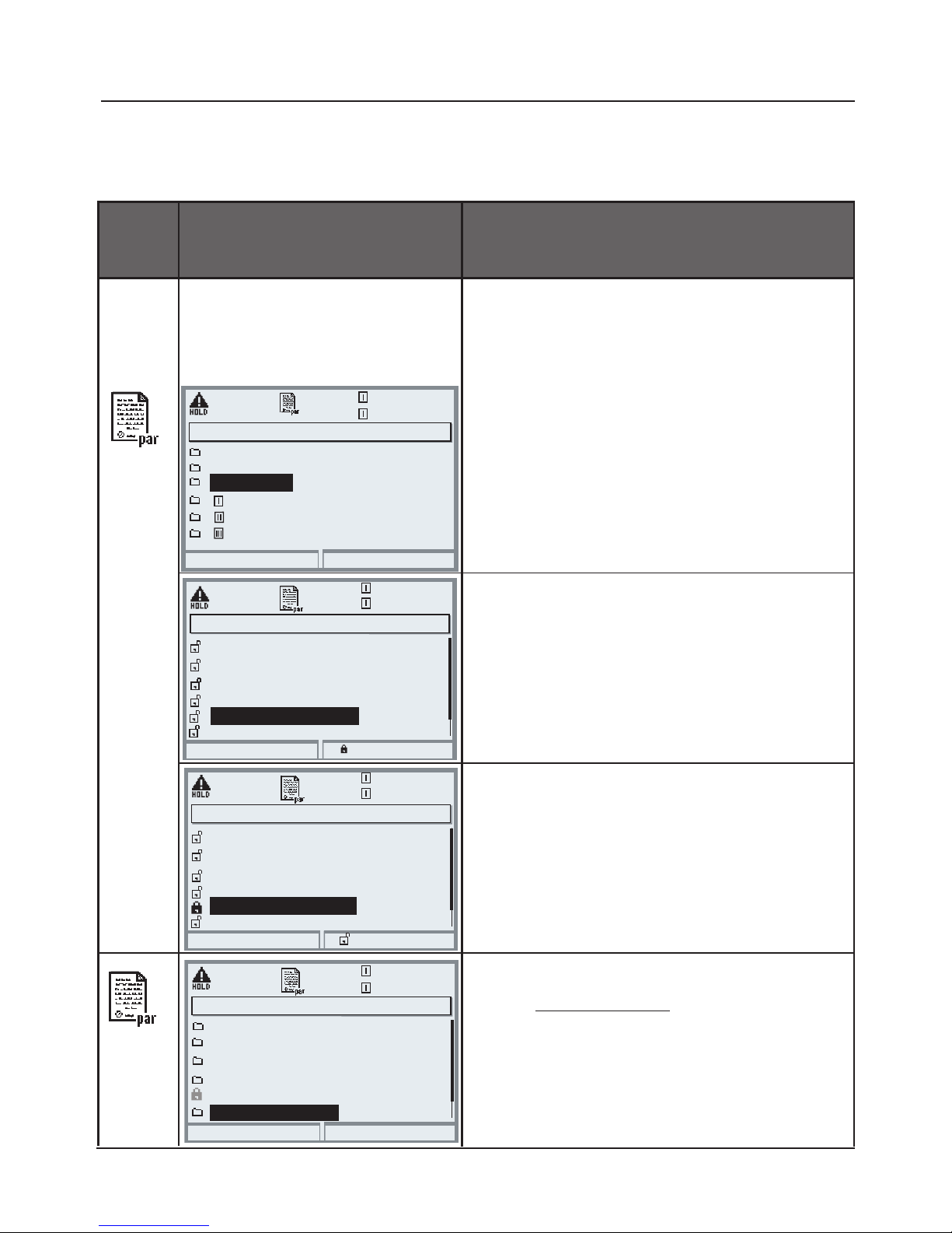
Administrator level:
Enabling / locking a function
Example: Blocking access to the configuration
of relay contact K1 (BASE module) from the
Operator level
Open parameter setting
Select Administrator level.
Enter passcode (1989).
Select “Module BASE”
using arrow keys,
press enter to confirm.
Parameter Setting: Locking a Function
Administrator level: Enabling/locking functions for Operator level
Note: HOLD mode active
25.6 °C
7.00 pH
Module FRONT
Module PH 3400-032
Module PH 3400-032
Module BASE
Module COND 3400-041
System control
Module BASE (Administrator)
Return
Contact K2 (NAMUR HOLD)
Contact K4 (NAMUR Failure)
Contact K3 (NAMUR maintenance)
Output current I2
Contact K1 (Limit)
Inputs OK1, OK2
Block
Module BASE (Administrator)
Return
Contact K2 (NAMUR HOLD)
Contact K4 (NAMUR Failure)
Contact K3 (NAMUR maintenance)
Output current I2
Contact K1 (Limit)
Inputs OK1, OK2
Release
Module BASE
Return
Contact K2 (NAMUR HOLD)
Contact K4 (NAMUR Failure)
Contact K3 (NAMUR maintenance)
Output current I2
Contact K1 (Limit)
Inputs OK1, OK2
Select “Contact K1” using arrow keys,
“Block” with softkey.
Now, the “Contact K1” line is marked
with the “lock” icon.
This function cannot be accessed from
the Operator level any more.
The softkey function changes to
“Release”.
Open parameter setting
Select Operator level, passcode (1246).
Select “Modul BASE”.
Now, the locked “Contact K1” function
is displayed in gray and marked with
the “lock” icon.
Parameter setting (Administrator)
Lock Functions
25.6 °C
7.00 pH
25.6 °C
7.00 pH
25.6 °C
7.00 pH
Page 51
51
Menu Display
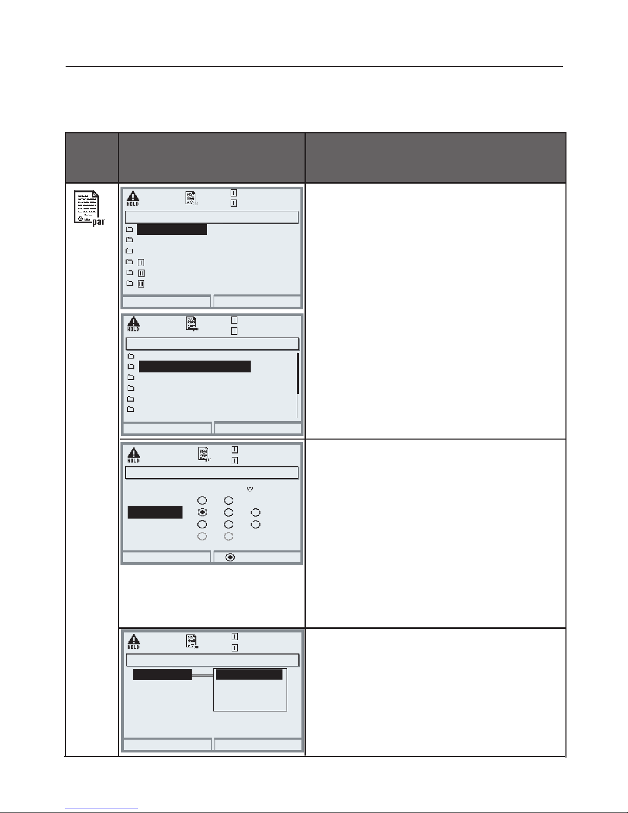
Function control matrix,
Time/Date
Activate parameter setting
Select Administrator level.
Enter passcode (1989).
Select system control using arrow keys,
confirm with enter.
Submenus of system control:
• Parameter sets
• Function control matrix
• Time/date
• Point of measurement
• Release of options
• Factory setting
• Passcode entry
• Software update ... more, depending on Options.
Function control matrix
Clear assignment of function
(parameter sets, KI recorder,
Favorites menu, Unical control)
to control element
(optocoupler, softkey or Profibus).
Time/Date
Selection of date format,
entering time and date
Return
Module FRONT 3400-011
Module PH 3400-032
Module PH 3400-032
Module BASE 3400-021
Module COND 3400-041
Return
Parameter sets
Point of measurement
Release of options
Time/date
Factory setting
System control
Function control matrix
Abort
Time
OK
DD,MM,YY
Date format
Date
DD/MM/YY
MM/DD/YY
YY-MM-DD
Input OK2
Return
Connect
Function control matrix (Administrator)
Left softkey
Right softkey
Profibus DO 2
ParSet KI rec. Fav Unical
– –
–
–
––
Weekday
Time/Date (Administrator)
Function Control Matrix, Time/Date
Select menu: Parameter setting/System control
Note: HOLD mode active
Parameter setting (Administrator)
System control (Administrator)
Function control matrix (Softkey
usage)
Time/date
25.6 °C
7.00 pH
25.6 °C
7.00 pH
25.6 °C
7.00 pH
25.6 °C
7.00 pH
Page 52
52
Menu
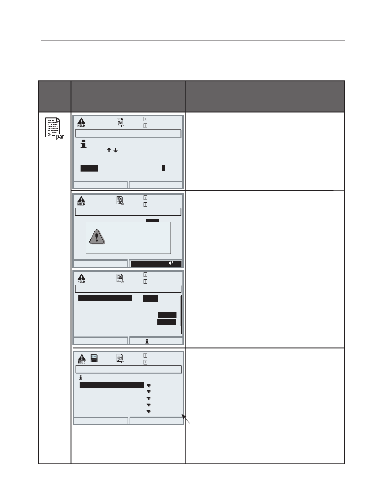
Display
Meas point description,
Passcodes, Release of options
Point of meas description
You can enter a tag number or notes
(e.g. date of last maintenance).
Point of Measurement, Passcodes, Release of
Options
Select menu: Parameter setting/System control
Note: HOLD mode active
Passcode entry
Passcodes (factory settings):
Calibration 1147
Maintenance 2958
Operator level 1246
Administrator level 1989
Caution
If you lose the Administrator passcode,
system access is locked!
Release of options
When you have purchased an option to be
released via TAN:
• Parameter setting, Administrator
• System control
• Select "Release of options"
Set option to “active”. Enter the TAN
at the prompt. The option is available
after the TAN has been entered.
Enter 0...9A...Z-+/
Abort
OK
using
Meas. point
M402.......................
Note
MAINT...07/03/07...
Passcode entry (Administrator)
OK
Passcode entry (Administrator)
Return
Info
cal
Calibration
On
Off
maint
Maintenance
On
Off
Change passcode
opl
Operator level
1147
On
Off
Close
cal
Calibration
On
maint
opl
Off
If you lose your
adm passcode, system
access will be locked.
Release of options (Administrator)
Return
002 Buffer sets
001 KI recorder
005 Cal tolerance band
004 ServiceScope
006 Current characteristic
Inactive
Inactive
Inactive
Inactive
Inactive
adm
Administrator level
Passcode entry
Point of measurement
Release of options (additional
functions)
25.6 °C
7.00 pH
25.6 °C
7.00 pH
25.6 °C
7.00 pH
25.6 °C
7.00 pH
SW 3400-xxx
Point of meas description (Administrator)
Page 53
53
Menu
Display
Factory setting, logbook
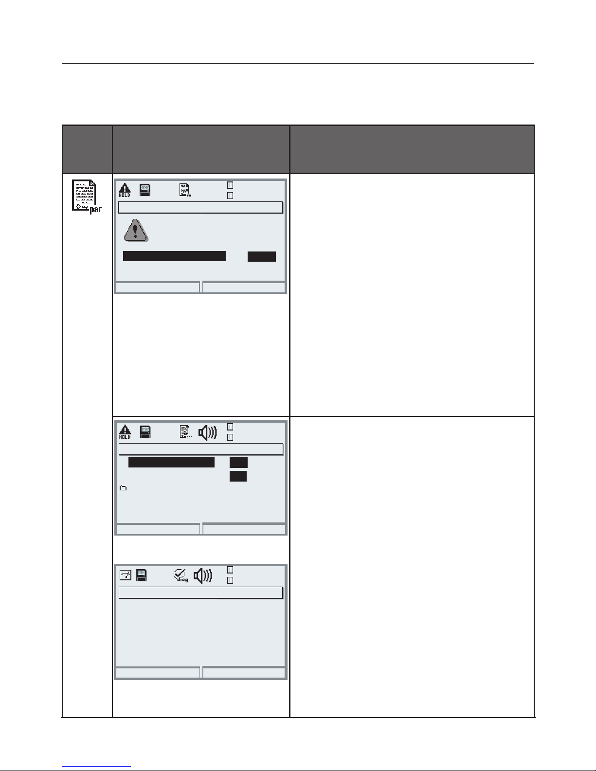
Factory setting
When this menu is opened, the
analyzer displays a warning (Fig.).
• For factory settings, see module
description
(Free download available at:
www.knick.de)
Factory Setting, Logbook
Parameter setting/System control/Logbook
Note: HOLD mode active
Logbook
Select which messages are to be
logged in the logbook. The last 50
events are recorded with date and
time.
This permits quality management
documentation to ISO 9000 et seq.
The logbook can be called from the
diagnostics menu (Fig.).
Additional function SW 3400-104:
Extended logbook for recording data
on SmartMedia card (TAN).
Factory setting (administrator)
Return
The factory setting erases
all your set parameters!
Set factory setting
No
Yes
Logbook (Administrator)
Return
Erase logbook
No
Log failure
Log warning
Yes
No
Yes
Logbook
Return
04/13/07 09:50 Measurement active
04/12/07 17:52 Measurement active
04/12/07 17:44 Parameter setting active
04/13/07 09:36 Parameter setting active
04/12/07 17:04 Measurement active
04/12/07 17:40 Wrong passcode
04/12/07 16:53 Diagnostics active
Logbook
Factory setting
25.6 °C
7.00 pH
25.6 °C
7.00 pH
25.6 °C
7.00 pH
Page 54
54
Language, Measurement Display, Viewing Angle
Parameter setting/Module FRONT
Note: HOLD mode active
Menu
Display
Language, Measurement
display, Viewing angle
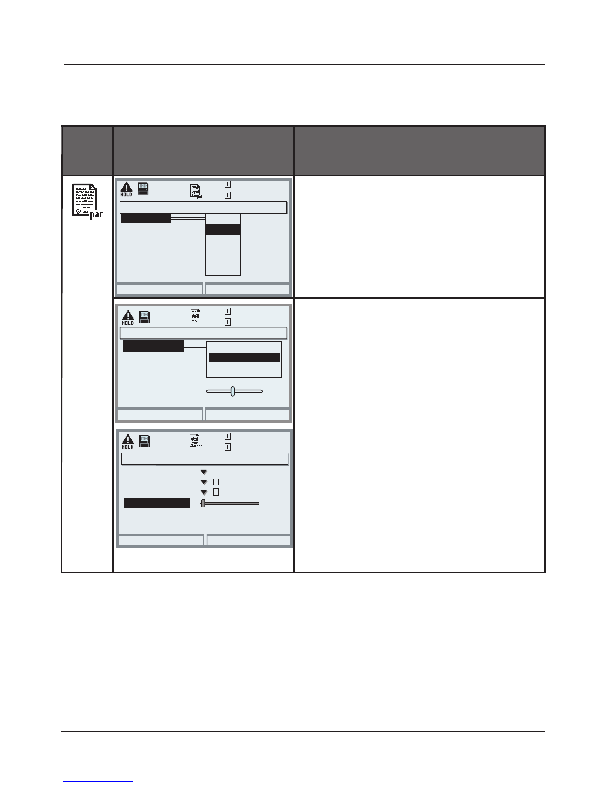
Language setting
• Open parameter setting
• Select "Module FRONT"
• Open “Languages”
Measurement display
• Open parameter setting
• Select "Module FRONT"
• Open “Measurement display”
• Select number and type
of values to be displayed
Viewing angle
• Open parameter setting
• Select "Module FRONT"
• Open “Measurement display”
• Adjust display to local light
conditions
• Confirm with enter.
Module FRONT (Administrator)
Abort
Measurement display
Français
Italiano
English
OK
Languages
Deutsch
Measurement record
KI recorder
Svenska
Español
1 primary value
1st primary value
Viewing angle
2nd primary value
2 primary values
Abort
OK
Main display
Module FRONT (Administrator)
Return
Main display
1st primary value
2nd primary value
Viewing angle
2 primary values
S/cm
°C
Languages
Measurement display
Measurement display (Administrator)
Parameter setting: "Module
FRONT"
25.6 °C
7.00 pH
25.6 °C
7.00 pH
25.6 °C
7.00 pH
Page 55
55
Calculation Blocks (System Control)
Select menu: Parameter setting/System control/Calculation Blocks
Calculation of new variables from measured variables
Calculation Blocks
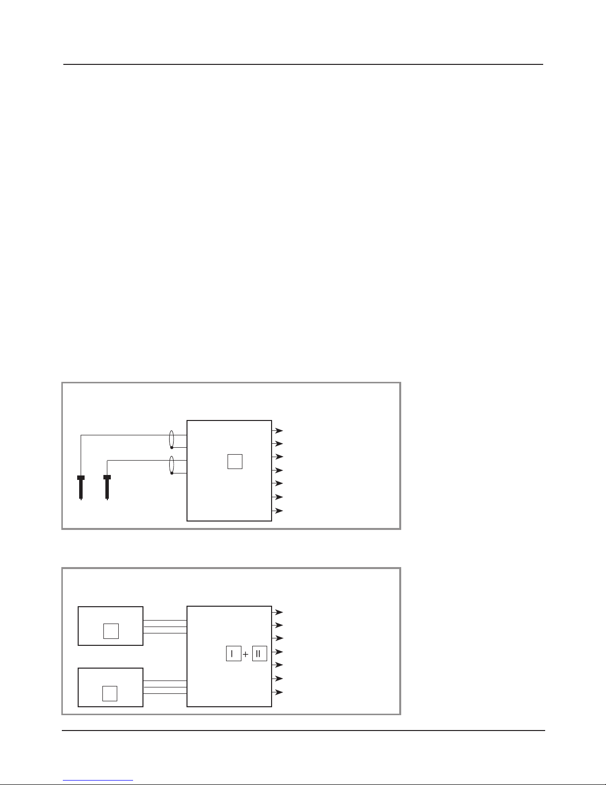
Two measuring modules with all their measured values serve as input for the
calculation block. In addition, the general device status (NAMUR signals) is
taken into account. The following variables are calculated from the existing
values:
• Ratio
• Pass (passage)
• Reject (rejection)
• Measured-value difference
• Deviation
• pH value calculation by means of dual conductivity measurement
These output variables are then available in the system and can be assigned to
the outputs (current, limit values, display ...)
Calculation Block
Module I
e.g.:
pH measuring
module
Inputs:
Sensors, terminals
Outputs
Meas. values / Status
pH
Temp
pH
mV
ORP
°C
rH
Mohm
kohm
Measuring
module
Module
pH / pH
Inputs:
Outputs of 2 measuring modules
Outputs:
Meas. values / Status
Module
I
pH diff
ORP diff
°C diff
.
.
.
.
Calculation
Block
Module
II
Functionality of Measuring Module
Functionality of Calculation Block
Page 56
56
System control
Combining measuring modules
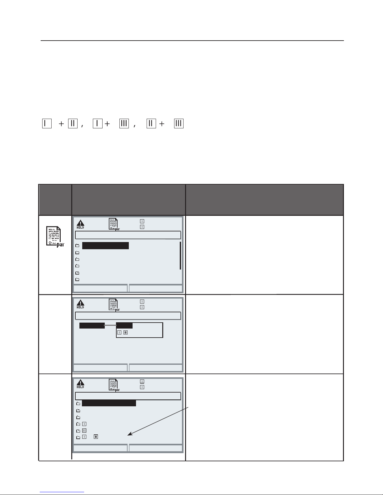
With three measuring modules the following Calculation Block combinations
are possible:
Activating Calculation Blocks
Select menu: Parameter setting/System control/Calculation Blocks
Combining measuring modules to Calculation Blocks
Menu Display
Activating Calculation Blocks
Calculation Blocks
• Open parameter setting
• System control
• Select “Calculation Blocks”
• Depending on the modules installed,
the possible combinations for
Calculation Blocks are offered.
Return
25.6 °C
7.10 pH
Point of measurement
Logbook
Concentration table
Release of options
Calculation Blocks
Buffer table
System control (Administrator)
Return
25.6 °C
7.10 pH
Block 2
Block 1
Calculation Blocks (Administrator)
Off
Calc pH/pH
During parameter setting the
Calculation Blocks are displayed like
modules.
Return
25.6 °C
7.10 pH
Module FRONT 3400-011
Module PH 3400-032
Module PH 3400-032
Module BASE 3400-021
Calc pH/pH
+
Parameter setting (Administrator)
Two Calculation Blocks can be activated.
Page 57

57
Overview of Calculation Blocks
Module combinations, Calculation Block, process variables
Module
combination
Calculation Block Variables calculated by the
Calculation Block
New process variables and signal processing
Current outputs
All current outputs can be set to output the new process variables formed by
the Calculation Blocks.
Measurement display
All new process variables can be displayed as primary or as secondary value.
Controller
Controller functions are not supported.
pH + pH Calc pH/pH Difference
Difference
Difference
Cond + Cond
CondI + CondI
Cond + CondI
Calc Cond/Cond Difference
Difference
Difference
Ratio
Passage (Pass)
Rejection (Reject)
Deviation (Deviat)
Oxy + Oxy Calc Oxy/Oxy Difference
Difference
Difference
Difference
Difference
pH
ORP
°C
S/cm
Ohm*cm
°C
S/cm []
S/cm[%]
S/cm[%]
S/cm[%]
%Air
%O
2
g/l
ppm
°C
Page 58
58
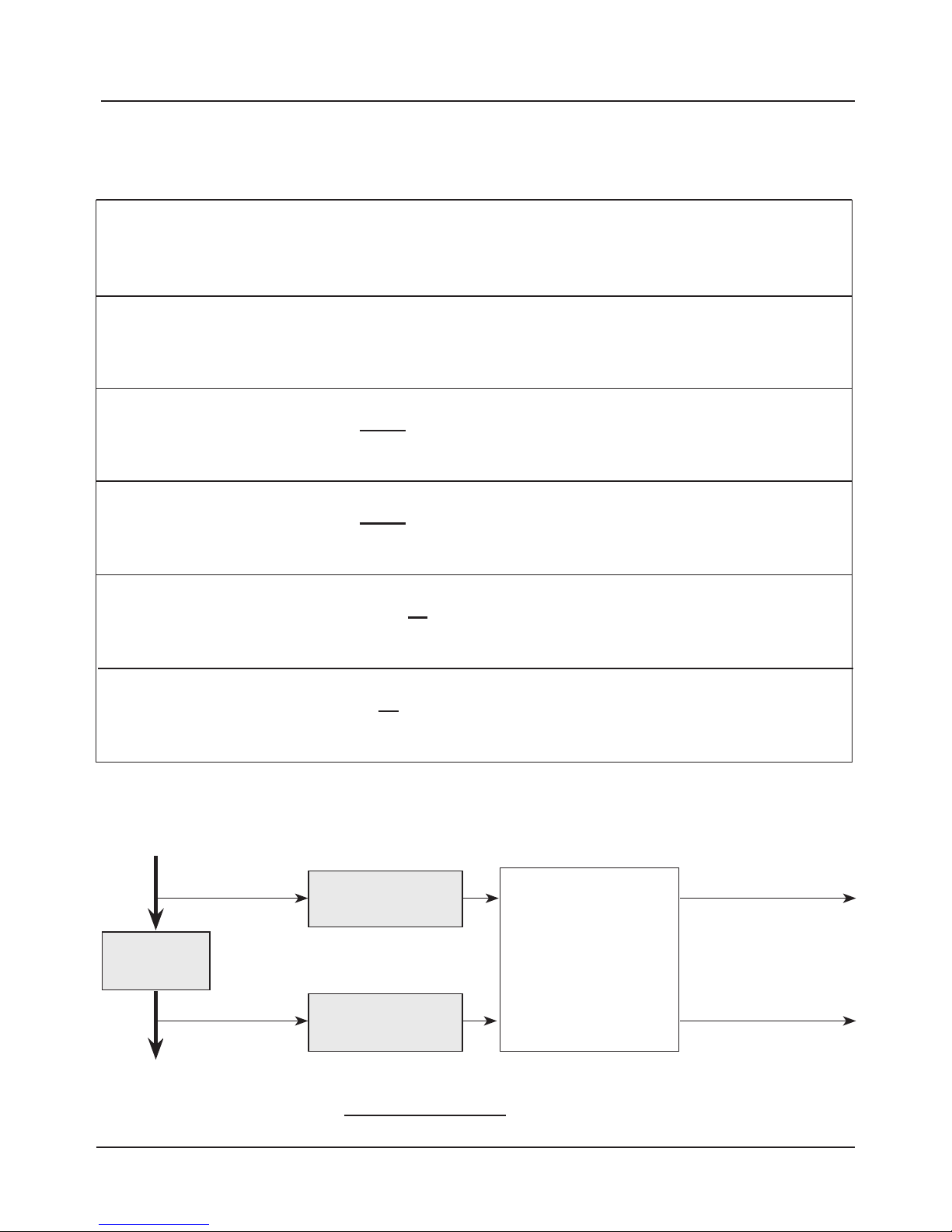
Calculation Formulas
Module combinations, Calculation Block, process variables
Variable Calculation formula Range Span
Difference
(selectable in menu)
DIFF = A - B
or
DIFF = B - A
Variable Variable
Ratio
(selectable in menu)
RATIO =
0.00 ... 19.99 0.10
A
B
Passage
PASS = • 100
0.00 ... 199.9 10 %
B
A
Rejection
REJECT=
(
1- ) 100 %
-199.9 ... 199.9 10 %
B
A
Deviation
DEVIAT=
(
-1) 100 %
-199.9 ... 199.9 10 %
B
A
c (NaOH) [mmol/l]
Secondary display
only
Cation
exchanger
COND1 module
COND 3400-041
COND2 module
COND 3400-041
Calculation Block
pH
H2O
COND measuring
point 1
COND measuring
point 2
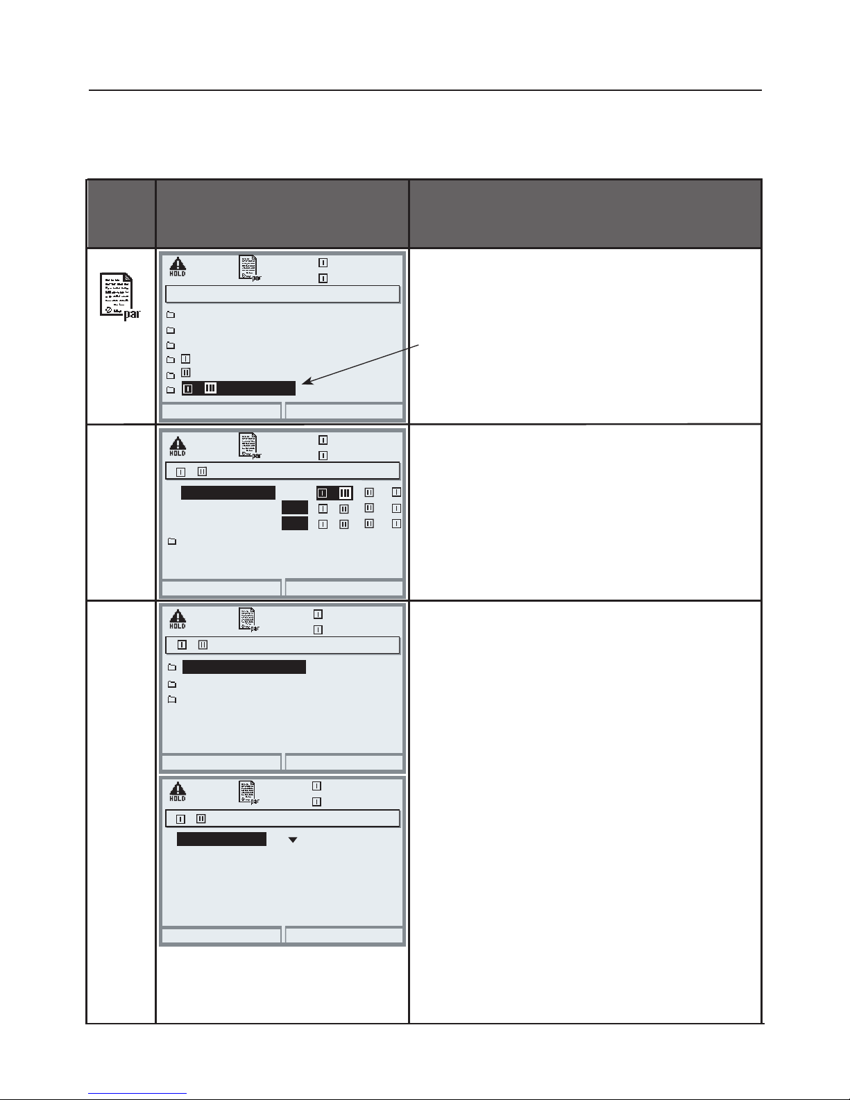
pH value calculation by means of dual conductivity measurement
See user manual for COND 3400-041 module. Principle:
c(NaOH) =
COND1- 1/3 COND2
243
pH = 11+log[c(NaOH)]
Page 59
59
Configuring a Calculation Block
Select menu: Parameter setting/System control/Calculation Blocks
Setting the process variable to be calculated
Return
25.6 °C
7.20 pH
Module FRONT 3400-011
Module PH 3400-032
Module PH 3400-032
Module BASE 3400-021
Calc pH/pH
+
Menu Display
Configuring a Calculation Block
Select Calculation Block
• Open parameter setting
• System control
• Select module
• Depending on the modules installed,
the possible combinations for
Calculation Blocks are offered.
Messages
You can activate messages for the
selected variables.
Variables which have been set as “Off”
cannot be processed further.
The measured values which shall
release a message are set using the
arrow keys
(left/right: select position,
up/down: edit number).
Confirm with enter.
+ Calc pH/pH (Administrator)
Return
25.6 °C
7.20 pH
Difference ORP
Messages
Difference °C
Difference pH
–
Off
–
–
Off
Off
–
–
–
+ Messages (Administrator)
Return
25.6 °C
7.20 pH
Messages ORP diff
Messages Temp diff
Messages pH diff
+ Messages pH diff (Administrator)
Return
25.6 °C
7.20 pH
Failure Limit Lo
Warning Limit Hi
Warning Limit Lo
Monitoring
Variable limits
Failure Limit Hi
-01.00 pH
-00.50 pH
+00.50 pH
+01.00 pH
System control
Parameter setting (Administrator)
Page 60
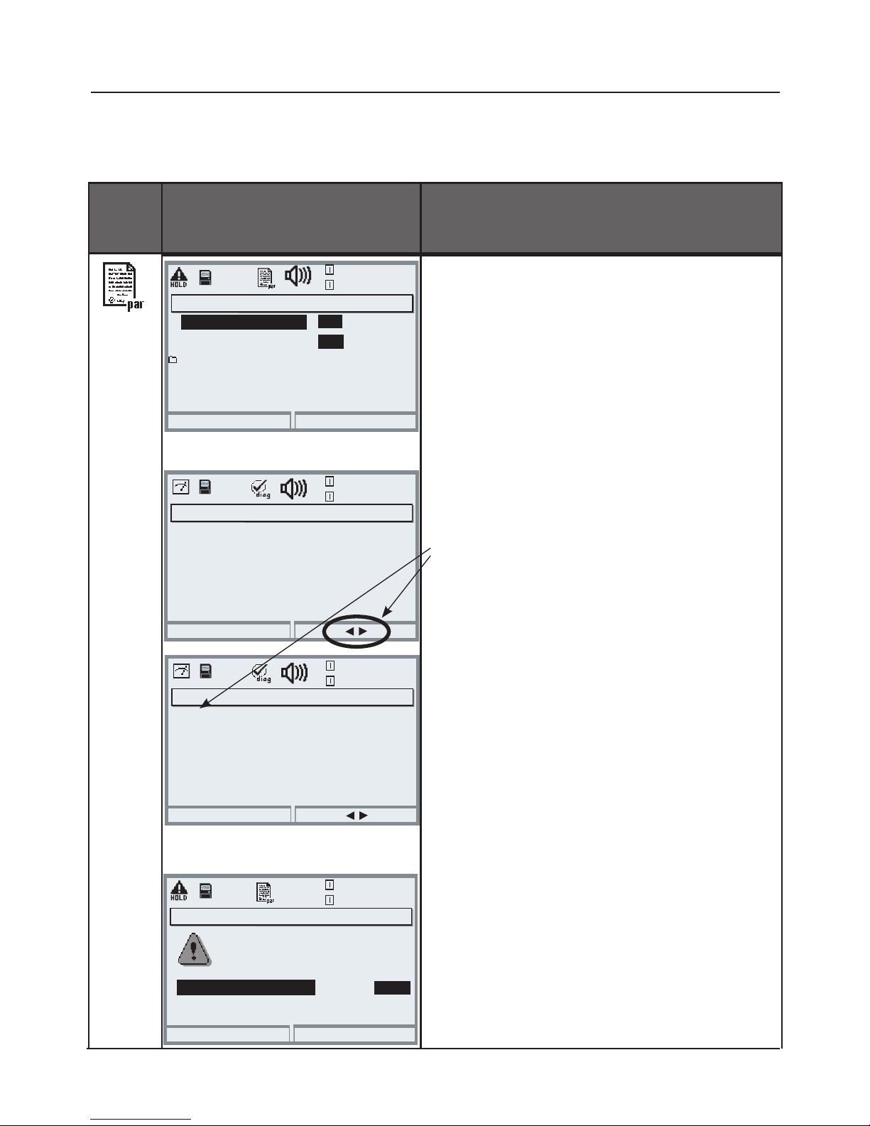
60
Menu
Display Logbook, Factory setting
Logbook, Factory Setting
Parameter setting/System control/Logbook
Note: HOLD mode
Logbook
Select which messages are to be
logged in the logbook.
The last 50 events are recorded with
date and time.
This permits quality management
documentation to ISO 9000 et seq.
The logbook can be called from the
diagnostics menu (Fig.).
Pressing the right softkey displays the
message identifier.
Additional function SW 3400-104:
Extended logbook for recording data
on SmartMedia card (TAN).
Logbook (Administrator)
Return
Erase logbook
No
Log failure
Log warning
Yes
No
Yes
Logbook
Return
04/13/10 09:50 Measurement active
04/12/10 17:52 Measurement active
04/12/10 17:44 Parameter setting active
04/13/10 09:36 Parameter setting active
04/12/10 17:04 Measurement active
04/12/10 17:40 Wrong passcode
04/12/10 16:53 Diagnostics active
Factory setting
Allows resetting the parameters to
their factory setting. When this menu
is opened, the analyzer displays a
warning (Fig.).
Factory setting (Administrator)
Return
The factory setting erases
all your set parameters!
Measuring system
No
Yes
Logbook
Factory setting
25.6 °C
7.00 pH
25.6 °C
7.00 pH
25.6 °C
7.00 pH
Logbook
Return
F223 04/13/10 09:50 Diagnostics active
F224 04/12/10 17:52 Measurement active
F222 04/13/10 09:36 Parameter setting active
25.6 °C
7.00 pH
Page 61
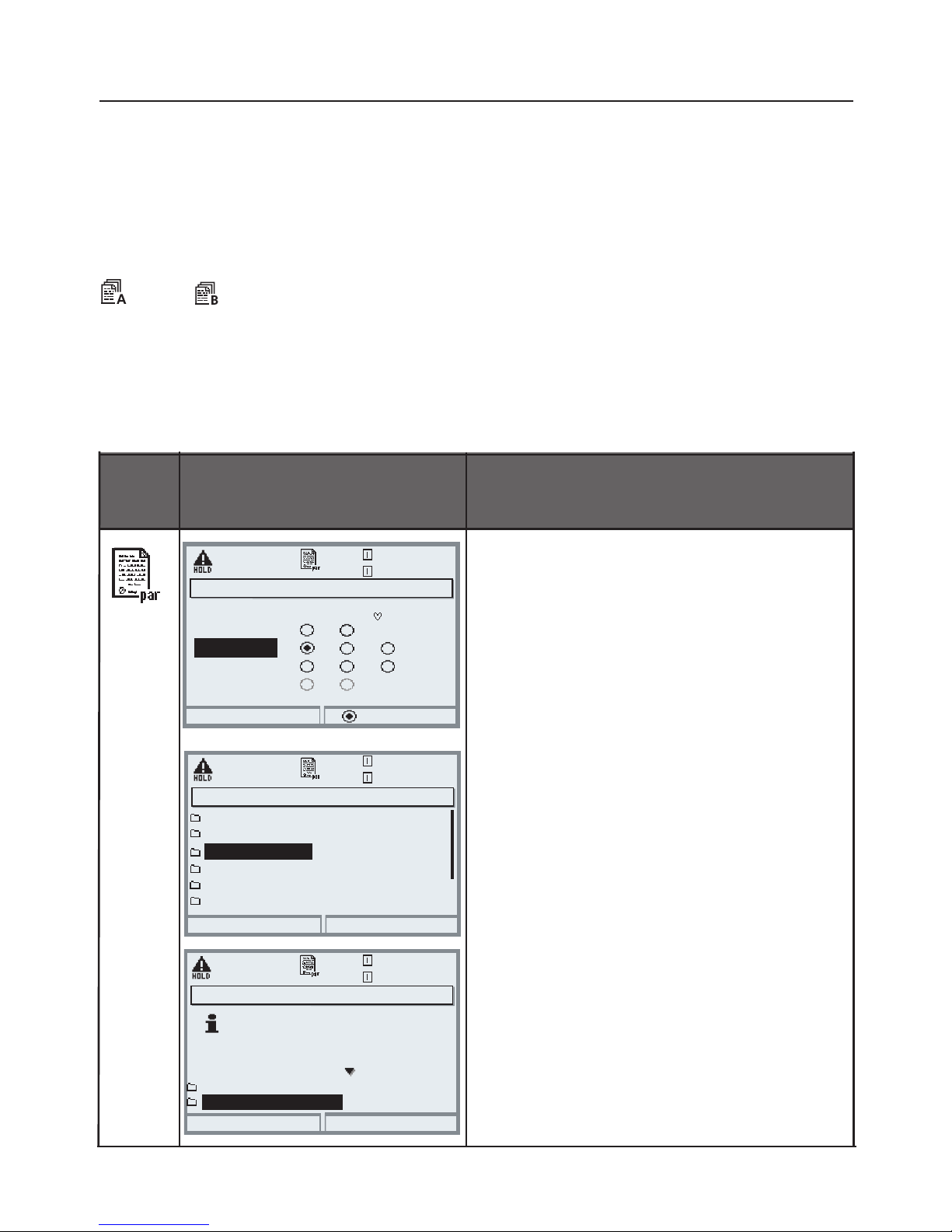
61
Parameter sets
Switching Between Parameter Sets A, B
Parameter setting/System control/Parameter sets
Excel “Parameter settings” spreadsheet at www.knick.de: Downloads
Menu Display
Select control element for switching
between the parameter sets
• Open menu selection
• Parameter setting, Admin. level
• Enter passcode
• System control:
Select “Function control matrix”
Parameter sets A, B
• Open menu selection
• Parameter setting, Admin. level
• Enter passcode
• System control
• Select “Parameter sets” menu and
confirm with enter.
• Save parameter set
The active parameter set A overwrites
the internal parameter set B.
• Load parameter set
Parameter set B is loaded.
Return
Copy configuration
Function control matrix
Time/date
Parameter sets
Point of measurement
Memory card
System control (Administrator)
Parameter Sets A, B
2 complete parameter sets (A, B) can be stored in the analyzer.
An icon in the measurement display shows which parameter set is active:
Input OK2
Return
Connect
Function control matrix (Administrator)
Left softkey
Right softkey
Profibus DO 2
ParSet KI rec. Fav Unical
– –
–
–
––
Return
For switchover, see
“Function control matrix”
Parameter sets
Save parameter set
A, B (internal)
Load parameter set
Parameter sets (Administrator)
Parameter sets A, B
Excel “Parameter settings” spreadsheet at www.knick.de: Downloads.
The control element for switching between the parameter sets (opto coupler,
softkey, or PROFIBUS) is selected at “Parameter setting/System control/Function
control matrix”. The currently activated set can be signaled by a relay contact.
or
25.6 °C
7.00 pH
25.6 °C
7.00 pH
25.6 °C
7.00 pH
Page 62
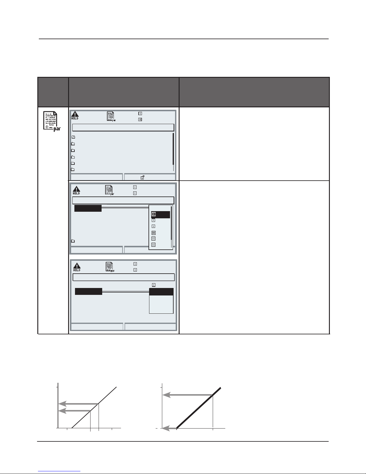
62
• Select Curve,
e.g. “linear”: The measured variable is
represented by a linear output current curve. The desired range of the
measured variable is specified by the
values for “Start” and “End”.
Current Outputs, Contacts, OK Inputs
Select menu: Parameter setting/Module BASE
Note: HOLD mode active
Menu
Display
Parameter setting
BASE module
• Select measured variable
Output current
[pH]
20
4
14
0
Assigning measured values: Start (4 mA) and End (20 mA)
[pH]
20
4
7
5
[mA]
Example 1: Range pH 0 - 14 Example 2: Range pH 5 - 7
Advantage: Higher resolution in range of interest
[mA]
To configure current output
• Call up parameter setting
• Enter passcode
• Select “Module BASE”
• Select “Output current I1”
To configure a current output
• Open parameter setting
• Enter passcode
• Select “Module BASE”
• Select “Output current ...”
Module BASE (Administrator)
19.2°C
Return
Contact K2 (NAMUR HOLD)
Contact K4 (NAMUR Failure)
Contact K3 (NAMUR maintenance)
7.00 pH
Output current I2
Contact K1 (Limit)
Inputs OK1, OK2
Block
Output current I1 (Administrator)
OK
19.0 °C
7.00 pH
Variable
Output
Abort
Curve
Linear
°C
Trilinear
Function
Table
Output current I1 (Administrator)
OK
19.0 °C
7.00 pH
Curve
Output
Behavior during messages
Start
Abort
Variable
°C
rH
S/cm
°C
g/kg
Off
pH
End
Start
End
Output filter
5 7
Current outputs
BASE module
Page 63

63
[%]
100
Start
End
0
Output current
Y
X
Process variable
[%]
100
Start
End
0
Output current
Y
X
Process variable
2nd vertex Y
1st vertex Y
2nd vertex X
1st vertex X
• Linear characteristic
The process variable is represented by a linear output current curve.
• Note: Bilinear characteristic
For a bilinear characteristic, identical parameters are entered for the two
vertices (1st vertex, 2nd vertex).
• Trilinear characteristic
Two additional vertices must be entered:
Current Outputs: Characteristics
Select menu: Parameter setting/Module BASE
Page 64
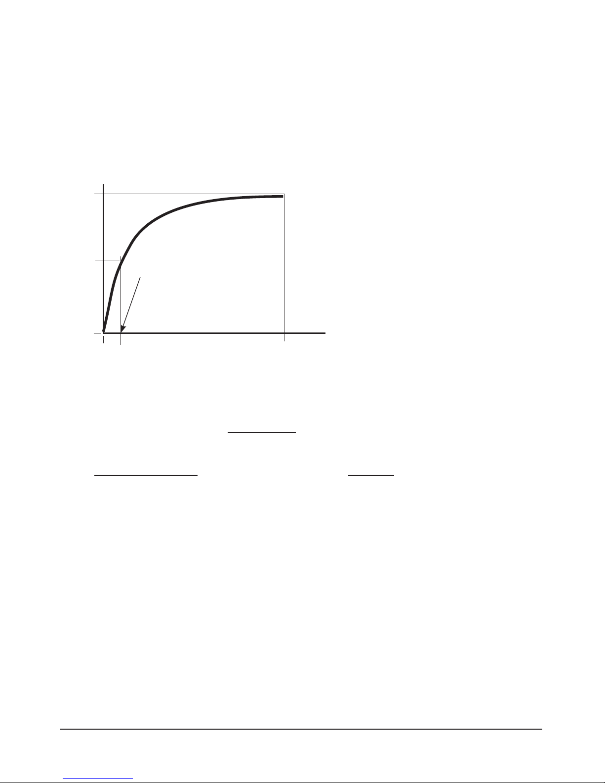
64
Output current (4 to 20 mA) = 16 mA + 4 mA
[%]
Entry for “50 % point”:
e.g.:
10 % of measured value
End
0
Output current
Y
X
Process variable
• Function characteristic
Nonlinear output current characteristic: allows measurements over several
decades, e.g. measuring very low values with a high resolution and high
values with a low resolution.
Required: Entering a value for 50 % output current.
100
50
Equation
(1+K)x
1+Kx
E + S - 2 * X50%
X50% - S
K =
M - S
E - S
x =
S: Start value at 4 mA
X50%: 50% value at 12 mA (output current range 4 to 20 mA)
E: End value at 20 mA
M: Measured value
Logarithmic output curve over one decade:
S: 10 % of maximum value
X50%: 31.6 % of maximum value
E: Maximum value
Logarithmic output curve over two decades:
S: 1 % of maximum value
X50%: 10 % of maximum value
E: Maximum value
Page 65
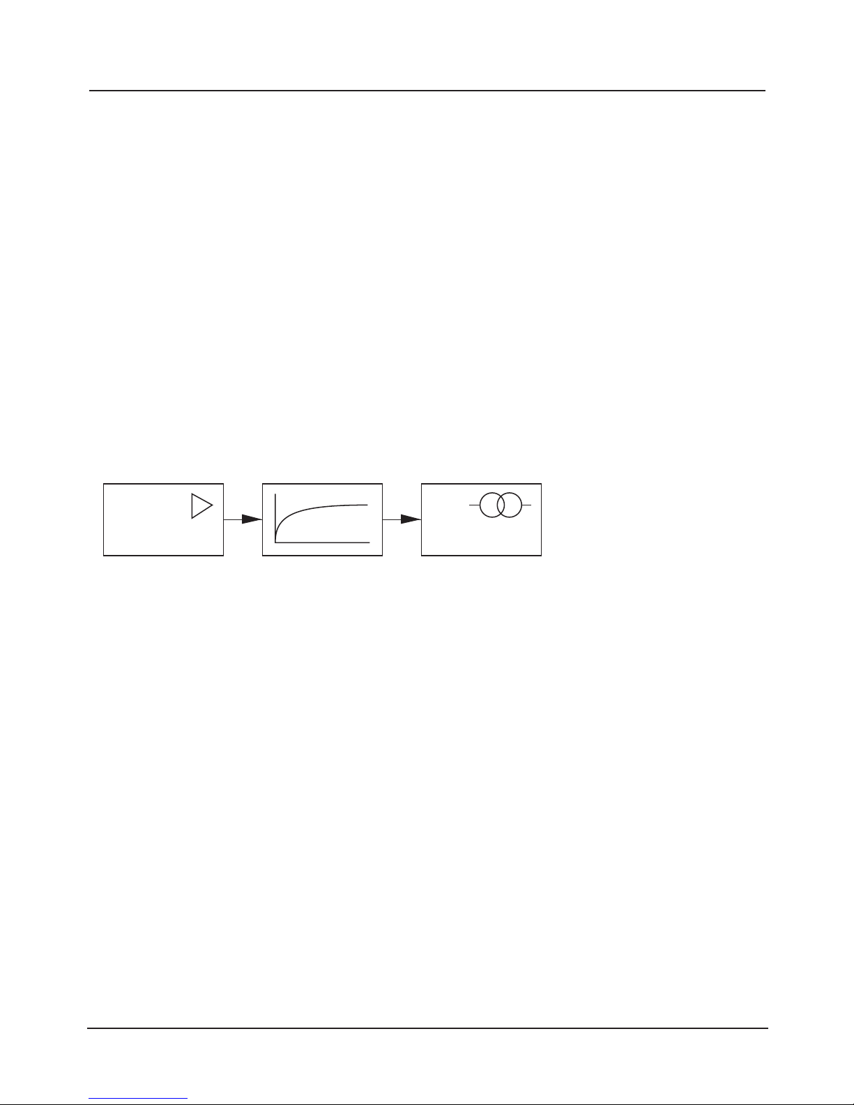
65
Output Filter
Time interval
Time averaging filter
To smoothen the current output, a low-pass filter with adjustable time interval
can be switched on. When there is a jump at the input (100 %), the output level
is at 63 % after the time interval has been reached.
The time interval can be set from 0 to 120 sec. If the time interval is set to 0 sec,
the current output follows the input.
Note:
The filter only acts on the current output and the current value of the secondary display, not on the measurement display, the limit values or the controller!
Time interval 0 ... 120 sec
Process variable
0 (4) - 20 mA
Page 66
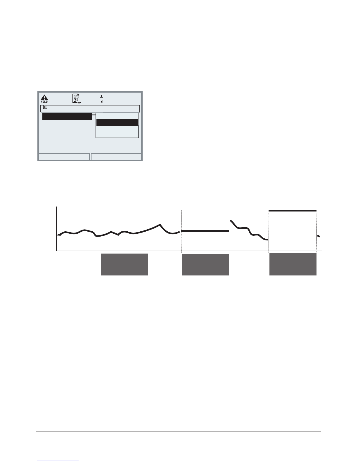
66
NAMUR Signals: Current Outputs
Behavior during messages: HOLD, 22mA signal
Behavior during messages
Output current
[mA]
“fix (22 mA)”
HOLD
22
4
“Last usable value”
HOLD
Depending on the configuration (“Messages”)
the current outputs switch to:
• Currently measured value
• Last measured value (HOLD function)
• Fixed value (22 mA)
In the case of a fault a 22 mA signal can be
generated for the selected process variable
(1st primary value).
HOLD
"Current meas."
Behavior during messages
OK
19.0°C
83.1 % Air
22mA message
Abort
HOLD
Fixed 22 mA
Current meas.
Last usable value
Message when the current range is exceeded
As delivered, the “Maintenance request” (Warn) message is generated when the
current range is exceeded (< 3.8 mA or > 20.5 mA).
This setting can be changed in the Parameter setting menu of the respective
measuring module at “Messages”.
To generate a “Failure” message, the limit value monitoring must be set to
“Variable limits”:
Parameter setting - <measuring module> - Messages - Variable limits -
Failure limit ...
Enter the same values for the failure limits as for the current output:
Parameter setting - Module BASE - Output current - Variable Start / End.
Current outputs: Behavior during messages
Page 67
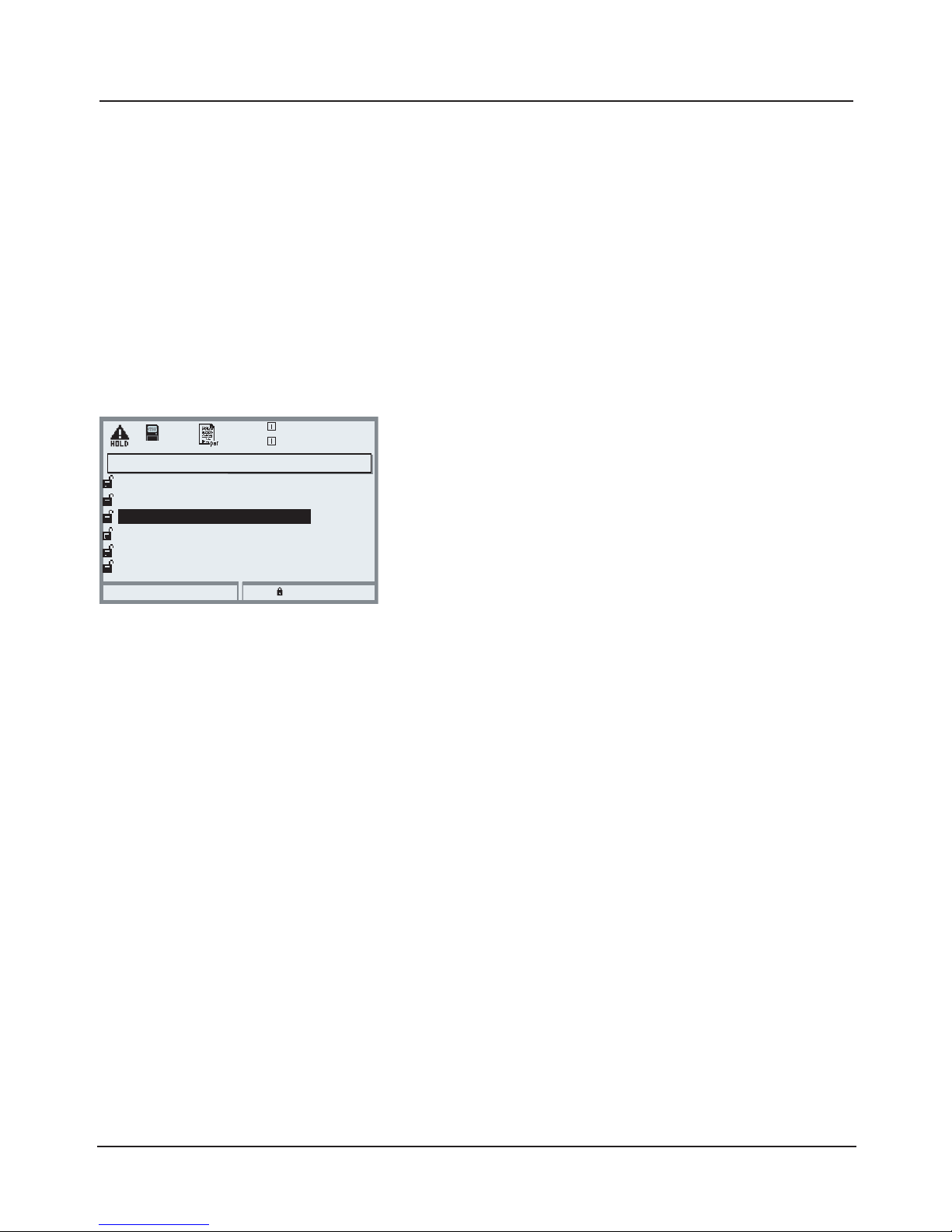
67
NAMUR Signals: Relay Contacts
Failure, maintenance request, HOLD (function check)
Failure is active
when a value has exceeded (or fallen below, resp.) a preset ”Failure Limit Hi”
or ”Failure Limit Lo”, when the measured value is out of range, or in the event
of other failure messages. That means that the equipment no longer operates
properly or that process parameters have reached a critical value.
Failure is disabled during "HOLD" (Function check).
Maintenance request is active
when a value has exceeded (or fallen below, resp.) a preset "Warning Limit Hi"
or "Warning Limit Lo", or when other warning messages have been activated.
That means that the equipment is still operating properly but should be serviced, or that process parameters have reached a value requiring intervention.
Warning is disabled during "HOLD" (function check).
HOLD is active:
• during calibration
• during maintenance (current source, meas. point maintenance)
• during parameter setting at the Operator level and the Administrator level
• during an automatic rinsing cycle
As delivered, the floating relay outputs of the BASE module are assigned to the
NAMUR signals:
Failure Contact K4, normally closed
(signaling current failure)
Maintenance request Contact K3, normally open contact
HOLD Contact K2, normally open contact
NAMUR signals: Factory setting of contacts
• Select parameter setting
• Administrator level
• Select “Module BASE” (Fig.)
You can define a delay time for “Maintenance request”
and “Failure”, resp.
If an alarm message is released, the contact will only be
activated after expiry of this delay time.
Module BASE (Administrator)
Output current I1
Return
Block
7.00 pH
Contact K4
Output current I2
Contact K3
19.0°C
(NAMUR failure)
Contact K2
Contact K1
(NAMUR maintenance)
(NAMUR HOLD)
(Limit)
Page 68
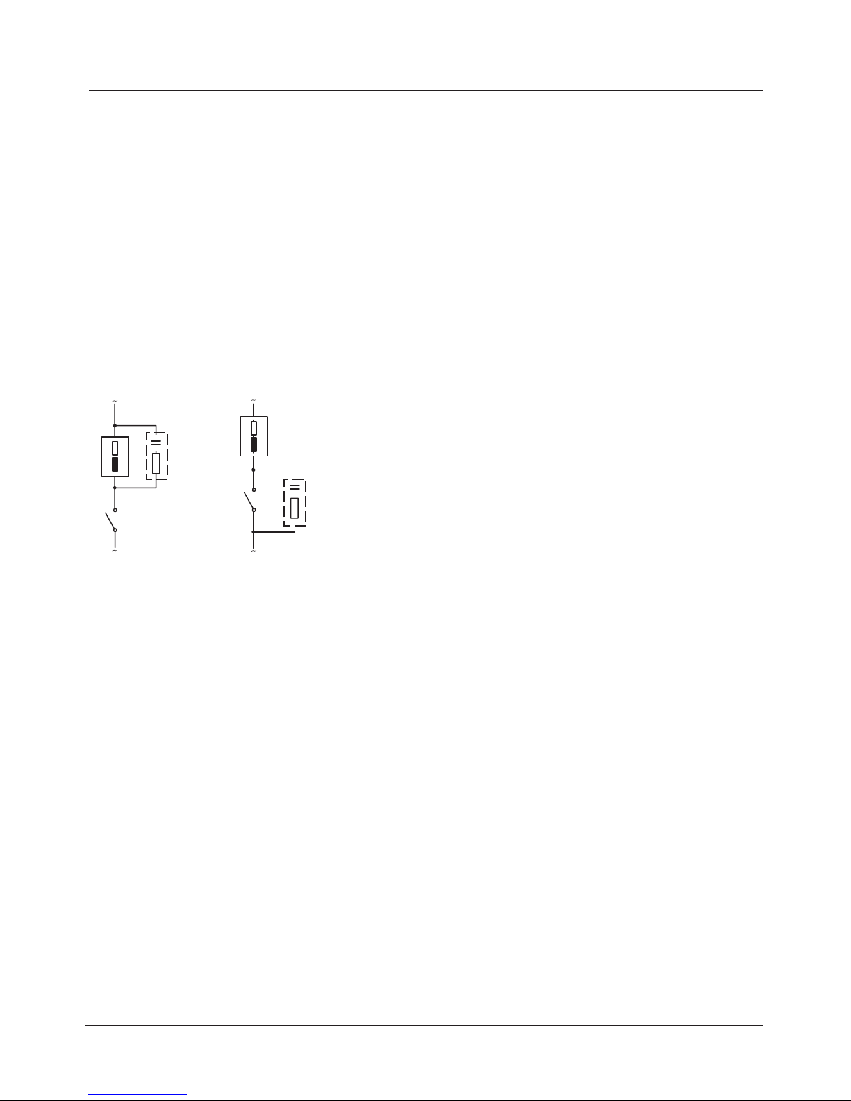
68
Relay Contacts: Protective Wiring
1
2
3
1
2
3
Typical AC applications
with inductive load
1 Load
2 RC combination, e.g. RIFA PMR 209
Typical RC combinations
e.g.
capacitor 0.1 µF
resistor 100 ohms / 1 W
3 Contact
Caution!
Make sure that the maximum ratings of the relay contacts are not exceeded
even during switching!
Protective wiring of relay contacts
Relay contacts are subject to electrical erosion. Especially with inductive and
capacitive loads, the service life of the contacts will be reduced. For suppression of sparks and arcing, components such as RC combinations, nonlinear
resistors, series resistors and diodes should be used.
Information concerning relay contacts
As delivered, the relay contacts are suitable for low signal currents (down to
approx. 1 mA). If currents above approx. 100 mA are switched, the gold plating
is destroyed during the switching process. After that, the contacts will not
reliably switch low currents.
Page 69
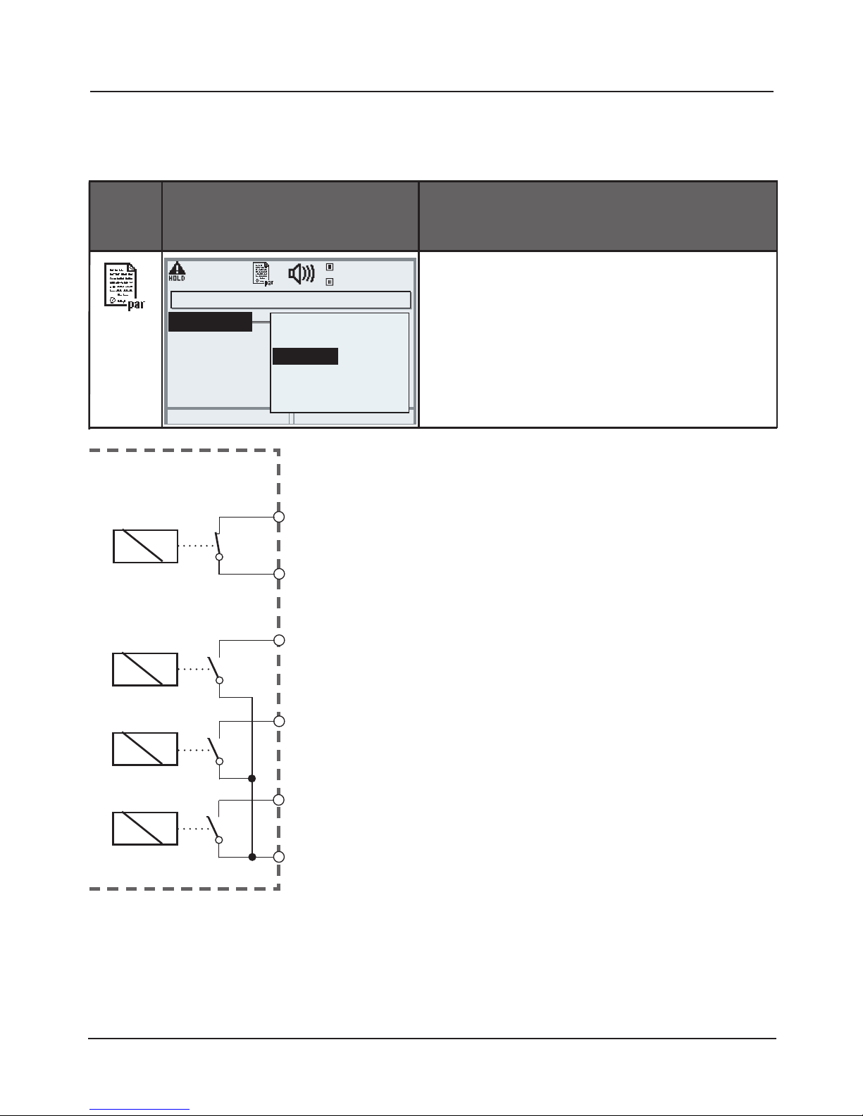
69
Relay Contacts
Parameter setting/Module BASE/Relay contacts
The BASE module provides 4 relay contacts
(max. AC/DC rating 30 V / 3 A each).
Contact K4 is provided for failure message. The
switching behavior (normally open or normally
closed), as well as a switch-on or switch-off
delay can be defined.
Default settings of the user-definable relay
contacts of the BASE module:
K3: NAMUR maintenance request
K2: NAMUR HOLD (function check)
K1: Limit value
K1-K3 are user definable (“Usage”):
• NAMUR maintenance
• NAMUR HOLD
• Limit value
• Rinse contact
• Parameter set B active
• USP output (COND module only)
• KI rec. active
• Sensoface
• Alarm control
Menu
Display Setting the relay contacts
Relay contacts, usage
• Open parameter setting
• Enter passcode
• Select “Module BASE”
• Select “Contact ...”
• “Usage” (Fig.)
Module BASE
K1
K2
K3
Contact K1 (Administrator)
19.2°C
Return
Hysteresis
Variable
Limit value
7.00pH
Usage
Effective direction
Contact type
Limit value
NAMUR maintenance
NAMUR HOLD
Rinse contact
Parameter set B active
USP output
Contact assignment:
See terminal plate of
BASE module
Relay contacts
Page 70
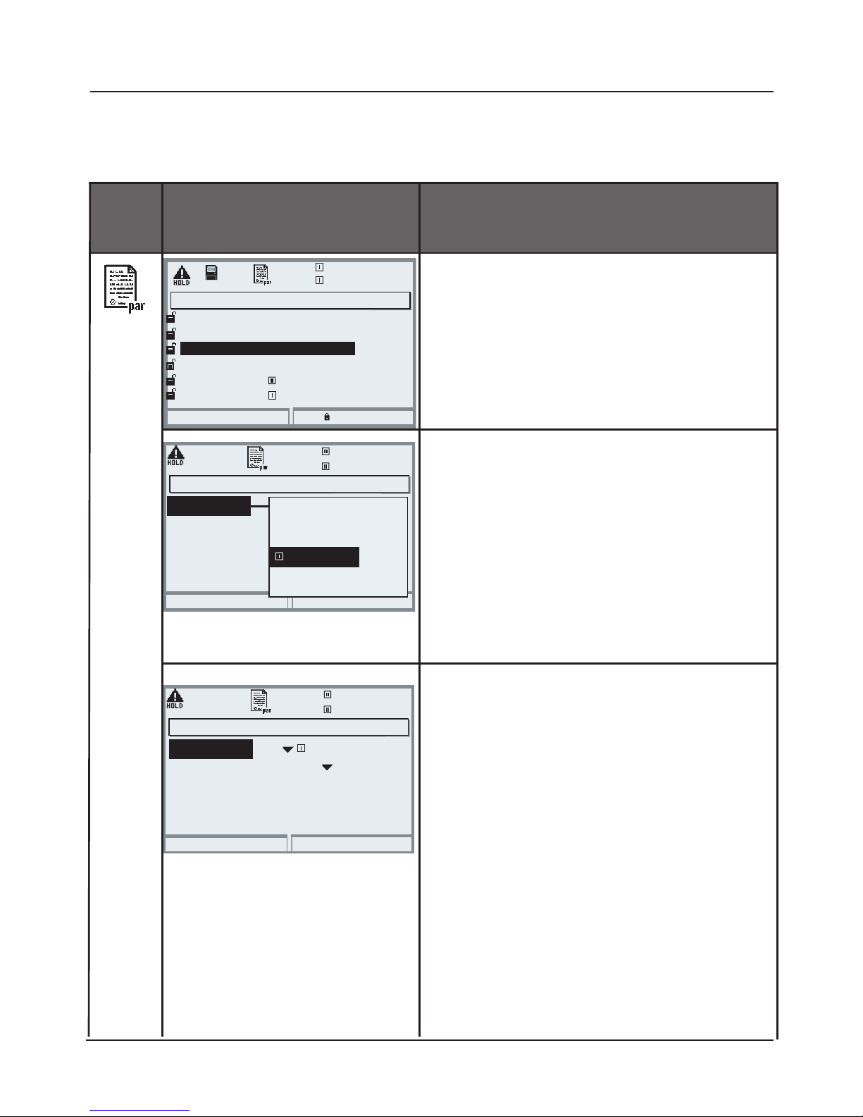
70
Module BASE (Administrator)
Output current I1
Return
Block
7.00 pH
Contact K4
Output current I2
Contact K3
19.0°C
(NAMUR Failure)
Contact K2
Contact K1
(NAMUR maintenance)
( Sensoface)
( Sensoface)
Relay Contacts: Sensoface Messages
Parameter setting/Module BASE/Relay contacts/Usage/Sensoface
Set contact parameters
• (e.g. "N/O")
• Set ON / OFF delay.
Menu
Display Parameter setting (Sensoface)
Relay contacts, usage
• Open parameter setting
• Enter passcode
• Select “Module BASE”
• Select contact e.g. K1)
• Assign Sensoface message of
desired measuring module to
selected relay contact
Contact K1 (Administrator)
19.2°C
Return
Hysteresis
Variable
Limit value
7.00 pH
Usage
Effective direction
Contact type
Limit value
NAMUR maintenance
NAMUR HOLD
Sensoface
Parameter set B active
USP output
Contact K1 (Administrator)
19.2°C
Return
OFF delay
ON delay
7.00pH
Usage
Contact type
0010 s
Sensoface
N/O
0010 s
Assign Sensoface messages to relay
contacts
When more than one measuring
module is used, the Sensoface messages of the modules can be assigned
to different contacts.
Page 71
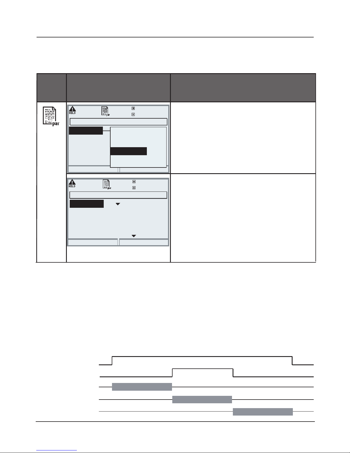
71
Set rinse contact parameters
• Set rinse interval
• Set rinse duration
• During the defined "lead time" the
"HOLD" mode is active.
• Select contact type
(e.g. "N/O")
Rinse Contact
Parameter setting/Module BASE/Relay contacts/Usage/Rinse contact
Menu
Display Configuring the rinse contact
Relay contacts, usage
• Open parameter setting
• Enter passcode
• Select “Module BASE”
• Select contact e.g. K1)
• “Rinse contact” (Fig.)
Contact K1 (Administrator)
19.2°C
Return
Hysteresis
Variable
Limit value
7.00 pH
Usage
Effective direction
Contact type
Limit value
NAMUR maintenance
NAMUR HOLD
Rinse contact
Parameter set B active
USP output
Rinse contact
Contact K1 (Administrator)
19.2°C
Return
Rinse duration
Rinse interval
Rinsing lead time
7.00pH
Usage
Measurement lead time
Contact type
0010 s
Rinse contact
000.0 h
0010 s
N/O
0016 s
Please note when configuring the "Rinse contact" function
• "HOLD" mode (e.g. during parameter setting) delays the execution of the
"Rinse contact" function.
• Up to 3 rinse functions (contacts K1 ... K3) can be configured independently.
• The individual rinse functions are not synchronized with each other.
Time response
HOLD
Contact Kx
Lead time
Rinse duration
Shut-off delay
Page 72
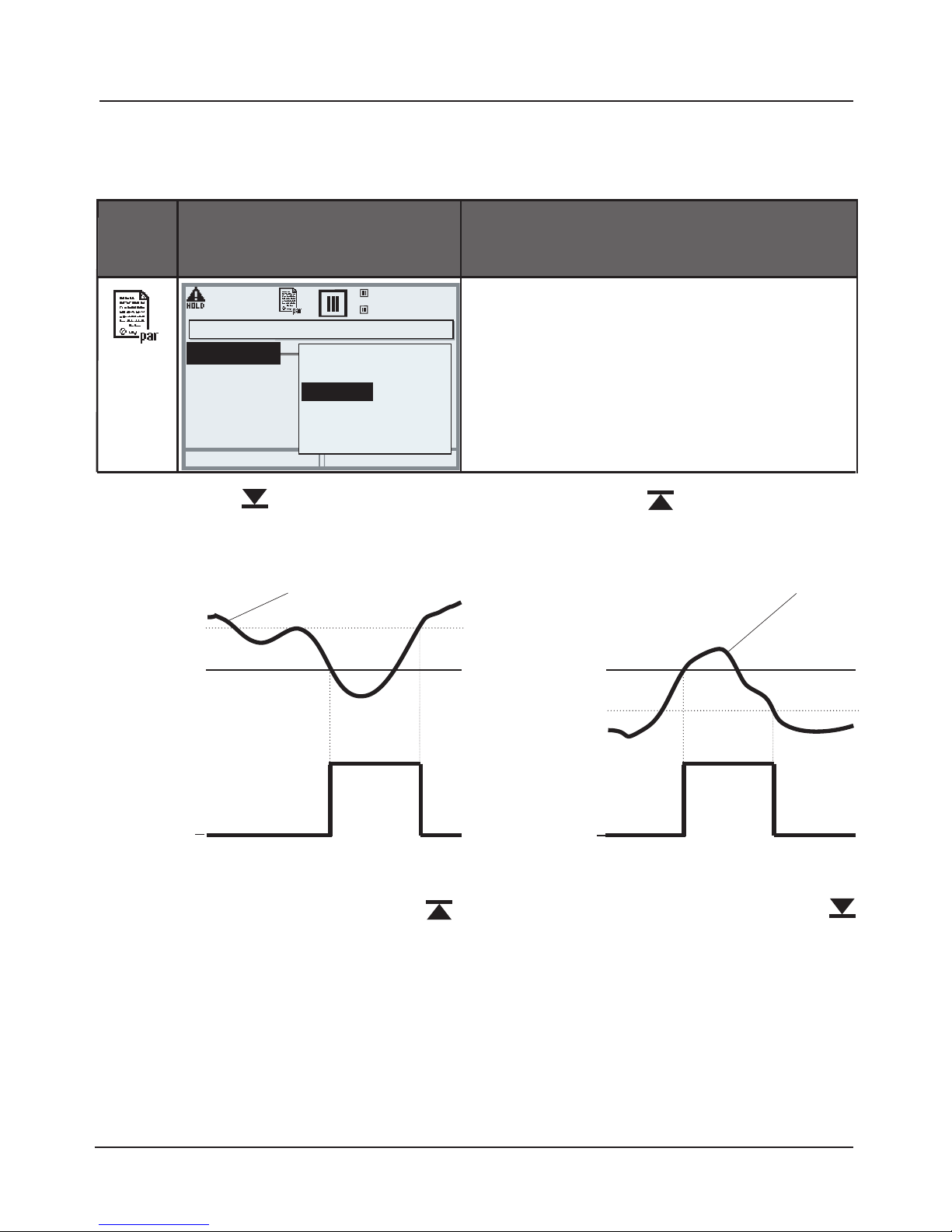
72
Limit Value, Hysteresis, Contact Type
Parameter setting/Module BASE/Relay contacts/Usage
Menu Usage as limit value
Relay output: Limit value
• Open parameter setting
• Enter passcode
• Select “Module BASE”
• Select “Contact ...”
• “Usage: Limit” (Fig.)
Limit value
Effective direction min
Hysteresis +
Limit value
Contact
0
1
Signal
Limit value
Effective direction max
Hysteresis -
Signal
Limit value
Contact
0
1
Contact type
Specifies whether the active contact is closed (N/O) or open (N/C).
Contact K1 (Administrator)
19.2°C
Return
Hysteresis
Variable
Limit value
7.00 pH
Usage
Effective direction
Contact type
Limit value
NAMUR maintenance
NAMUR HOLD
Rinse contact
Parameter set B active
USP output
Hysteresis
Tolerance band around the limit value, within which the contact is not
actuated. Serves to obtain appropriate switching behavior at the output
and suppress slight fluctuations of the measured variable (Fig.)
Icons in the measurement display
Measured value falls below limit:
Measured value exceeds limit:
Limit value
Page 73
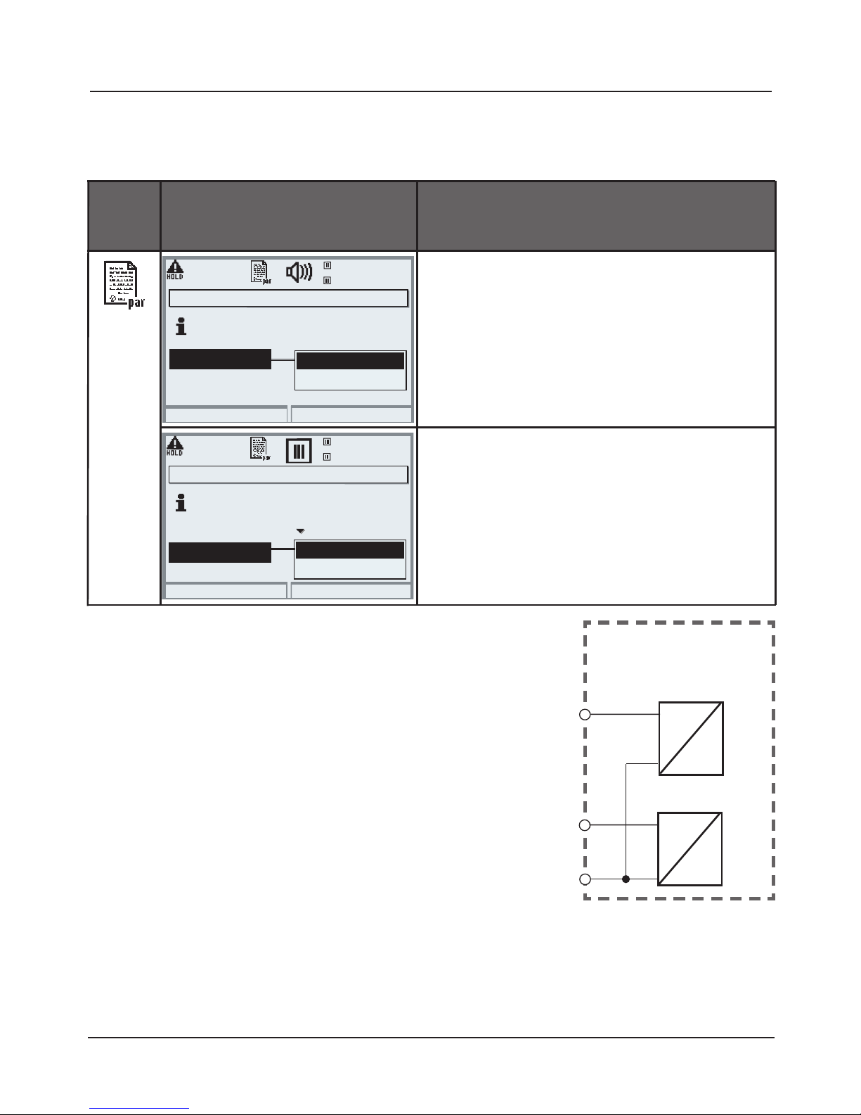
73
OK1, OK2 Inputs: Specify Level
Parameter setting/Module BASE/Inputs OK1, OK2
Note: HOLD mode (Setting: BASE module)
Menu Display Setting the OK inputs
OK1 usage
• Open parameter setting
• Enter passcode
• Select “Module BASE”
• Select “Inputs OK1/OK2”
• Select “OK1 usage”
OK1/OK2 switching level
• Open parameter setting
• Enter passcode
• Select “Module BASE”
• Select “Inputs OK1/OK2”
• Specify active switching level
The BASE module provides 2 digital inputs
(OK1, OK2). The following functions (depending
on the parameter setting) can be started via a
control signal:
• OK1: “Off” or “HOLD”
• OK2: Select: System control / Function
control matrix. (“Off”, “Parameter set A/B”,
“Start KI recorder”)
You must specify the switching level
for the control signal:
(active 10...30 V or active < 2 V).
Module BASE
OK1
OK2
OK1
OK2
OK
Inputs OK1, OK2 (Administrator)
19.2°C
Return
OK2 usage
7.00 pH
OK1 usage
Off
HOLD
For OK2 usage see
“Function control matrix”
Inputs OK1, OK2 (Administrator)
19.2°C
Return
OK1 usage
7.00 pH
Input OK1
active 10 ... 30 V
active < 2 V
For OK2 usage see
“Function control matrix”
HOLD
Input OK2
OK
Page 74
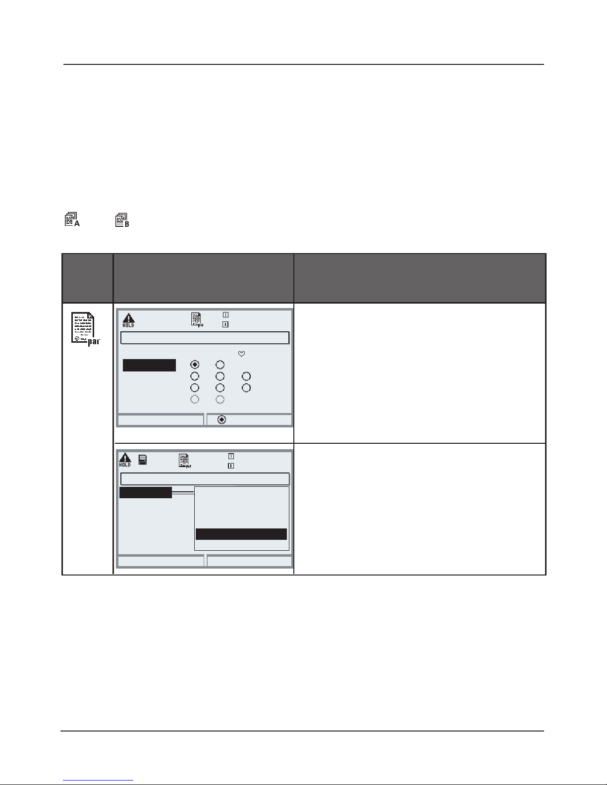
74
Switching Parameter Sets via OK2
Parameter setting / System control / Function control matrix
Note: HOLD mode (Setting: BASE module)
Parameter Sets
2 complete parameter sets (A, B) can be stored in the analyzer.
You can switch between the parameter sets using the OK2 input.
The currently activated set can be signaled by a relay contact.
An icon in the measurement display shows which parameter set is active:
or
Menu Display
Parameter sets
Signaling Active Parameter Set via
Relay Contact
• Open parameter setting
• BASE module
• Select contact
• Usage: “Parameter set ...”.
Select Parameter Set (A, B) via OK2
Input
• Open parameter setting
• System control
• Function control matrix
• Select “OK2”
• Connect “Parameter set A/B”
Contact K3 (Administrator)
Abort
24.8°C
Contact type
OK
NAMUR maintenance!
Usage
ON delay
NAMUR HOLD
Limit value
Rinse contact
Parameter set B active
USP output
83.1 % Air
OFF delay
Note
The selection has no effect when working on SmartMedia card with
SW 3400-102.
24.8°C
Left softkey
83.1 % Air
Return
Connect
Function control matrix (Administrator)
Input OK2
Right softkey
Profibus DO 2
ParSet KI rec. Fav Unical
– –
–
–
––
Page 75
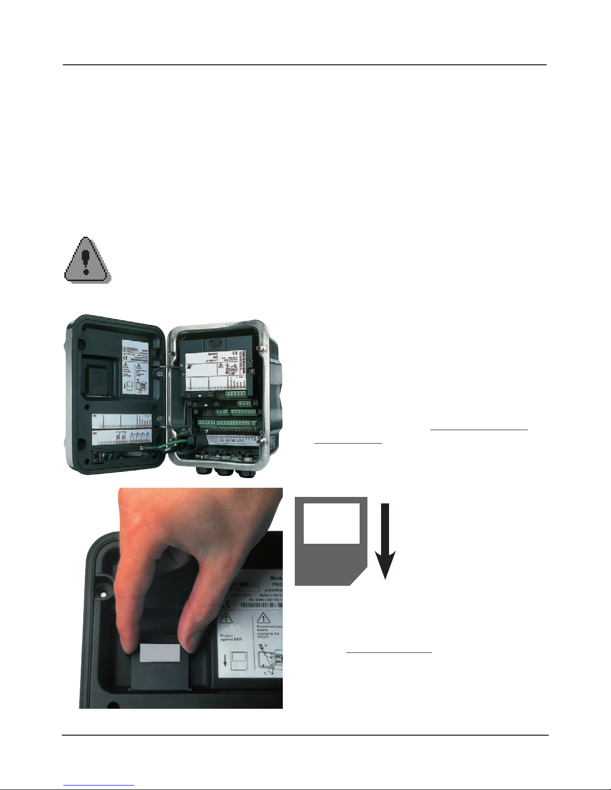
75
Inserting the SmartMedia Card
Please note when inserting the SmartMedia card:
Protect against electrostatic discharge!
The analyzer must be opened to insert or replace the SmartMedia card.
Power can remain on. When closing the device, make sure that the sealing is
properly seated and clean.
Inserting the SmartMedia card
Warning!
Do not touch the terminal compartment, there may be dangerous
contact voltages!
1. Open the analyzer
• Loosen the 4 front screws
• Open the FRONT module at its right side
(pivot hinge inside at the left)
• The slit for inserting the SmartMedia card is
located at the inner side of the FRONT module
2. Insert SmartMedia card
• Remove SmartMedia card without touching the
contact surface from its package
• Insert card in the slit at the inner side of the
FRONT module
Inserting the
SmartMedia card:
The label must be facing
you.
3. Remove SmartMedia card
• To avoid data loss, please open the
Maintenance menu.
• Select “Close memory card” to terminate
software access to the SmartMedia card.
Now the card can be taken out.
Page 76
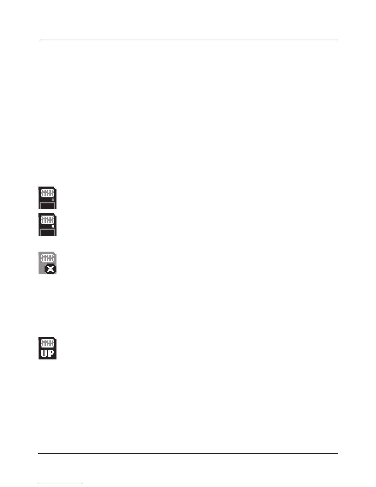
76
SmartMedia Card: Types
SmartMedia card: display icons
When the analyzer has recognized the SmartMedia card, it displays an icon
resembling a SmartMedia card:
Types of SmartMedia cards provided by the manufacturer
The SmartMedia cards are supplied preformatted as:
• Memory Card (SW 3400-102 ... 1xx)
• Software update (SW 3400-106)
Software update card (additional function SW 3400-106)
This SmartMedia card is specially preformatted and allows a software
update. In that case the previous operating program of the analyzer
(“firmware”) will be replaced by a new version.
An update card can also be used to save older versions of the operating program. You cannot save general data on a SmartMedia card of the
type “Update card”. By formatting an update card you can generate a
“memory card” (irreversible!) Formatting erases the update!
Memory card (SW 3400-102 ... 1xx)
This type of card allows the storage of data (e.g. configuration,
parameter sets, logbook, measurement recorder data).
The icon flashes to indicate active data transmission.
SmartMedia card locked against data access
(type “memory card”)
To avoid data loss, a memory card must be “closed” in the
Maintenance menu before it is removed.
The icon shown on the left is displayed.
Now the card can be taken out.
(A locked card can be opened in the Maintenance menu.)
Page 77
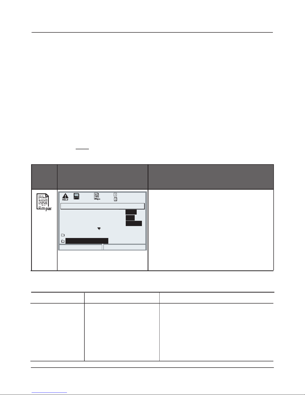
77
SmartMedia Card: Memory Cards
Formatting commercial SmartMedia cards
Commercially available SmartMedia card as memory card.
The following types of cards are supported: 8 MB, 16 MB, 32 MB, 64 MB,
and 128 MB. Externally produced files, such as from a digital camera, are
tolerated. Long file names can be read. The Protos 3400(X) generates file
names in the 8.3 format (8 characters file name, 3 characters program-specific
file name extension).
Formatting a commercial SmartMedia card
Please format a commercial SmartMedia card as Protos memory card before
use. Please do NOT format the card in a PC card reader, always use the Protos!
Menu Display
Formatting commercial SmartMedia
cards
Format
• Insert SmartMedia card
• Open menu selection
• Parameter setting, Admin. level
• Enter passcode
• System control: Memory card
(“Memory card” function only available
with SmartMedia card inserted!)
• Format card
Memory card (Administrator)
Record logbook
Return
20.4 °C
Record recorder
Decimal separator
Format card
Data saving
7.00 pH
Card full
On
On
Point
Record stop
Off
Off
Comma
File structure of a memory card
Folder Typ. file name Remark
BACKUP
LOGBOOK
PARASET
RECORDER
BACKUP01.PAR
L_YYMM00.TXT
SET 1
R_YYMMDD.TXT
BACKUP device configuration
Logbook file,
YY=year, MM= month
Parameter set
Recorder entry,
YY=year, MM=month, DD=day
Formatting SmartMedia cards as memory cards
Page 78

78
Saving / Loading Device Configuration
Parameter setting/System control/Copy configuration
Saving / Loading the complete device configuration
Parameter setting/System control/Memory card/Copy configuration
“Save“ configuration means that the complete device configuration
(except the passcodes) is written on the memory card.
“Load” configuration means that the complete device configuration is read
from the memory card and pogrammmed.
BACKUP file generated on SmartMedia card: \BACKUP\BACKUP01.PAR
Transferring the complete device configuration from one device
to further devices
Prerequisite:
The devices have the same hardware equipment,
the modules are placed in the same slots
(e.g. PH 3400-035 in slot I, COND 3400-041 in slot II etc.).
Options:
All required options must be enabled in the “master device”,
the options in the “slave devices” can be a subset of them.
Only the option parameters are transferred, not the option itself.
When an option is enabled in a “slave device” at a later point in time,
the parameters of this option are already initialized according to the
“master device”.
1) Write device configuration of configured device on SmartMedia card:
Parameter setting/System control/Copy configuration/Save.
2) Change to maintenance menu. Select “Close memory card”.
3) Remove the SmartMedia card. Now you can transfer the device
configuration to further identically equipped devices.
4) To do so, insert the SmartMedia card containing the configuration
in the next device to be configured.
Select
Parameter setting/System control/Copy configuration/Load.
5) Change to maintenance menu. Select “Close memory card”.
6) Remove the SmartMedia card.
Memory card: Copy configuration
Page 79
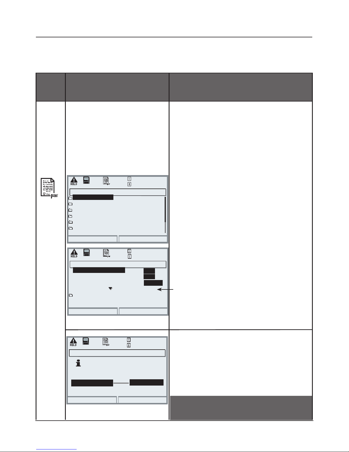
79
Menu Display Using the memory card
To use the memory card
• Insert SmartMedia card
• Open menu selection
• Parameter setting, Admin. level
• Enter passcode
• System control: Memory card
With SmartMedia card inserted, the
display shown on the left appears
(The “Memory card” line is displayed
only if a memory card is in the slot).
• Select “Memory card”,
confirm with enter.
The menu is self-explanatory.
Behavior when the memory card is
full:
Continuous recording
(as with a flight recorder) or
Stop (card replacement).
Copy configuration
• Save: Saving all data on the
memory card
• Load: Overwriting all device data
with the data from the memory
card
Using the Memory Card
Parameter setting/System control/Memory card
Return
25.6 °C
7.00 pH
Copy configuration
Function control matrix
Time/date
Parameter sets
Point of meas description
Memory card
Return
25.6 °C
7.00 pH
Record recorder
Card full
Decimal separator
Format card
Record logbook
On
Point
On
Record stop
Off
Off
Comma
Return
25.6 °C
7.00 pH
Identical module equipment
required for transfer.
Memory card (Administrator)
Copy configuration (Administrator)
Save
Load
Configuration
Save
System control (Administrator)
Caution! “Close” memory card before
removing it (Maintenance menu)
Page 80
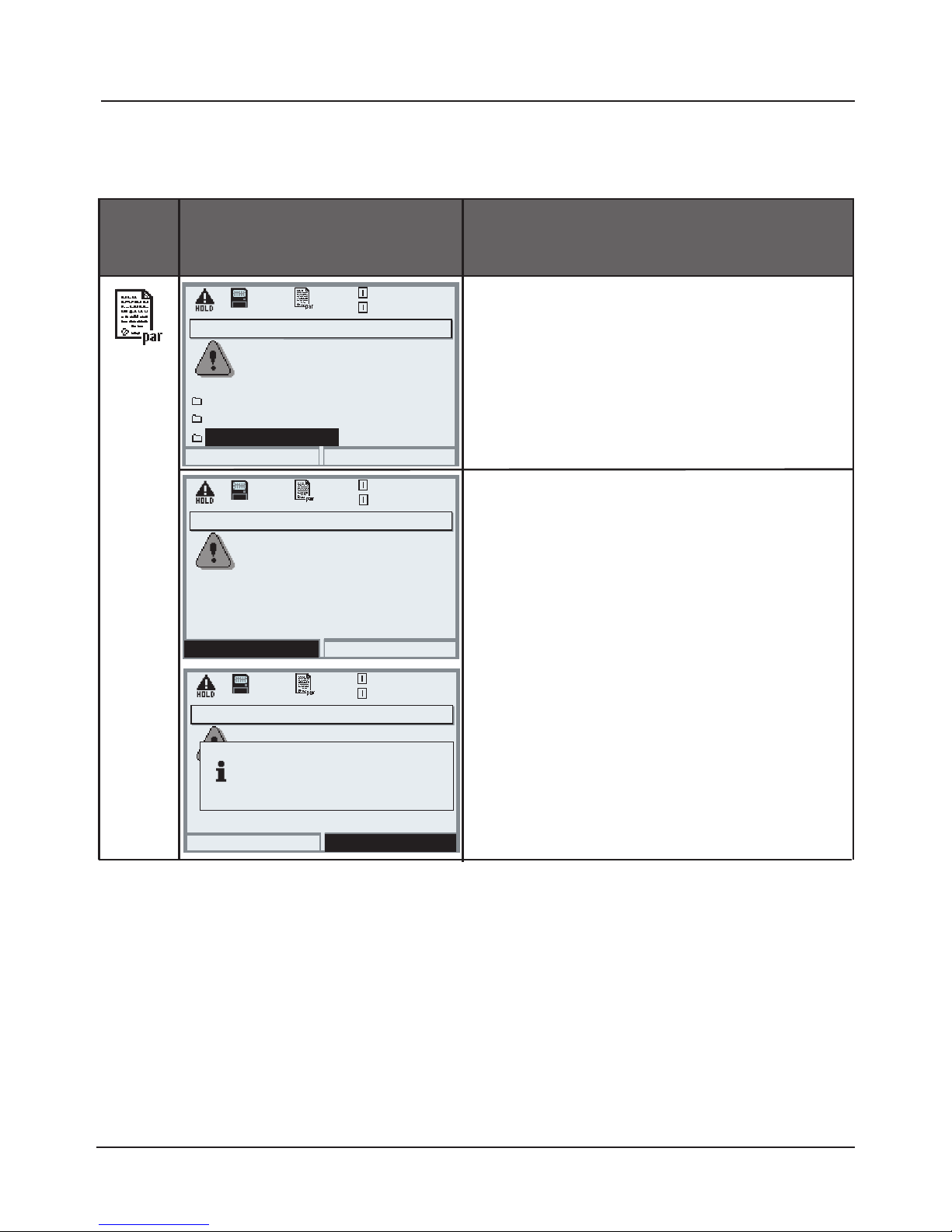
80
Menu Display
Formatting the update card
(generate memory card)
To format the card
• Insert SmartMedia card
• Open menu selection
• Parameter setting, Admin. level
• Enter passcode
• System control: Format card
Formatting an update card generates
a memory card.
Caution! This process is irreversible!
Double warning messages protect
against faulty operation.
When formatting is finished,
a message will be displayed.
Software update (Administrator)
Updating will change the
Return
20.4 °C
device characteristics. Perform
verification as appropriate!
Update firmware
Save firmware
7.00 pH
Formatting the Update Card
Parameter setting/System control/Format card
Note: HOLD mode active
Format card
Format card (Administrator)
Caution: All data on the
Format
20.4 °C
memory card are deleted!
7.00 pH
Return
Format card (Administrator)
20.4 °C
7.00 pH
Close
Formatting ended.
The card can be removed now.
Formatting an update card
Page 81
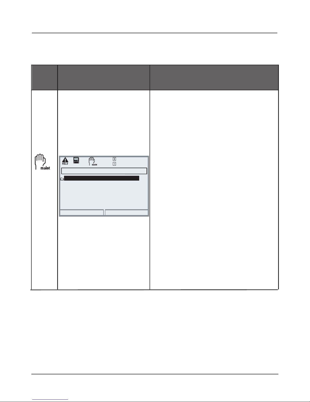
81
Menu Display Close memory card
Remove memory card
• Insert SmartMedia card
• Open menu selection
• Maintenance, Memory card
• “Close card”
Close memory card
terminates software access to the
SmartMedia card. Must be executed
before removing the card from the
SmartMedia card slot to prevent data
loss.
Do not remove the card while the dot
in the SmartMedia card icon flashes!
SmartMedia Card: Remove Card
Maintenance/Removing memory card
Note: HOLD mode active
Return
25.6 °C
7.00 pH
Open/close memory card
Maintenance (Administrator)
Caution!
“Close” memory card before
removing it (Maintenance menu)
Otherwise you risk losing data.
Remove SmartMedia card/Close memory card
Page 82
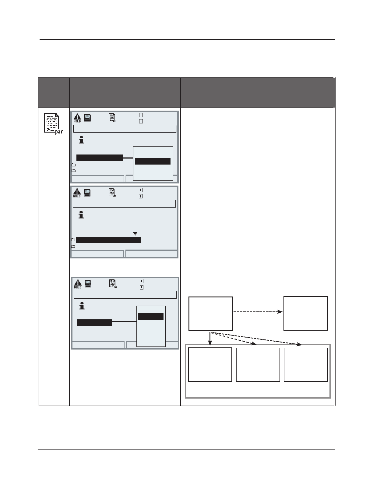
82
SW 3400-102: Loadable Parameter Sets
Parameter setting/System control/Parameter sets
Note: Additional function SW 3400-102 required.
Menu Display
Saving parameter set on
SmartMedia card
To save a parameter set on
SmartMedia card
• Open parameter setting
• System control
• Open “Parameter sets” (Fig)
The analyzer provides 2 complete
parameter sets (A, B).
Up to 5 parameter sets can be loaded
to the SmartMedia card. To do so, a
parameter set (1, 2, 3, 4, or 5) of the
SmartMedia card is overwritten by the
device-internal parameter set A.
• Selecting the parameter set on the
SmartMedia card
Set A
SmartMedia card
Set 1
Set 2 Set 3
Abort
Switchover via softkey
Settings in the menu
Softkey usage
Parameter sets
Save parameter set A
24.2 °C
0.120 mS/cm
Load parameter set A
A,B (internal)
1,2 (card)
1,2,3 (card)
1,2,3,4 (card)
1,2,3,4,5 (card)
Return
Switchover via softkey
Settings in the menu
Softkey usage
Parameter sets
24.2 °C
0.120 mS/cm
1,2,3,4 (card)
Load parameter set A
Save parameter set A
Abort
NOTE: Old parameter set
will be overwritten!
24.2 °C
0.120 mS/cm
Save to
3 (card)
2 (card)
B (internal)
4 (card)
5 (card)
1 (card)
Set B
(internal
only)
Save parameter set A (Administrator)
Parameter sets (Administrator)
Parameter sets (Administrator)
Parameter sets on
SmartMedia card (SW
3400-102)
Parameter set as file on a memory card:
Stored in "PARASET" folder, typical file name "1.SET".
Page 83
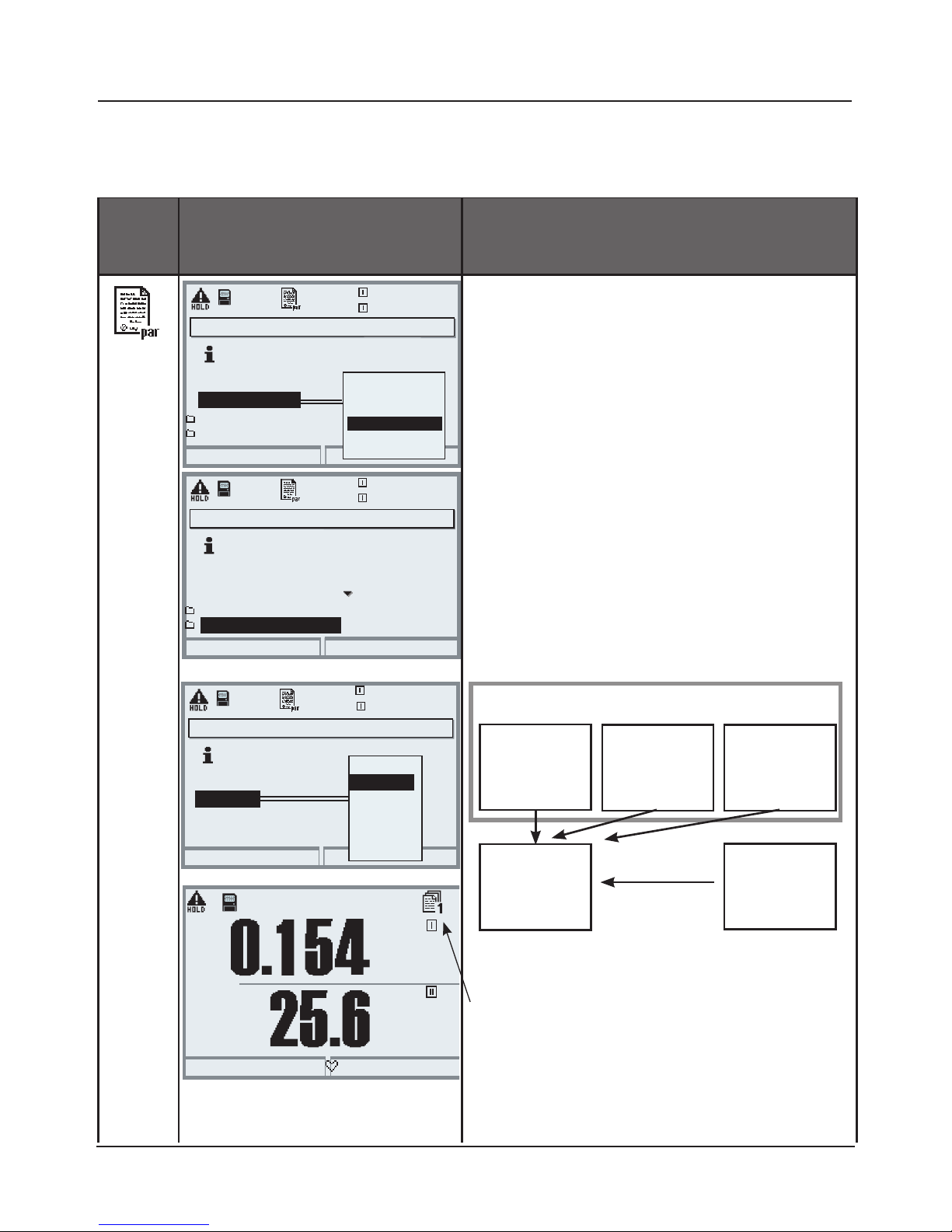
83
Menu Display
Load parameter set from
SmartMedia card
To load a parameter set from
SmartMedia card
• Open parameter setting
• System control
• Open “Parameter sets” (Fig)
The analyzer provides 2 complete
parameter sets (A, B).
5 parameter sets can be stored on the
SmartMedia card.
One of those can be saved as
parameter set A to the analyzer:
• Select parameter set to be loaded.
Activated parameter set is displayed in measuring mode.
Note: Remote switching between A
and B is possible via the OK2 input.
Set 1
Set A
Set 2 Set 3
SmartMedia card
SW 3400-102: Loadable Parameter Sets
Parameter setting/System control/Parameter sets
Parameter sets (Administrator)
Abort
OK
Select with softkey
Settings in menu
Softkey usage
Parameter sets
Save parameter set A
25.1 °C
0.120 mS/cm
Load parameter set A
A,B (internal)
1,2 (card)
1,2 ,3 (card)
1,2,3,4 (card)
1,2,3,4,5 (card)
Parameter sets (Administrator)
Return
Select with softkey
Settings in menu
Softkey usage
Parameter sets
Save parameter set A
25.0 °C
0.120 mS/cm
1,2,3,4 (card)
Load parameter set A
Load parameter set A (Administrator)
Abort
NOTE: Old parameter set
will be overwritten!
24.9 °C
0.120 mS/cm
Load from
3 (card)
2 (card)
B (internal)
4 (card)
5 (card)
1 (card)
mS/cm
°C
Time 11:49
Favorites menu
Set B
(internal
only)
Page 84
84
For a software update (additional function SW 3400-106), the manufacturer
supplies a specially formatted SmartMedia card. The analyzer replaces its own
firmware (operating program) by the new version (“Update”).
Caution!
During a software update the analyzer is not operable!
After a software update you should check the configuration.
2. Load the software update as described on Pg 86.
Notice:
A memory card can be generated by formatting an update card
(irreversible!). See introductory chapter to SmartMedia card.
SW 3400-106: Software Update
This icon indicates that a SmartMedia card is inserted in the slot.
The card allows storing of current device software on the card as well as
loading of new software into the analyzer.
1. Save the firmware currently installed in your analyzer (Pg 85)
Page 85
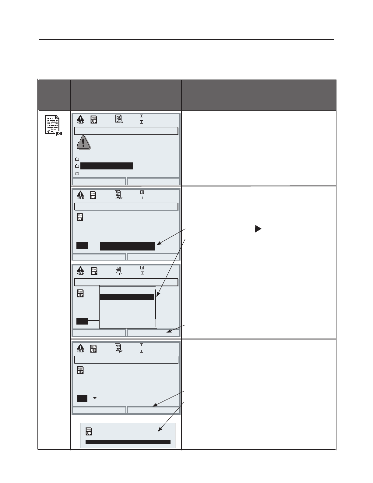
85
Menu Display
Save firmware
on software update card
Save firmware
• Insert SmartMedia card
• Open menu selection
• Parameter setting, Admin. level
• Enter passcode
• System control: Software update
Select a free memory slot
on the card:
• Select slot with key
• Select free slot with arrow keys.
• Confirm slot with “OK”.
Start with “Save” softkey.
Confirm finish message
(with “OK” or enter).
Remove the SmartMedia card.
Close the front door.
Software update (Administrator)
Updating will change the
Return
20.4 °C
device characteristics. Perform
verification as appropriate!
Update firmware
Save firmware (Administrator)
20.4 °C
Save firmware
0.120 mS/cm
0.120 mS/cm
Select a free memory slot
or overwrite a stored
firmware version
Slot
3: <empty>
Return
Save
Save firmware (Administrator)
20.4 °C
0.120 mS/cm
Select a free memory slot
or overwrite a stored
firmware version
Slot
2: SZ34Z10000/0-V6.3
Return
Save
SmartMedia Card: Save Firmware
Parameter setting/System control/Software update/Save firmware
Format card
Save firmware (Administrator)
20.4 °C
0.120 mS/cm
Select a free memory slot
or overwrite a stored
firmware version
Slot
Return
OK
2: SZ34Z10000/0-V6.4
3: <empty>
4: <empty>
5: <empty>
6: <empty>
7: <empty>
Save successful
Page 86
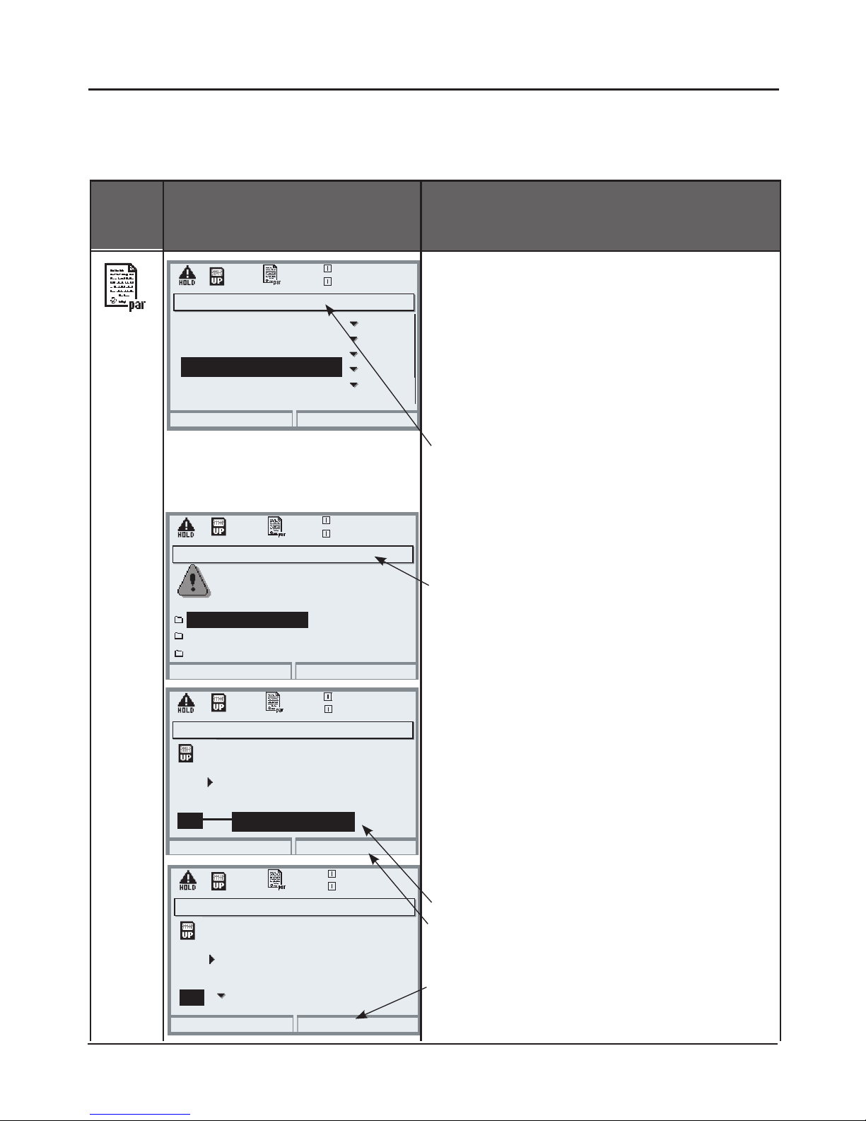
86
Menu
Display
Software update
(“Load firmware”)
Software update (Administrator)
Updating will change the
Return
20.4 °C
device characteristics. Perform
verification as appropriate!
Update firmware
Update firmware (Administrator)
20.4 °C
Save firmware
0.120 mS/cm
0.120 mS/cm
Select the memory slot for
the chosen firmware
indicates the existing version)
Slot
(
1: SZ34Z10000/0-V7.0
Return
Load firmware
Update firmware (Administrator)
20.4 °C
0.120 mS/cm
Select the memory slot for
the chosen firmware
indicates the existing version)
Slot
(
1: SZ34Z10000/0-V7.0
Abort
OK
SmartMedia Card: Load Firmware
Parameter setting/System control/Software update/Load firmware
Format card
Software update
• Insert SmartMedia card
• Open menu selection
• Parameter setting, Admin. level
• Enter passcode
• Select System control
1: Select Release of options
(Software update SW 3400-106)
Set option to “active”. Enter the TAN
at the prompt. The option is available
after the TAN has been entered.
2. Select Software update
Check whether your unit really
requires a software update.
To read the current software version,
select:
• Diagnostics
• Device description
• Module FRONT
Perform update:
• Parameter setting
• System control
• Software update
• Select slot
• Confirm slot with “OK”.
• Press “Load firmware” softkey to
start the software update.
Release of options (Administrator)
Return
25.6 °C
0.120 mS/cm
102 Parameter sets
104 Logbook
103 Measurement recorder
106 Software update
Inactive
Inactive
Inactive
Active
107 AuditTrail
Inactive
Page 87
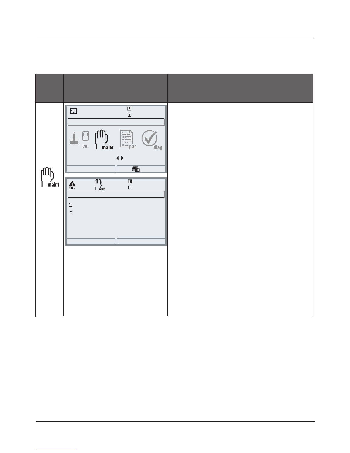
87
Maintenance
BASE Module
Note: HOLD mode active
Menu Display Maintenance
Open Maintenance
From the measuring mode:
Press menu key to select menu.
Select maintenance using arrow keys,
confirm with enter.
Then select "Module BASE".
BASE module: Current source
For testing purposes, the output
current can be manually specified
(range 0 ... 22 mA).
Open/close memory card
terminates software access to the
SmartMedia card. Must be executed
before removing the card from the
SmartMedia card slot to prevent data
loss.
Return to meas
22.3 °C
Select:
[enter]
Lingua
Menu selection
Module BASE 3400-021
Current source
22.3 °C
Return
7.00 pH
7.00 pH
Maintenance
Open/close memory card
BASE module: Current source
Open/close memory card
Page 88
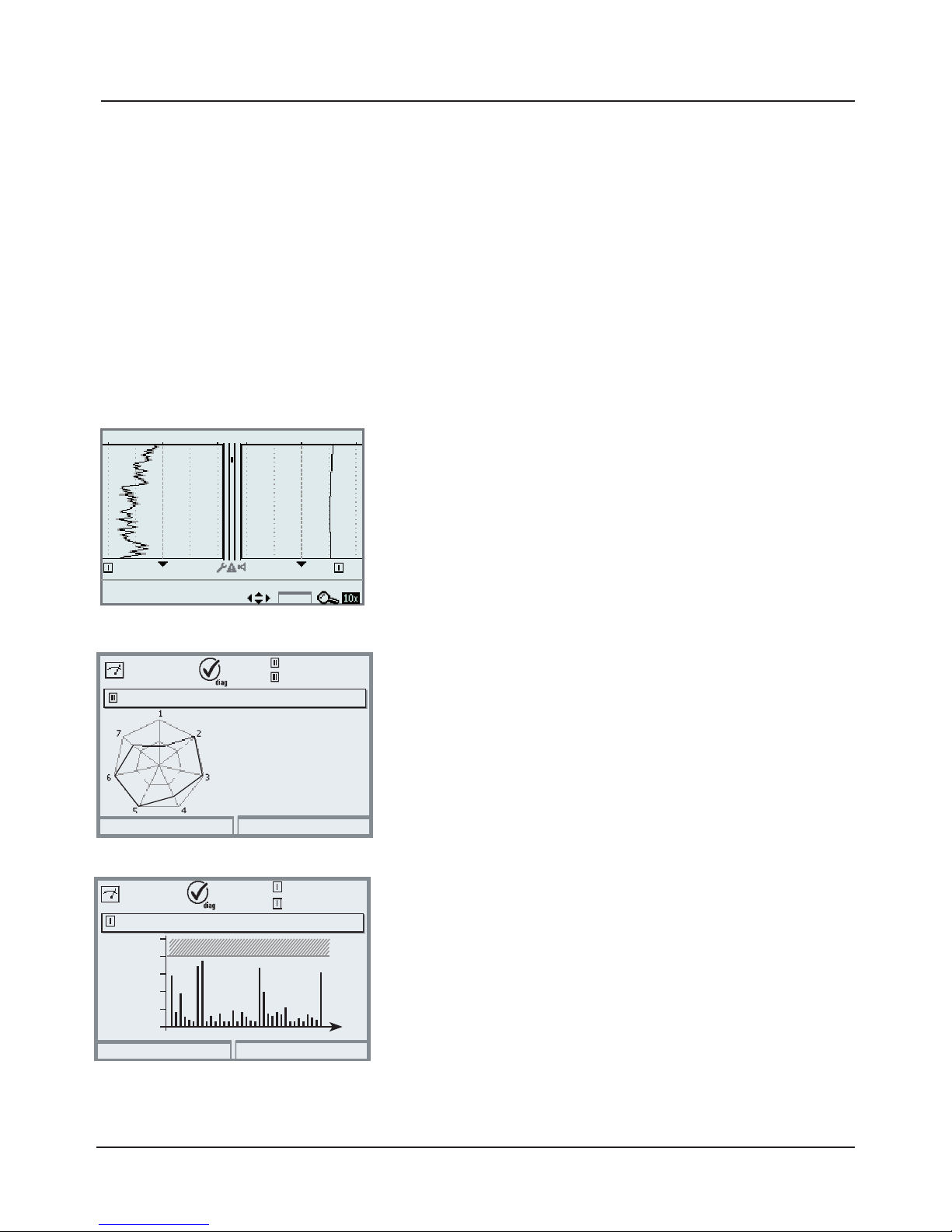
88
Diagnostics Functions
Overview
Selected diagnostics functions for quality management
2-channel measurement recorder
Can be called directly from the measuring mode.
Allows detailed evaluation of events by placing the cursor
on measured values of interest.
S/cm
Info
06/14/06 12:32, Status: Measure
7 pH 25°C
5 pH
°C
0.003 mS/cm, 23.7 °C
1min/pixel
20°C
Diagnostics Functions (Quality Management, ISO 9000 et seq.)
To meet the quality management requirements to ISO 9000, Protos provides
comprehensive diagnostics and safety functions such as Sensocheck sensor
monitoring and CalCheck monitoring of calibration ranges, a logbook for
time- and date-stamped recording of function activations, warning and failure
messages. Further features are:
Sensor network diagram
Return
24.1°C
7.00pH
2 - Zero point
1 - Slope
4 - Glass impedance
3 - Ref impedance
5 - Response time
7 - Calcheck
6 - Cal timer
Info
Sensor network diagram
(PH, OXY modules)
Graphical representation of the sensor parameters in a
network diagram – with slope, zero, reference impedance, glass impedance, response time, calibration timer,
deviation from calibration range.
ServiceScope
(PH module)
Displays the noise levels over the time. Allows distinction
of individual disturbances, periodic and broadband disturbances, which is helpful for troubleshooting. An error
message is generated if the noise level exceeds the failure
limit.
ServiceScope
0.2 °C
Return
Fail
Noise level
7.00pH
t
Diagnostics functions
Page 89
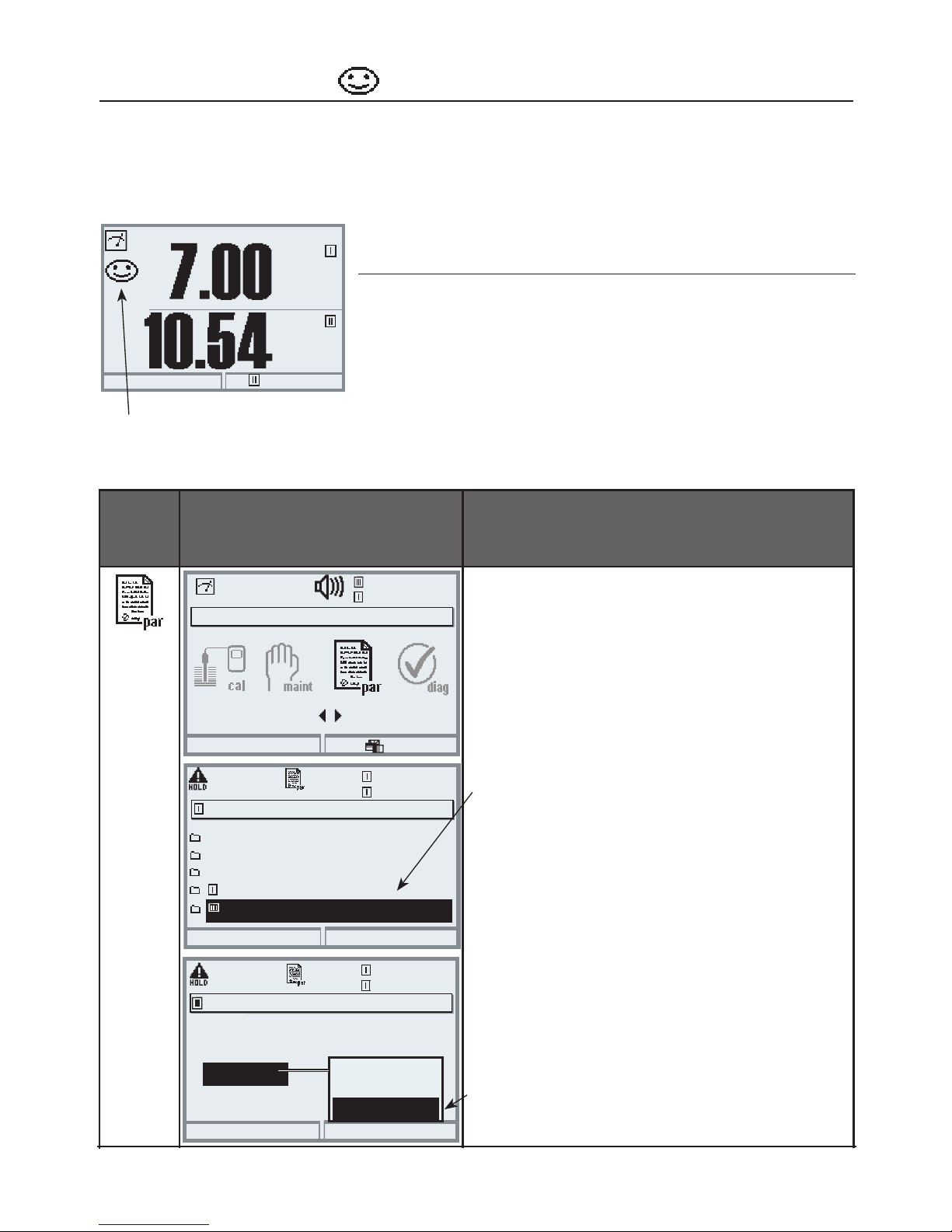
89
Sensoface
Sensoface is a graphical indication of the sensor condition –
Sensocheck must have been activated during parameter setting.
Menu Display Activate Sensocheck
Sensocheck messages can be assigned
to a relay contact
(Parameter setting / Module BASE /
Contact / Usage)
Select parameter setting
Enter passcode (Administrator)
Select measuring module
(e.g. “PH” or “OXY”).
Confirm with enter
Select “Sensor data”.
Confirm with enter.
Then select “Sensocheck Ref el”.
Assign function and confirm with
enter.
Menu selection
Return to meas
Select:
[enter]
Lingua
7.00 pH
25.6°C
25.6°C
Return
7.00 pH
Parameter setting (Administrator)
System control
Module FRONT 3400-011
Module BASE 3400-021
Module PH 3400-032
Module PH 3400-032
25.6°C
Abort
7.00 pH
Sensocheck Ref el (Administrator)
Nominal
Min
Max
Message
005.0 kOhm
003.1 kOhm
100.0 kohms
Maint. request
Off
Failure
pH
pH
24.3°C
Sensocheck - Sensor monitoring
Module Sensocheck function
OXY: Monitoring membrane/electrolyte
COND(I): Information on sensor condition
PH/ORP/
CO
2
:
Automatic monitoring of glass and
reference electrode
The “smileys” provide information on wear and required maintenance of the
sensor (“friendly” - “neutral” - “sad”).
OK
Page 90
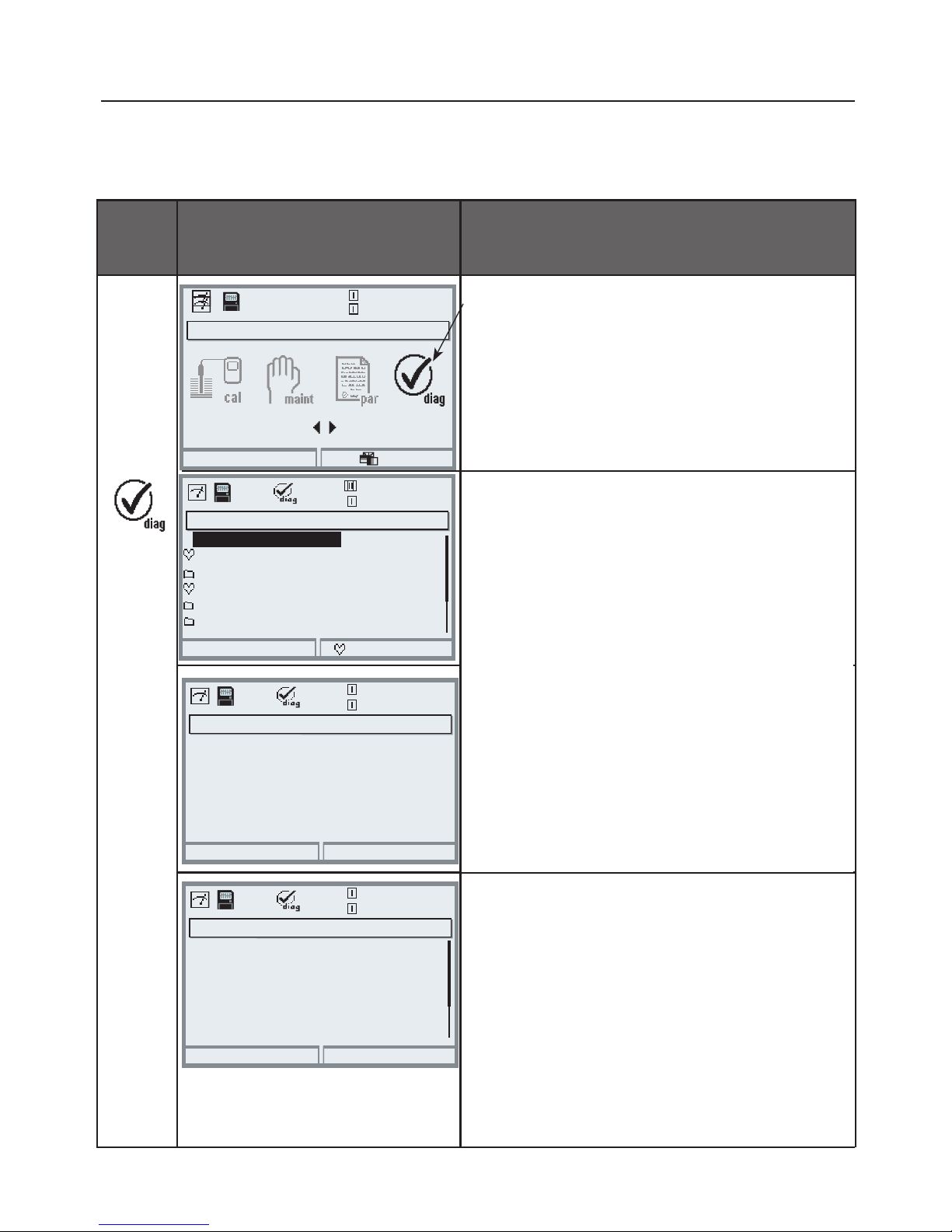
90
Menu
Display Diagnostics functions
Access Diagnostics
From the measuring mode:
Press menu key to select menu.
Select Diagnostics using arrow keys,
confirm with enter.
The “Diagnostics” menu gives an
overview of all functions available.
Functions which have been set as
“Favorite” can be directly accessed
from the measuring mode.
Diagnostics Functions
General status information of the measuring system
Select menu: Diagnostics - Logbook
Logbook
Shows the last 50 events with date and
time, e.g. calibrations, warning and
failure messages, power failure etc.
This permits quality management
documentation to ISO 9000 et seq.
Extended logbook: SmartMedia card
(SW 3400-104)
Menu selection
Return to meas
7.00 pH
25.6°C
Select:
[enter]
Lingua
Diagnostics
Return
25.6°C
Set favorite
7.00 pH
Logbook
Message list
Device description
Module FRONT
Module BASE
Logbook
Return
25.6°C
7.00 pH
03/11/10 15:00 Diagnostics active
03/11/10 09:50 Parameter setting active
03/11/10 10:05 Measurement active
03/10/10 14:33 Measurement active
03/11/10 09:42 Wrong passcode
03/10/10 14:11 Parameter setting active
Logbook
Point of meas description
Return
25.6°C
7.00 pH
Note:
Tank_2
Measurement point
Point of meas description
Allows entering a tag number and a
note. Select position: left/right arrow
key, select character: up/down arrow
key. Confirm the entry with enter.
04/03/2007 smith
Point of meas description
Point of meas description
Logbook
Page 91

91
Additional Function SW 3400-104: Extended Logbook
The extended logbook saves all entries in a file. The last 50 entries can be
displayed on the Protos. A new file is generated for each month. The date is
encoded in the file name.
Example for a file generated on SmartMedia card:
\LOGBOOK\L_YYMM00.TXT Recorder data of YYMM
(YY = year, MM = month)
The data is recorded as ASCII file with the extension .TXT.
The individual columns are separated by tabs. This makes the file readable with
word processing or spreadsheet programs (e.g. Microsoft Excel). E
ach time the memory card is inserted in the slot, a “Device Info” consisting of
Model number, BASE serial number, and tag number is written. Thus, a memory
card can also be used to collect the logbook data of several devices.
Example:
SW 3400-104: Extended Logbook
Parameter setting/System control/Logbook
PROTOS 3400 - Logbook
No. Time Stamp Status Message
<< Protos 3400 - Serial 0001760 [DSE KL_001] >>
F226 21.04.10 19:08:43 Power supply Off
F227 22.04.10 06:02:01 Power supply On
F223 22.04.10 06:09:27 Diagnostics active
F225 22.04.10 06:09:36 Measurement active
B077 23.04.10 16:45:07 (x) Fail current I2 > 20 mA
F222 23.04.10 18:43:11 Parameter setting active
F225 23.04.10 18:47:38 Measurement active
B077 23.04.10 18:47:38 ( ) Fail current I2 > 20 mA
No. Message identifier
Time stamp: Time stamp of logbook entry
Status (x) - Message activated
( ) - Message deactivated
Message Message text (in selected operator language)
Page 92
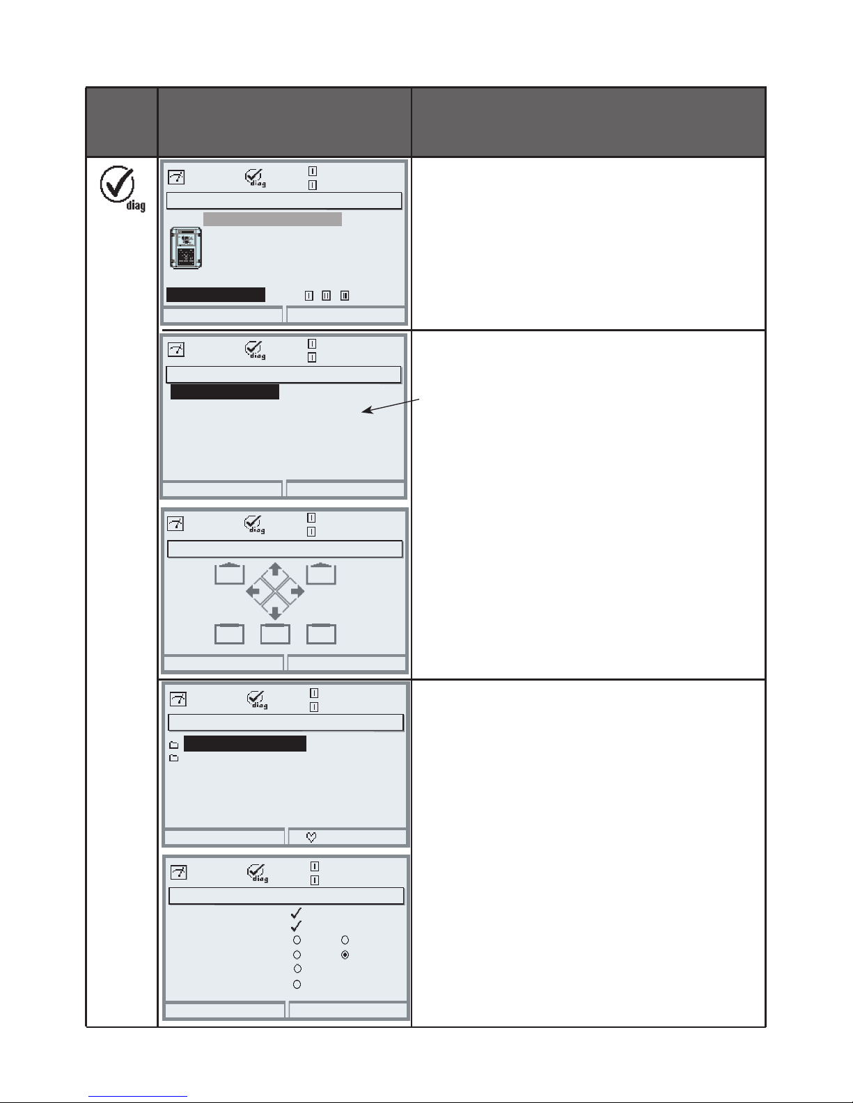
92
Menu Display Diagnostics functions
Device description
Provides information about all
modules installed: Module type and
function, serial number, hardware and
software version and device options
(Example: FRONT).
FRONT module
The module contains the display and
keypad control. Test possibilities:
• Module diagnostics
• Display test
• Keypad test
Example:
Module FRONT, Keypad test.
Correct functioning of each key can be
checked by pressing it down.
BASE module
The module generates the standard
output signals. Test possibilities:
• Module diagnostics
• Input/output status
Example:
Module BASE, input/output status.
Device description
Return
25.6°C
7.00 pH
Operating panel
Module FRONT 3400-011
Hardware: 1, Software: 9.0
Serial number 0000815
BASE
Module
FRONT
Module FRONT
Return
25.6°C
7.00 pH
Display test
Keypad test
Module diagnostics
Keypad test
Return (2x)
25.6°C
7.00 pH
Module BASE
Return
25.6°C
7.00 pH
Input/output status
Set favorite
Module diagnostics
Input/output status
Return
25.6°C
7.00 pH
Current load I1
K1
Current load I2
ok
Contact
Input OK1
ok
Input OK2
K3
Inactive
Inactive
K2
K4
Device description
FRONT module
BASE module
Page 93
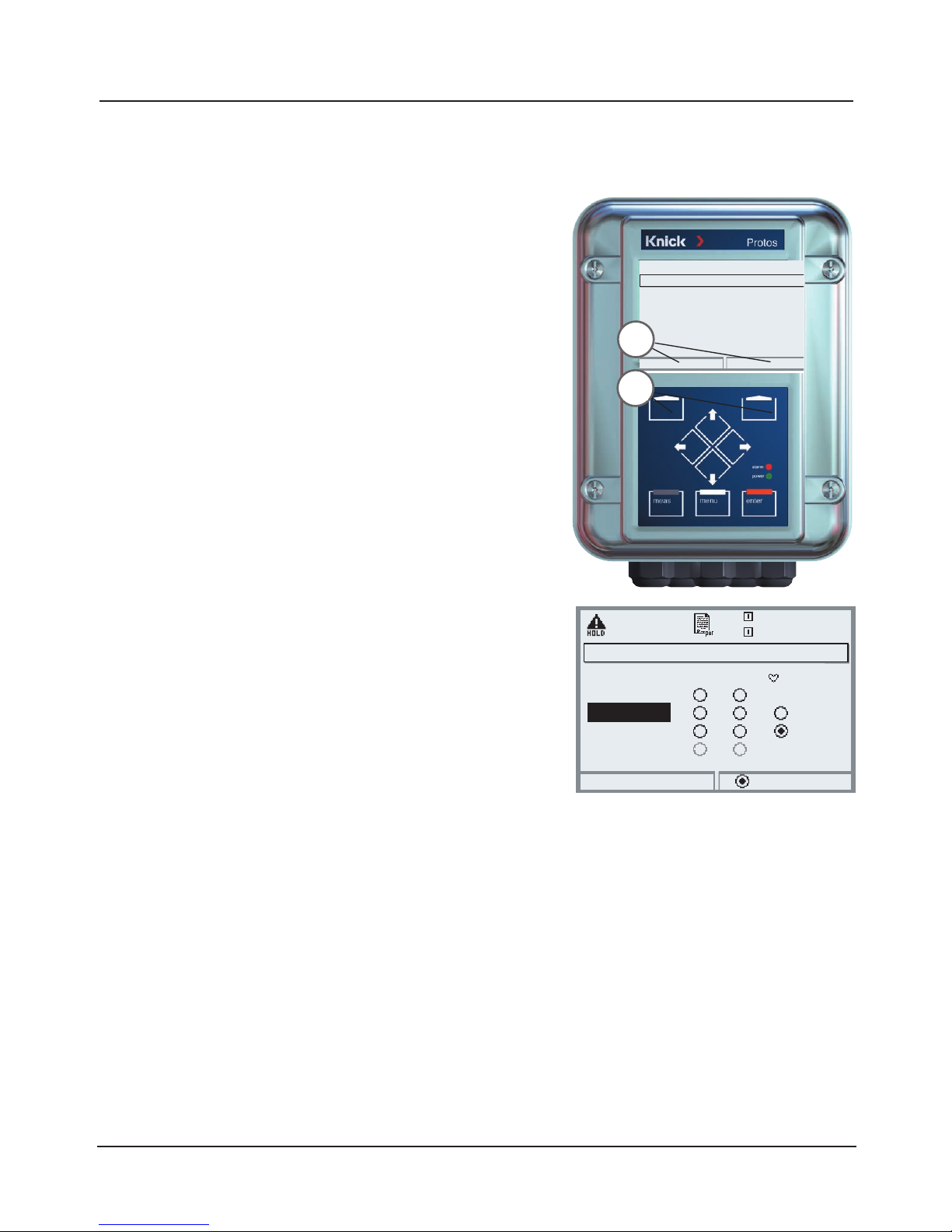
93
Setting Diagnostics Messages as Favorite
Select menu: Parameter setting/System control/Function control matrix
Example:
“Favorites” to be selected with
“Right softkey”
To select a softkey function:
Select desired function using arrow
keys,
press “Connect” softkey and c
onfirm with enter.
To deselect a function:
Press “Disconnect” softkey,
confirm with enter.
1
2
25.6 °C
Input OK2
7.00 pH
Return
Connect
Function control matrix (Administrator)
Left softkey
Right softkey
Profibus DO 2
ParSet KI rec. Fav Unical
– –
–
–
––
Favorites
Selected Diagnostics functions can be called
directly from the measuring mode using a
softkey.
The table on the next page explains how to
select favorites.
Secondary displays (1)
Here, additional values are displayed in the
measuring mode according to the factory
setting. When the respective softkey (2) is
pressed, the process variables measured by
the modules plus date or time are displayed.
In addition, you can use the softkeys (2) to
control functions. To assign a function to a
softkey, select
Parameter setting/System control/
Function control matrix
Function which can be controlled by softkeys:
• Parameter set selection
• KI recorder Start/Stop
• Favorites
• Unical (fully automated probe controller)
Setting diagnostics messages as favorite
Page 94
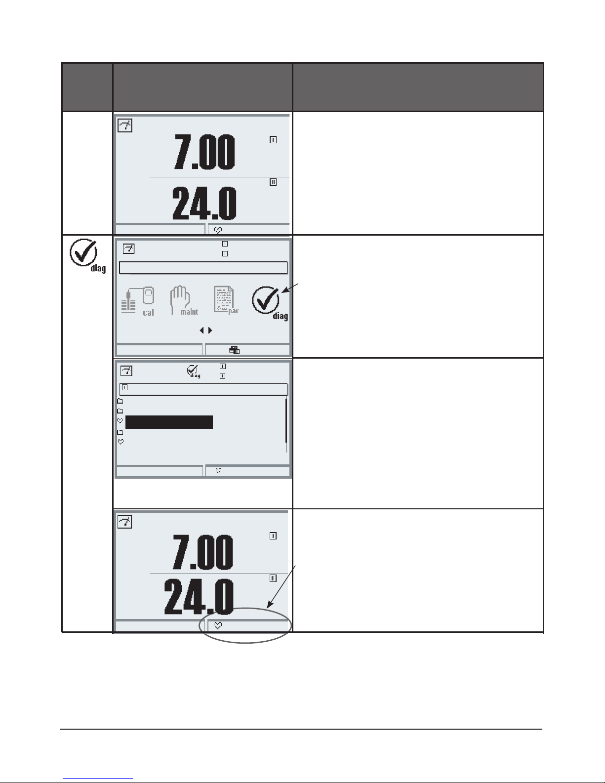
94
Set/delete favorite:
“Set favorite” allows activation of the
selected diagnostic function directly
from the measuring mode via softkey.
The menu line is marked with a heart
icon.
Pressing the meas key returns to
measurement. When the softkey has
been assigned to “Favorites”, “Favorites
menu” is read in the secondary display
(see “Function control matrix”).
Notice:
When one of the softkeys has been assigned to the “Favorites menu” function,
diagnostic functions which have been set as “Favorite” can be directly called
from the measuring mode.
Menu Display Select favorites
Favorites menu
Diagnostics functions can be called
directly from the measuring mode
using a softkey.
The “Favorites” are selected in the
Diagnostics menu.
Select favorites
Press menu key to select menu.
Select diagnostics using arrow keys,
confirm with enter. Then select
module and confirm with enter.
09.03.10
Favorites menu
°C
09.03.10
Favorites menu
Menu selection
Return to meas
7.00 pH
25.6 °C
Select:
[enter]
Lingua
Return
25.6 °C
Set favorite
7.00 pH
Sensor monitor
Cal record
Sensor network diagram pH
Statistics
Module diagnostics
Module PH 3400-032
pH
°C
pH
Page 95
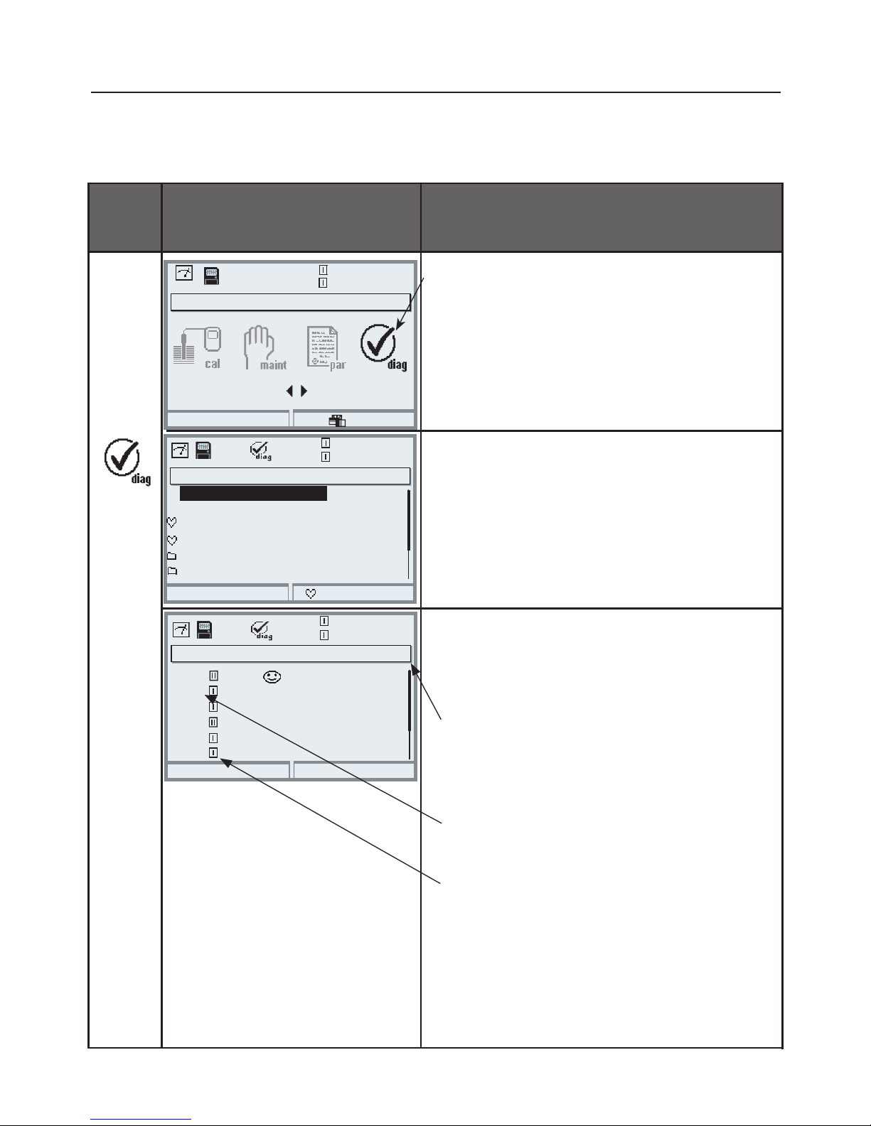
95
Menu
Display Diagnostics functions
Opening the diagnostics menu
From the measuring mode:
Press menu key to select menu.
Select diagnostics using arrow keys,
confirm by pressing enter.
The “Diagnostics” menu gives an
overview of all functions available.
Functions which have been set as
“Favorite” can be directly accessed
from the measuring mode.
Diagnostics Functions
General status information of the measuring system
Select menu: Diagnostics - Message list
Message list
Shows the currently activated warning
or failure messages in plain text.
Menu selection
Return to meas
7.00 pH
25.6°C
Select:
[enter]
Lingua
Diagnostics
Return
23.7 °C
Set favorite
7.00 pH
Logbook
Message list
Device description
Module FRONT
Message list
Return
25.6°C
7.00 pH
Warn
Module BASE
8 messg.
Message list
Point of meas description
Warn Temp Alarm HI
Saturation %Air Alarm HI
Fail Wrong sensor
Warn Tolerance band
Warn Zero Range
D062
P018
D013
P210
P030
Sensocheck
P092
Number of messages
When there are more than 7 messages,
a vertical scrollbar appears.
Scroll with the up/down arrow keys.
Module identifier
Specifies the module that has generated the
message.
Message identifier
See message list for description.
Page 96

96
Messages
Module FRONT 3400-011
Module FRONT 3400(X)-015
No. FRONT messages Message type
F008 Meas. processing (factory settings) FAIL
F009 Module failure (Firmware Flash check sum) FAIL
F060 KI process window exceeded (acknowledgeable message) User-defined
F061 KI recorder parameter WARN
F080 ComFu®-E Channel 1 – [1] No sensor
F081 ComFu®-E Channel 1 – [2] No sensor
F082 ComFu®-E Channel 1 – [1] Communication interrupted
F083 ComFu®-E Channel 1 – [2] Communication interrupted
F084 ComFu®-E Channel 1 – [1] Sensor connection
F085 ComFu®-E Channel 1 – [2] Sensor connection
F086 ComFu®-E Channel 1 – [1] Battery empty
F087 ComFu®-E Channel 1 – [2] Battery empty
F090 ComFu®-E Channel 2 – [2] No sensor
F091 ComFu®-E Channel 2 – [3] No sensor
F092 ComFu®-E Channel 2 – [2] Communication interrupted
F093 ComFu®-E Channel 2 – [3] Communication interrupted
F094 ComFu®-E Channel 2 – [2] Sensor connection
F095 ComFu®-E Channel 2 – [3] Sensor connection
F096 ComFu®-E Channel 2 – [2] Battery empty
F097 ComFu®-E Channel 2 – [3] Battery empty
F200 CRC error PAR FAIL
F201 Communications error (system bus) FAIL
F202 System failure FAIL
F210 Device diagnostics (Self test signals error) WARN
F211 Card error (SmartMedia) WARN
F212 Time/date WARN
F213 Module temperature (range exceeded) WARN
F215 Memory card full WARN
Page 97

97
Messages
No. FRONT messages Message type
F216 AuditTrail card FAIL
F220 Calibration active Text
F221 Maintenance active Text
F222 Parameter setting active Text
F223 Diagnostics active Tex t
F225 Measurement active Text
F226 Power supply OFF Text
F227 Power supply ON Text
F228 Software update Text
F229 Wrong passcode Te xt
F230 Factory setting Text
F231 Module configuration changed Text
F232 Module equipment Ex/non-Ex FAIL
F233 Module equipment Ex FAIL
Page 98
98
Messages
BASE 3400-021 Module
BASE 3400(X)-025/VPW Module
BASE 3400(X)-026/24V Module
No. BASE messages Message type
B008 Meas. processing (factory settings) FAIL
B009 Module failure (Firmware Flash check sum) FAIL
B070 Current I1 Span WARN
B071 Current I1 <0/4 mA WARN
B072 Current I1 > 20 mA WARN
B073 Current I1 Load FAIL
B074 Current I1 Parameter WARN
B075 Current I2 Span WARN
B076 Current I2 <0/4 mA WARN
B077 Current I2 > 20 mA WARN
B078 Current I2 Load FAIL
B079 Current I2 Parameter WARN
B200 Rinsing program active Text
B254 Module reset Text
Page 99
99
Messages
PH 3400-031 Module
PH 3400(X)-032, PH 3400(X)-033, PH 3400(X)-035 Modules
PHU 3400(X)-110 Module
No. PH messages Message type
P008 Meas. processing (factory settings) FAIL
P009 Module failure (Firmware Flash check sum) FAIL
P010 pH Range FAIL
P011 pH Alarm LO_LO FAIL
P012 pH Alarm LO WARN
P013 pH Alarm HI WARN
P014 pH Alarm HI_HI FAIL
P015 Temperature Range FAIL
P016 Temperature Alarm LO_LO FAIL
P017 Temperature Alarm LO WARN
P018 Temperature Alarm HI WARN
P019 Temperature Alarm HI_HI FAIL
P020 ORP Range FAIL
P021 ORP Alarm LO_LO FAIL
P022 ORP Alarm LO WARN
P023 ORP Alarm HI WARN
P024 ORP Alarm HI_HI FAIL
P025 rH Range WARN
P026 rH Alarm LO_LO FAIL
P027 rH Alarm LO WARN
P028 rH Alarm HI WARN
P029 rH Alarm HI_HI FAIL
P030 Zero Range WARN
P035 Slope Range WARN
P040 Isotherm potential Uis Range WARN
P045 mV Range WARN
P046 mV Alarm LO_LO FAIL
Page 100

100
No. PH messages Message type
P047 mV Alarm LO WARN
P048 mV Alarm HI WARN
P049 mV Alarm HI_HI FAIL
P050 Temperature - manual FAIL
P060 SAD SENSOFACE: Slope User-defined
P061 SAD SENSOFACE: Zero User-defined
P062 SAD SENSOFACE: Ref impedance (Sensocheck) User-defined
P063 SAD SENSOFACE: Glass impedance (Sensocheck) User-defined
P064 SAD SENSOFACE: Response time User-defined
P065 SAD SENSOFACE: Cal timer WARN
P066 SAD SENSOFACE: Calcheck User-defined
P069 SAD SENSOFACE: Calimatic (Zero/slope) WARN
P070 SAD SENSOFACE: Sensor wear User-defined
P071 SAD SENSOFACE: ISFET leakage current User-defined
P090 Buffer offset (buffer table to be entered): WARN
P091 Zero offset ORP WARN
P092 Tolerance band WARN
P110 CIP counter User-defined
P111 SIP counter User-defined
P112 Autoclaving counter User-defined
P113 Sensor operating time (duration of use) User-defined
P114 ISFET characteristic User-defined
P115 Membrane body changes User-defined
P120 Wrong sensor FAIL
P121 Sensor (error in factory settings/characteristics) FAIL
P122 Sensor memory (error in cal data records) WARN
P123 New sensor, adjustment required WARN
P130 SIP cycle counted Text
P131 CIP cycle counted Text
P200 Noise level at pH input FAIL
P201 Cal temp WARN
Messages
 Loading...