

Page 1

Instruction Manual
765 Laboratory pH Meter
Page 2

TA-167.000-KNE04 051009 Software version: 4.x
Subject to change without notice
Elektronische Meßgeräte
GmbH & Co.
P.O.Box 37 04 15
D-14134 Berlin
Germany
Tel: +49 (0) 30-80191-0
Fax: +49 (0) 30-80191-200
www.knick.de
[email protected]
Warranty
Defects occurring within 3 years from delivery
date shall be remedied free of charge at our
works (carriage and insurance paid by sender).
Accessories: 1 year
Page 3

The 765 Laboratory pH Meter I
Contents
Information on this instruction manual . . . . . . . . . . . . . . . . . . . . . . . . . . . . . . . . . . . . . . II
Safety information . . . . . . . . . . . . . . . . . . . . . . . . . . . . . . . . . . . . . . . . . . . . . . . . . . . . . . III
EC Declaration of Conformity . . . . . . . . . . . . . . . . . . . . . . . . . . . . . . . . . . . . . . . . . . . . . IV
1 The 765 Laboratory pH Meter
Package contents . . . . . . . . . . . . . . . . . . . . . . . . . . . . . . . . . . . . . . . . . . . . . . . . . . . .1
Short device description . . . . . . . . . . . . . . . . . . . . . . . . . . . . . . . . . . . . . . . . . . . . . . . 1
2 Operation . . . . . . . . . . . . . . . . . . . . . . . . . . . . . . . . . . . . . . . . . . . . . . . . . . . . . . . . . . . . 2
Meter design . . . . . . . . . . . . . . . . . . . . . . . . . . . . . . . . . . . . . . . . . . . . . . . . . . . . . . . . 2
General information . . . . . . . . . . . . . . . . . . . . . . . . . . . . . . . . . . . . . . . . . . . . . . . . . . .3
Power-on and start-up . . . . . . . . . . . . . . . . . . . . . . . . . . . . . . . . . . . . . . . . . . . . . . . . .6
Parameter level . . . . . . . . . . . . . . . . . . . . . . . . . . . . . . . . . . . . . . . . . . . . . . . . . . . . . 10
Calibration level . . . . . . . . . . . . . . . . . . . . . . . . . . . . . . . . . . . . . . . . . . . . . . . . . . . .18
Diagnostics level . . . . . . . . . . . . . . . . . . . . . . . . . . . . . . . . . . . . . . . . . . . . . . . . . . . . 21
Trueline
®
recorder output . . . . . . . . . . . . . . . . . . . . . . . . . . . . . . . . . . . . . . . . . . . . . 30
Serial interface . . . . . . . . . . . . . . . . . . . . . . . . . . . . . . . . . . . . . . . . . . . . . . . . . . . . . . 31
Standard settings for ZU 0244 Lab Printer . . . . . . . . . . . . . . . . . . . . . . . . . . . . . . . .32
Command set for the serial interface. . . . . . . . . . . . . . . . . . . . . . . . . . . . . . . . . . . . . 32
3 Troubleshooting . . . . . . . . . . . . . . . . . . . . . . . . . . . . . . . . . . . . . . . . . . . . . . . . . . . . . . 41
Error messages . . . . . . . . . . . . . . . . . . . . . . . . . . . . . . . . . . . . . . . . . . . . . . . . . . . . . 41
Appendix . . . . . . . . . . . . . . . . . . . . . . . . . . . . . . . . . . . . . . . . . . . . . . . . . . . . . . . . . . . . . 45
Product line . . . . . . . . . . . . . . . . . . . . . . . . . . . . . . . . . . . . . . . . . . . . . . . . . . . . . . . . 45
Specifications. . . . . . . . . . . . . . . . . . . . . . . . . . . . . . . . . . . . . . . . . . . . . . . . . . . . . . . 46
Buffer tables. . . . . . . . . . . . . . . . . . . . . . . . . . . . . . . . . . . . . . . . . . . . . . . . . . . . . . . . 49
Glossary . . . . . . . . . . . . . . . . . . . . . . . . . . . . . . . . . . . . . . . . . . . . . . . . . . . . . . . . . . . . . . 55
Index . . . . . . . . . . . . . . . . . . . . . . . . . . . . . . . . . . . . . . . . . . . . . . . . . . . . . . . . . . . . . . . . . 59
Page 4
II Information
765 Laboratory pH Meter
Information on this instruction manual
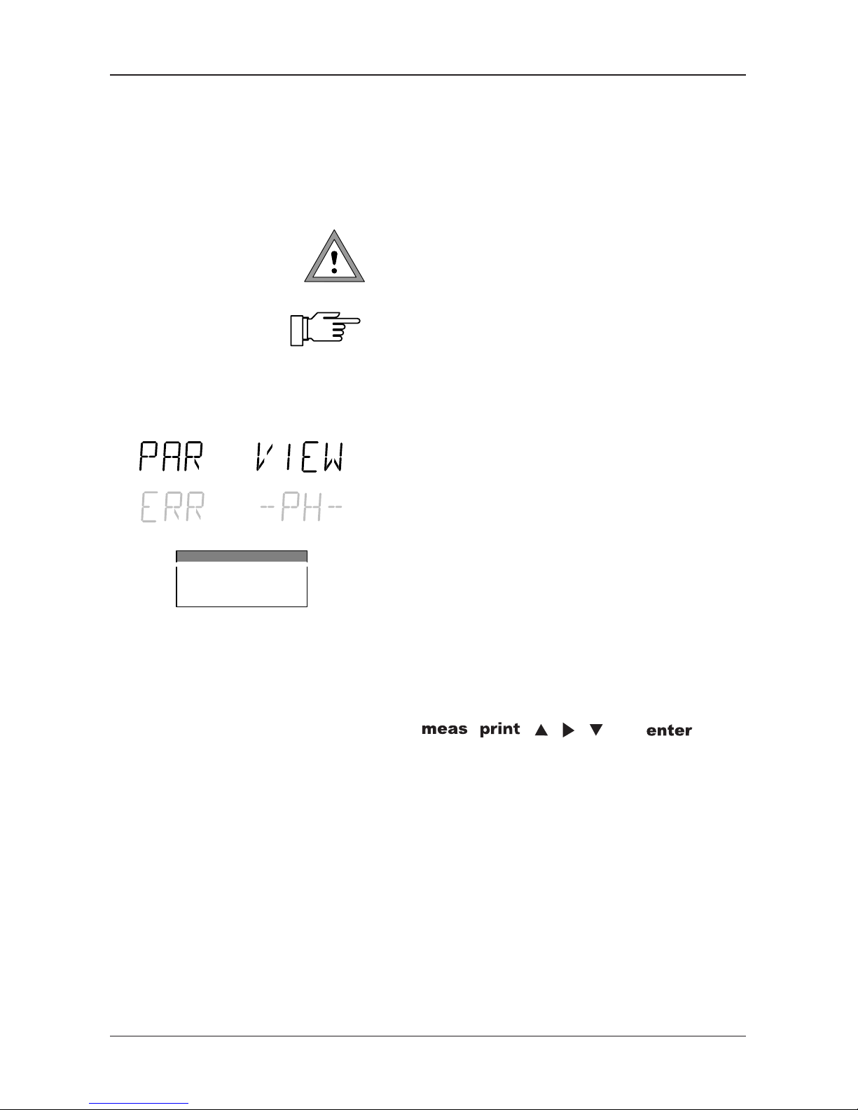
Warnings and notes
Instructions marked with this sign must be strictly
observed for reasons of your own safety! Failure to
follow these instructions may result in injuries.
Notes provide important information that should be
strictly followed when using the device.
Typical representations
Display example
A gray representation of the display text indicates a
flashing display.
Keys whose functions are described.
Markings in the text
Keys are represented by bold-faced text,
e.g. , , , , , , ... , .
on/standby
Page 5

Information III
Safety information
Be sure to read and observe the following instructions!
Before connecting the device to the power supply, make sure that the voltage corresponds with the rating given on the rating plate of the device.
Opening the device exposes live parts. Therefore, it shall not be opened. If a repair
should be required, return the de
vice to our factory.
If opening the device is inevitable, it shall first be disconnected from all voltage
sources.
Make sure that the mains supply has been disconnected.
Repair or adjustment of an opened device under voltage shall be carried out only by
a skilled person who is aw
are of the hazards involved.
Remember that the voltage across accessible parts of the open device may be dangerous to life.
Whenever it is likely that the protection has been impaired, the device shall be made
inoper
ativ
e and secured against unintended operation.
The protection is likely to be impaired if, for example:
• the device shows visible damage
• the device fails to perform the intended measurements
• after prolonged storage at temperatures above 70°C
• after severe transport stresses
Before recommissioning the device, a professional routine test in accordance with
EN 61010-1 m
ust be perf
ormed. This test should be carried out at our factory.
Page 6

]
Dokument-Nr. / Document
No. /
|
eCSOet
Zn
Aurbewahruns / Keepins / Garde en döpot
lNo.
document
I
Jürgen
cammin
(KB)
ililililil111ilililililililililil1il111il1ililililililililr1
I
wir, oie /
We, / Nous,
Niederspannungs-Richtlinie
/
Low-voltage directive
/
Directive basse
tension
Harmonisierte
Normen
/ Harmonised
Standards
/
Normes harmonisÖes
I
f ulv-Ricfrttinie
/
EMC directive
/
I
Directive CEM
I
Norm / Standard
/
Norme
I
Ausstellungsort,
-datum
/
Place and
date of
issue i
Lieu et
date d'Ömission
ililililllillililililililililililililililililililililililililililililililililllllllllllllllllllllllllll
E
G
-Konfo
rm itätserkl äru
n
g
EC Declaration of Gonformity
D6claration de Gonformit6 CE
Knick
)
Knick
Elektronische
Messgeräte
GmbH & Co.
KG
Beuckestr.
22
D-14163 Berlin
Jahr
der An0ringung der CE-Kennzerchnung
/
1 995
Year In whrch the CE
mark ng was affixed
/
L'annee
d'apposition du
marquage CE
Knick Elektronische
Messgeräte GmbH & Go.
KG
Beuckestr.
22, D-14163 Berlin
erklären
in alleiniger
Verantwortung, daß dieses
Produkt / diese Produkte,
declare under
our sole responsibility
that the
product
/
products,
d6clarons sous
notre seule
responsabilitÖ
que
le
produit
/ les
produits,
Labor-pH-Meter
765, Opt.
...
]
Produktbezeichnung
/
Product
identification /
Designation
du
produit
I
auf
welche(s) sich
diese Erklärung
bezieht,
mit allen
wesentlichen
Anforderungen der
folgenden
Richtlinien des
Rates übereinstimmen:
I
to
which this declaration
relates
is/are
in
conformity
with all essential
requirements
of the Council
Directives
relating
to:
J
auqueliauxquels
se röfere
cette döclaration
esVsont
conforme(s)
aux exigences
essentielles
de
la Directives du Conseil
relatives ä:
2006/95/EG
EN 61010-1:2001
20041'l08lEG
EN 61326-1:
2006
EN 61326-2-3:
2006
Berlin.
17.08.2009
Knick
Elektronische
Messgeräte
GmbH & Co.
KG
ppa.
Bernhard
Kusig
(Vice
President
Wolfgang
Page 7

Operation 1
The 765 Laboratory pH Meter
Package contents
After unpacking, please check the shipment for
completeness. The package should contain:
• 765 Laboratory pH Meter
• Power cord
• This instruction manual
Short device description
• The Model 765 is used for pH and ORP measurements in the laboratory.
• Temperature compensation is automatic using a
Pt 100 or Pt 1000 temperature probe or manual by
entering the temperature.
• Buffer solutions of eleven different, selectable
buffer sets are provided for calibration. Buffer recognition is automatic via Calimatic
®
.
• The calibration timer alerts you when the preset
interval between two calibrations has expired.
• Sensoface
®
electrode monitoring checks the connected electrode and provides information on the
electrode condition.
• Knick Fullcheck
®
device self-test checks the
device functions at the press of a key.
• Records of parameter setting, calibration and
diagnostics are particularly helpful for QM documentation to ISO 9000 and GLP. The records can
be directly output to a standard printer via the integrated serial interface.
Page 8
765 Laboratory pH Meter
2 Operation
2 Operation
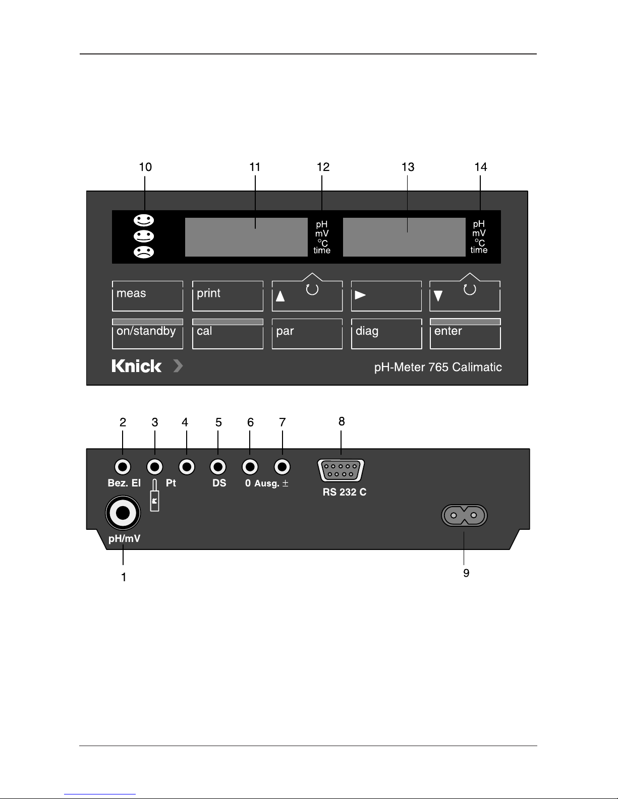
Meter design
1, 2 Electrode connection
3, 4 Temperature probe connection
5 DS connection
6, 7 Recorder output
8 Interface connection
9 Power input
10 Sensoface
®
display
11, 13 Displays
12, 14 Measurement symbols
Page 9
Operation 3
General information
Keypad
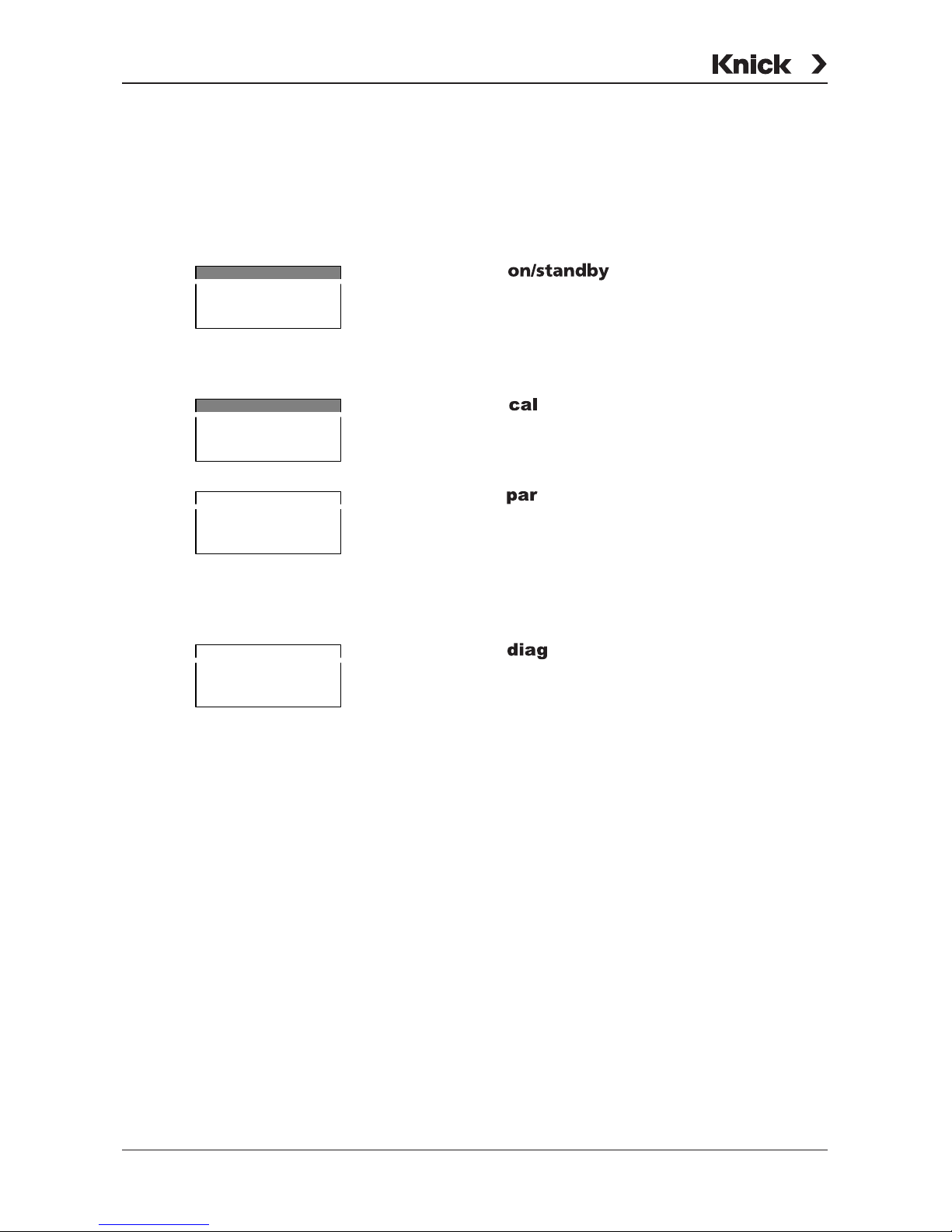
Pressing turns the pH meter on or
switches to standby mode. Standby mode is indicated by a lighted Sensoface
®
status display or two
measurement symbols. At power-on, the pH meter
automatically performs a short self test and then
goes to measuring mode.
Pressing opens the Calibration level. On the
Calibration level the pH meter is adapted to the
electrode. You can conduct either a one or a twopoint calibration.
Pressing opens the Parameter level. On the
Parameter level all variable device parameters are
set.
• In the VIEW menu you can view all parameters.
• In the EDIT menu you can also edit the parame-
ters.
Pressing opens the Diagnostics level. On the
Diagnostics level you can get information on the
electrode condition, view the current electrode
data, and perform a complete device self test.
• The Sensoface
®
menu lists the individual param-
eters of Sensoface
®
automatic electrode monitor-
ing with the corresponding evaluations.
• The Electrode Data menu shows the values for
zero and slope of the electrode determined during
last calibration, the remaining time until the next
due calibration determined by the calibration timer
and the data of the electrode statistics.
• With the Knick Fullcheck
®
menu, a complete
device self-test is performed.
on/standby
cal
par
diag
Page 10
765 Laboratory pH Meter
4 Operation
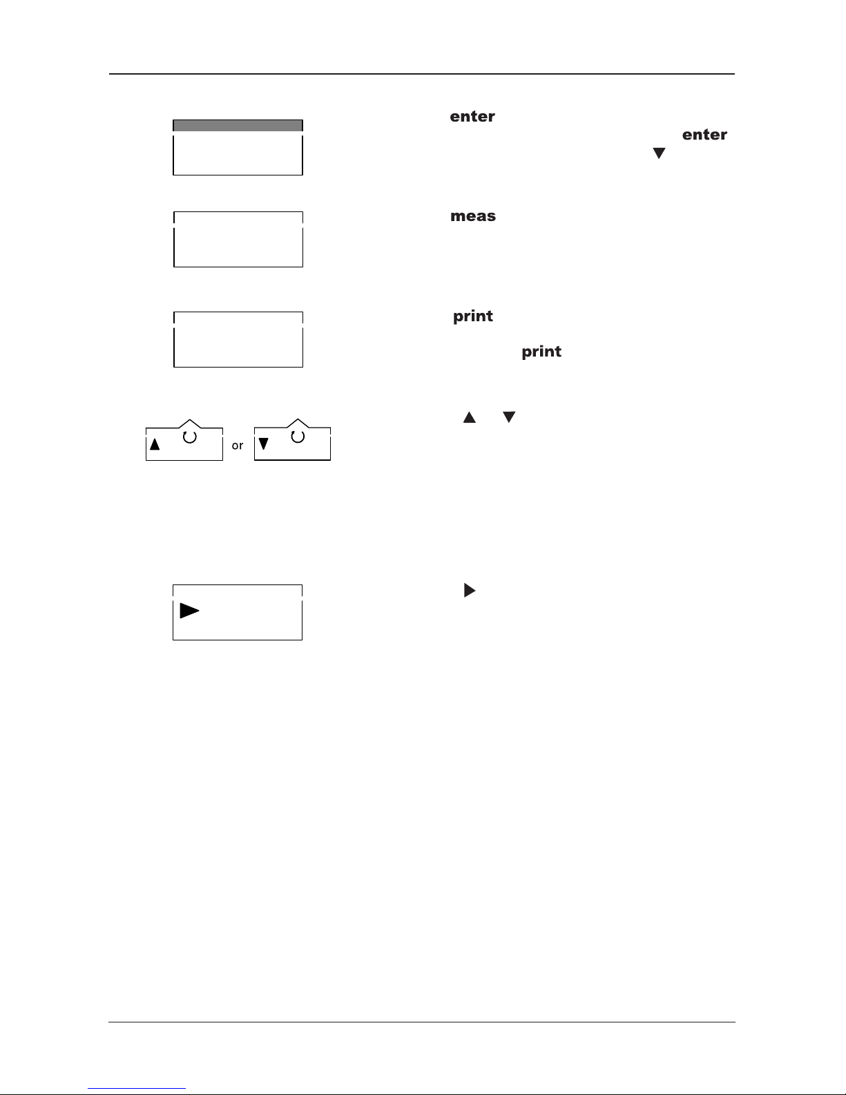
Pressing stores an entered parameter. If
you have not made any changes, pressing
selects the next parameter (instead of ).
Pressing exits a function level and returns
you to measuring mode.
Pressing in measuring mode prints out the
current pH, mV and temperature values with date
and time. Pressing on one of the function
levels prints out a complete record of the data
stored.
• Pressing or in measuring mode selects the
measured variable for the left or right display,
respectively. The corresponding measurement
symbol appears on the right side of the display.
• On the function levels these keys are used to
select parameters.
• When entering numerical parameters, they are
used to increment or decrement a numeral.
• Pressing in the EDIT menu of the Parameter
level selects the parameter you want to edit.
• Pressing this key in the VIEW menu or on the
Diagnostics level stops automatic line scrolling.
enter
meas
print
Page 11
Operation 5
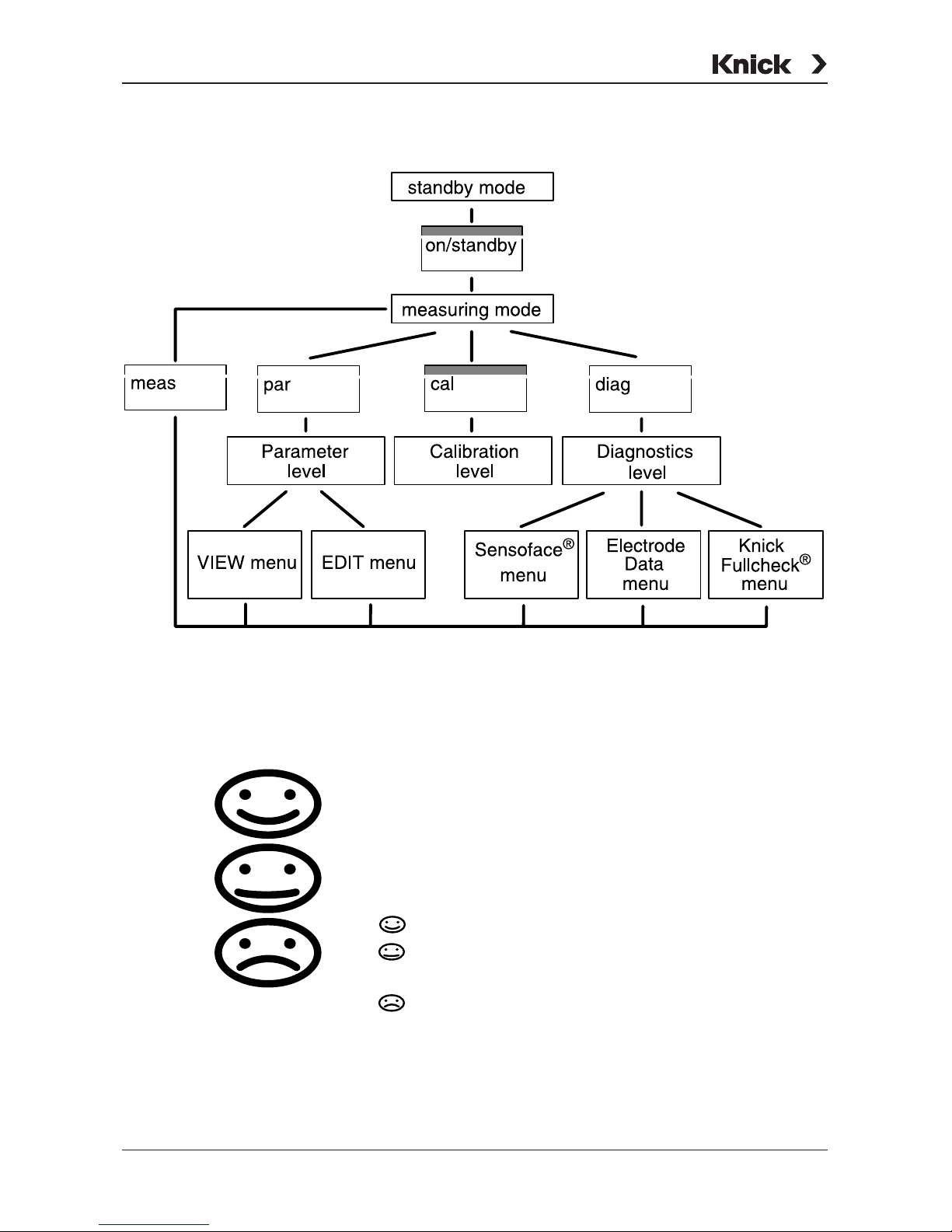
Menu structure
Sensoface® automatic
electrode monitoring
Sensoface® automatic electrode monitoring provides information on the electrode condition. Zero
point, slope and response time are evaluated during calibration.
Impedance, dry-out and the calibration timer are
evaluated during measurement and in standby
mode.
A summary of the individual results is expressed by
three face symbols.
The electrode is in good condition.
The electrode is still usable, but should be calibrated.
The electrode urgently requires calibration. If the
display does not change after calibration, replace
the electrode.
Page 12

765 Laboratory pH Meter
6 Operation
More detailed information on the indicated electrode condition and the individual parameter evaluations is given in chapter ”Diagnostics level” (see
Pg. 21).
Sensoface
®
was specially designed for monitoring
pH electrodes. Since ORP electrodes have completely different characteristics, they provoke
invalid Sensoface
®
displays. Therefore, you should
disable Sensoface® for ORP measurements.
Sensoface® display can also be degraded when
you use a pH simulator.
Power-on and start-up
Mains supply The pH meter is designed for 230 VAC supply
(Option 363: 115 V AC). Connect the power input of
the pH meter to a mains outlet using the included
power cord.
If the pH meter is disconnected from mains, clock
and calibration timer are not affected (reserve
power approx. 1 year). Settings, calibration and
diagnostics data remain permanently stored.
Electrode connection The pH meter can be combined with commercial
electrodes: with nominal zero at pH 7 and with
• standard coaxial plug to DIN 19 262 and/or
•4 mm banana plug.
For special electrodes with differing specifications,
we offer Option 346 (nominal zero and slope of
electrode user defined).
Page 13
Operation 7
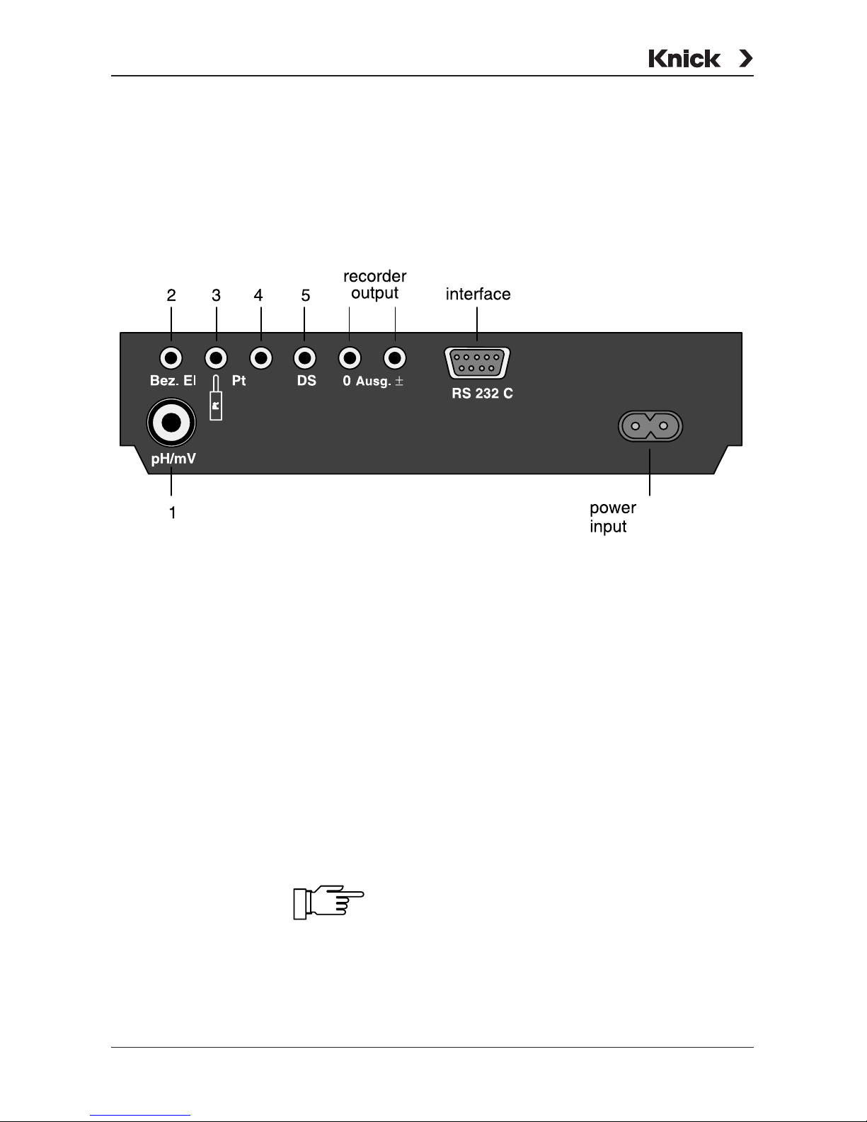
Connection Socket
Combination electrode 1
Single sensing electrode 1
Single reference electrode 2
Temp probe of combination electrodes 3
(Electrodes with integrated temp probe)
Separate temperature probe 3, 4
If no temperature probe is connected, the meter
uses the manually selected temperature. The decimal point of the temperature display flashes.
If you use double platinum electrodes for voltametrical indication of titrations:
• Connect the banana plugs of the double platinum
electrode to sockets 1 and 2.
• To connect the 10 µA polarization current to the
double platinum electrode, connect socket 5 with
the inner pole of socket 1 (e.g. using a banana
plug with cross hole).
For the RS 232 interface, a shielded cable must be
used (e.g. ZU 0152, ZU 0153).
Page 14
765 Laboratory pH Meter
8 Operation
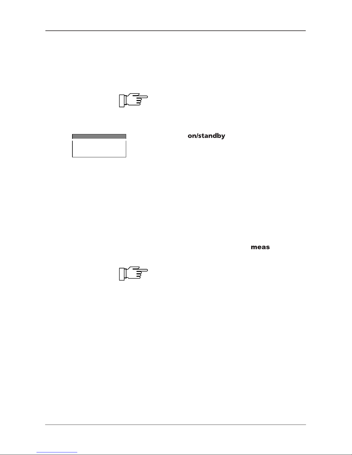
Standby mode If the meter is connected to a mains outlet but not
switched on, it is in standby mode. This indicated by
a lighted Sensoface
®
display.
If Sensoface® display is turned off, two measurement symbols are lighting.
Clock and calibration timer are running in standby
mode. Knick Drycheck
®
and impedance monitoring
are active. Settings, calibration and diagnostics
data remain permanently stored. The interface is
deactivated.
Pressing switches the meter to measuring mode.
At power-on, the meter performs a short check:
• Simultaneous lighting-up of all display segments,
measurement symbols and Sensoface
®
displays
• Display of model name PH 765
• Display of software version
• Display of nominal buffer values of selected buffer
set
• Memory test
To stop the short check, press .
Do not disconnect the meter from mains if you do
not use it. Only when the meter remains in standby
mode can the electrode be monitored and the battery for the clock be charged.
on/standby
Page 15
Operation 9
Measuring mode In measuring mode both displays indicate the
respectively selected measured variable. The variable for the left display is selected using , for the
right display using . The corresponding measurement symbol is shown on the right side of the
display. You can choose any of the following variables:
• pH value
• Electrode potential [mV]
• Temperature [°C]
• Time
A flashing point on the temperature display indicates that no temperature probe is connected. The
meter now uses the manually selected temperature.
If you have connected a printer, pressing in
the measuring mode gives you a printout of the currently measured values with date and time.
print
Page 16
765 Laboratory pH Meter
10 Operation
Parameter level
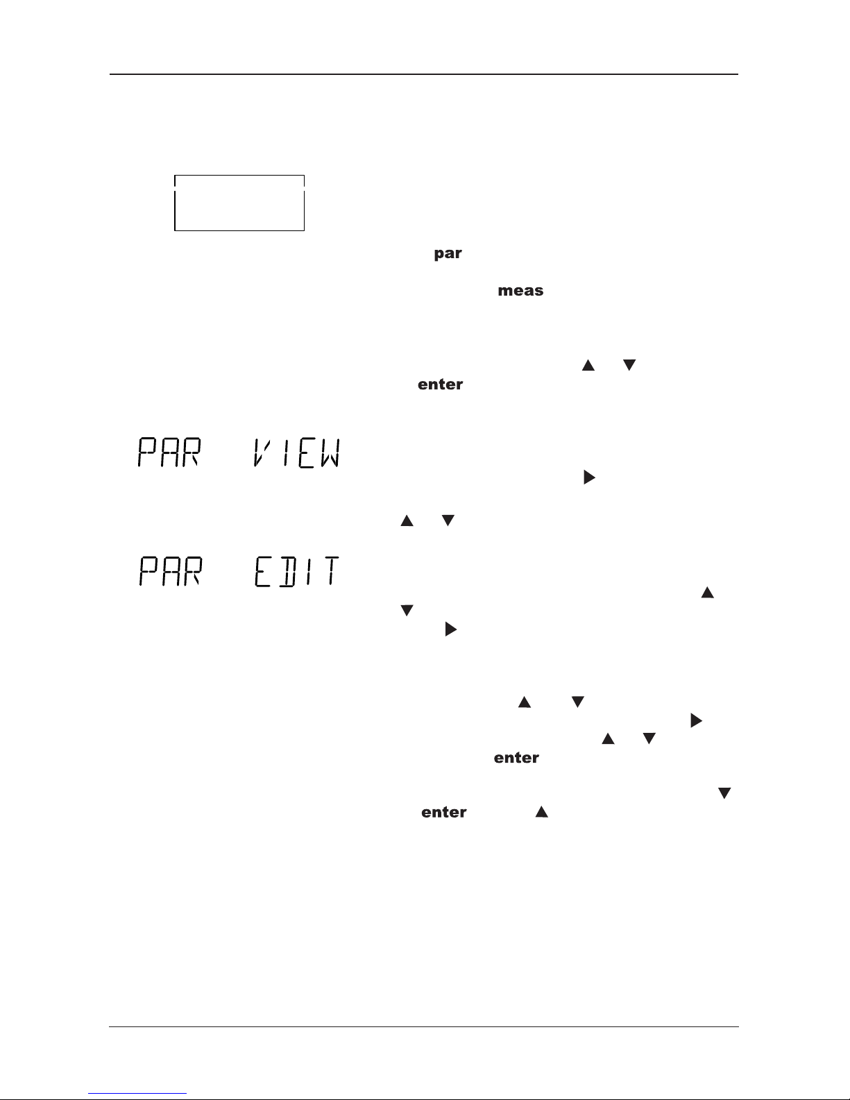
On the Parameter level all variable device parameters are set. Parameters are set in dialog mode
using different menus.
Activating parameter setting Press to exit measuring mode and access the
main menu of the Parameter level. To exit Parameter level, press . It is exited automatically
when all parameter setting steps have run through.
Main menu In the main menu of the Parameter level you select
the desired submenu using or . Pressing confirms your choice and gives access
to the corresponding submenu.
The VIEW menu automatically displays all parameters . Settings cannot be changed, however.
• To hold the display, press .
• To scroll one line forwards or backwards, press
or , respectively.
In the EDIT menu you can view and edit all parameters.
• Select the parameter you want to edit using or
.
• Press to start parameter editing. To indicate
that the parameter can now be edited, the right
display flashes.
• While the right display is flashing, you can edit the
parameter using and . When entering
numerical values, select the position using and
then count up or down using or .
• Confirm with . The selected value will be
stored and the next parameter displayed.
• You can now select the next parameter using
or or press to exit the Parameter level.
par
Page 17
Operation 11
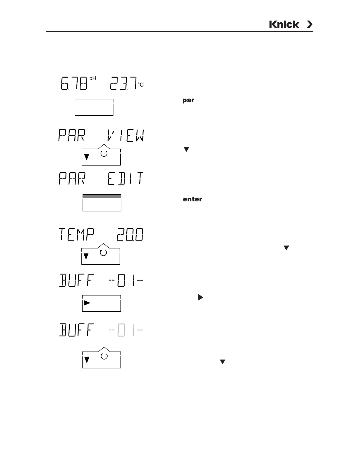
Typical setting procedure The meter is factory set to calibration buffer set 01
(Mettler Toledo technical trade buffers). However,
you want to calibrate using the technical buffer
solutions to DIN 19 267, calibration buffer set 03.
Therefore, you must select buffer set 03 on the
Parameter level.
Press to access the Parameter level.
Press to select the EDIT menu.
Press to open the EDIT menu.
Select buffer set parameter BUFF using .
Now press to change the buffer set. The right
display will flash.
Select buffer set 03, technical buffers to
DIN 19 267, using .
par
enter
Page 18
765 Laboratory pH Meter
12 Operation
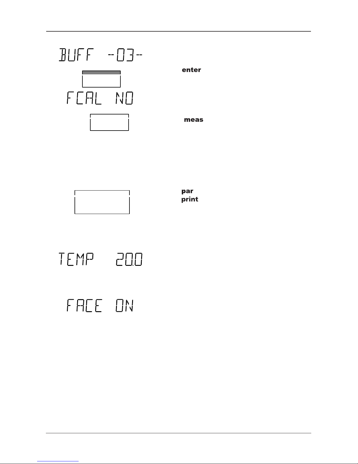
Press to confirm your choice. Buffer set 03
will be stored and the next parameter displayed.
Press to exit Parameter level.
Printout of parameter record If you have connected the pH meter to a printer, you
can print out all stored parameter settings.
Press to open the Parameter level.
Press to print out all settings. The meter will
automatically return to measuring mode.
Parameters In the following, the individual parameters and their
possible settings will be explained.
Manual temperature (–50 to +150 °C)
If no temperature probe is connected, the meter
uses the manually selected temperature. In this
case, the decimal point of the temperature display
will flash in measuring mode.
Sensoface
®
(off / on)
Display of Sensoface® electrode monitoring can be
turned on or off. If Sensoface® display is turned off,
standby mode is indicated by two lighted measurement symbols. Display of Sensoface
®
parameters
on the Diagnostics level is not affected.
For information on Sensoface®, refer to chapter
”Sensoface® menu” (Pg. 22).
enter
meas
print
Page 19
Operation 13
Sensoface® was specially designed for monitoring
pH electrodes. Since ORP electrodes have completely different characteristics, they provoke
invalid Sensoface
®
displays. Therefore, you should
disable Sensoface® for ORP measurements. Sensoface
®
display can also be degraded when you
use a pH simulator.
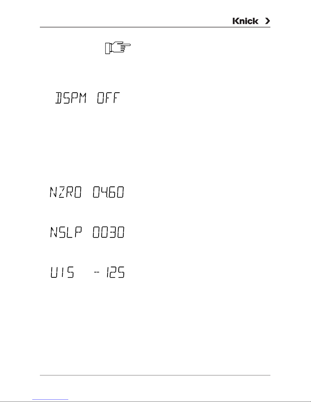
Displaymatic® (off / on)
Displaymatic® can be turned on or off. Displaymatic
®
ensures a stable measured value display in
case of rapid changes of the pH value. This allows
for easy reading of the value. It is achieved by suppressing the two running digits behind the decimal
point. When the value changes slowly, only the last
digit will be suppressed. When the value has stabilized, all digits will be displayed.
Only for meters
with Option 346:
Setting the nominal electrode zero point and slope:
Nominal zero (pH 0.00 to 14.00)
For special electrodes with differing nominal zero.
The entered zero point is taken as reference for
Calimatic
®
. The exact zero point will be determined
during calibration.
Nominal slope (25.0 to 61.0 mV/pH)
For special electrodes with differing nominal slope.
The entered slope is taken as reference for Calimatic
®
. The exact slope will be determined during
calibration.
Isothermal potential (–500 to +500 mV)
The isothermal potential entered here is automatically taken into account for calibration and pH
determination.
Page 20
765 Laboratory pH Meter
14 Operation
Calibration buffer set (00 to 10)
Select the buffer set with the buffer solutions you
are using. The meter has stored eleven different
calibration buffer sets.
(see Buffer sets Pg. 49).
The meter can only operate properly when the
buffer solutions used correspond to the selected,
activated buffer set.
Other buffer solutions, even those with the same
nominal values, may demonstrate a different temperature behavior.
This leads to measurement errors.
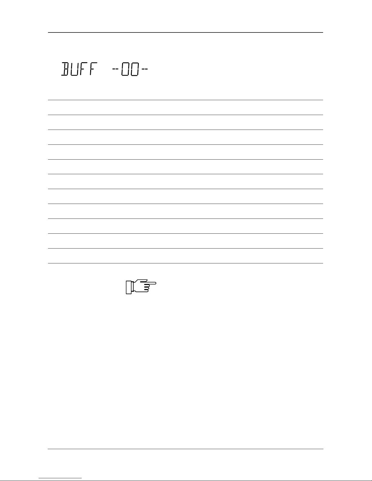
BUFF –00– Knick technical buffers
pH 2.00 4.01 7.00 9.21 (25°C
BUFF –01– Mettler-Toledo technical buffers (correspond to Ingold technical buffers)
pH 2.00 4.01 7.00 9.21 (25°C)
BUFF –02– Merck/Riedel
pH 2.00 4.00 7.00 9.00 12.00 (20 °C)
BUFF –03– DIN19267
pH 1.09 3.06 4.65 6.79 9.23 12.75 (25°C)
BUFF –04– DIN19266 and NIST (NBS)
pH 1.679 4.006 6.865 9.180 12.454 (25°C)
BUFF –05– Merck/Riedel
pH 1.00 3.00 6.00 8.00 10.00 13.00 (20°C)
BUFF –06– Merck
pH 4.66 6.88 9.22 (20°C)
BUFF –07– Ciba(94)
pH 2.06 4.00 7.00 10.00
BUFF –08– customer specific
pH 2.00 4.62 7.00 8.20 10.00 12.00 (20°C)
BUFF –09– customer specific
pH 2.00 4.01 7.00 9.21 12.00 (25 °C/20 °C)
BUFF -10– Mettler Toledo (USA)
pH 4.00 7.00 10.01 (25 °C)
Page 21
Operation 15
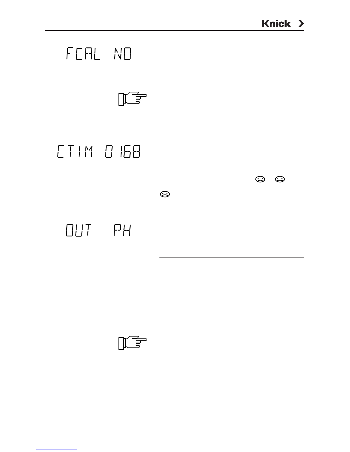
First calibration (no / yes)
With YES, all statistics data will be erased with the
next calibration, and the new electrode data will be
stored as First Calibration data. After calibration,
this parameter will automatically reset to NO.
You should always perform this step when replacing the electrode so that a new statistic is started for
the new electrode. For further information on electrode statistics, refer to chapter ”Diagnostics level”
(Pg. 25).
Calibration timer (0 to 2000 h)
With the calibration timer, you can preset a time
interval for the next due calibration. After approx.
80 % of the preset interval have expired, the timer
sets the Sensoface
®
display from to . After
the total interval has expired, the display is set to
. The timer is reset by calibration. To turn off the
timer, enter 0 as interval time.
Recorder output (pH / mV / °C / PRNT)
The recorder output can output pH value, measured voltage or temperature.
With PRNT selected, the recorder output serves as
input for activating a print command. With a simple
contact, such as a foot switch, the currently measured values can be printed. For further information, refer to chapter ”Trueline
®
recorder output”
(Pg. 30).
Do not apply an external voltage to the recorder
output. The meter might be damaged.
Output voltage:
OUT PH 100 mV/pH
OUT mV 1 mV/mV
OUT ° C 10 mV/°C
Page 22
765 Laboratory pH Meter
16 Operation
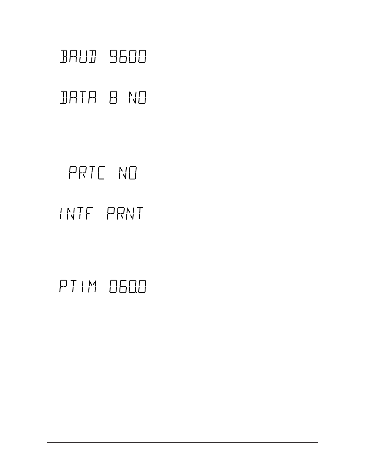
Baud rate (600 / 1200 / 2400 / 4800 / 9600)
Here, you can select the interface transmission
rate.
Data format (8 NO / 7 EV / 7 OD)
You can choose between:
Transmission protocol (NO / XON)
The interface can operate either without transmission protocol or with XON/XOFF protocol.
Interface (PRNT / PC)
For direct printer control, select PRNT. You can
directly print out measured values and records. To
connect the meter to a computer (PC), select PC.
The pH meter will be completely computer controllable. All measured values and parameters will be
retrievable via computer.
Print interval timer (0.1 to 999.9 min)
This step only appears if you have set the interface
for printer control. The print interval timer presets
an interval for printout of currently measured values
with time and date. To turn off the timer, enter 0 as
interval time.
Data word length Parity
8 bits none
7 bits even
7 bits odd
Page 23
Operation 17
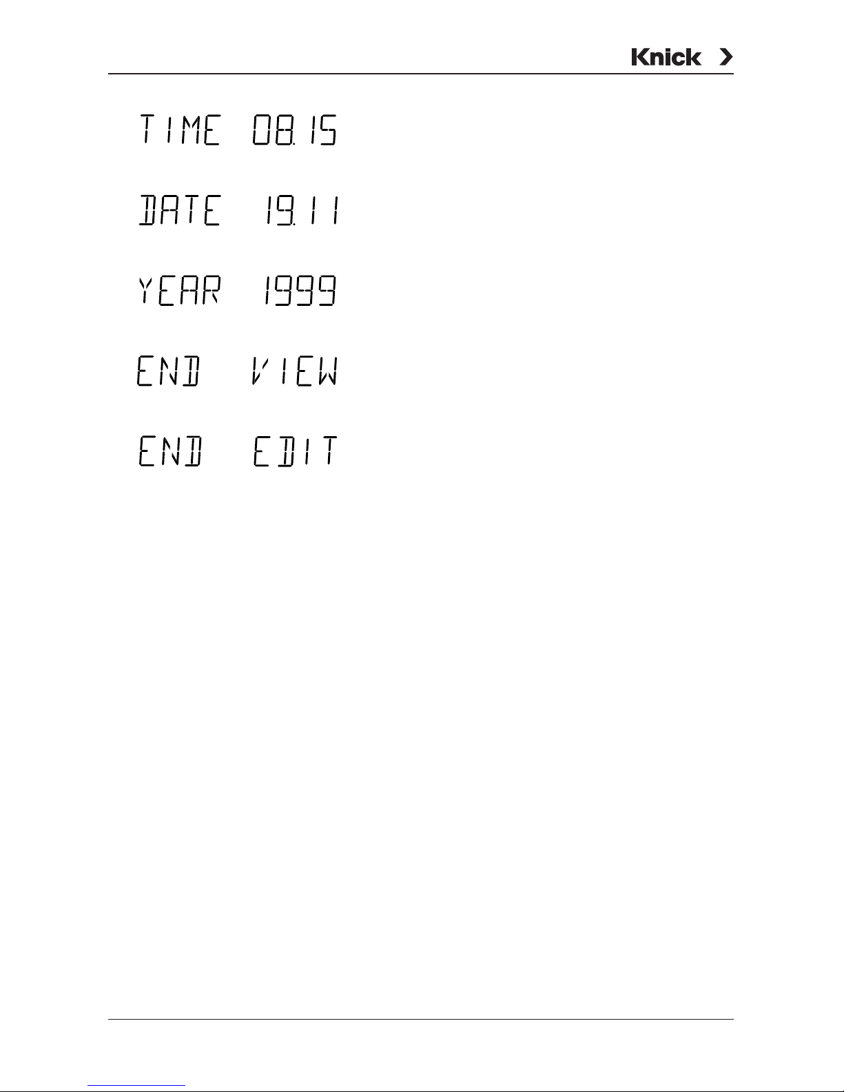
Time
Date
Year
End of VIEW menu.
End of EDIT menu.
Page 24
765 Laboratory pH Meter
18 Operation
Calibration level
Calibration adjusts the pH meter to the electrode in
use. It is adjusted for zero and slope of the electrode.
You only have to select the used buffer set once on
the Parameter level. The patented Calimatic
®
then
automatically recognizes the buffer solution in use,
calculates zero point and slope of the electrode and
adjusts correspondingly. In addition, the Model 765
measures the electrode response time during calibration.
Activating calibration Press to exit measuring mode and access the
Calibration level. You can stop calibration at any
time by pressing .
The meter can only operate properly when the
buffer solutions used correspond to the buffer set
selected on the Parameter level. Other buffer solutions, even those with the same nominal values,
may demonstrate a different temperature behavior.
This leads to measurement errors.
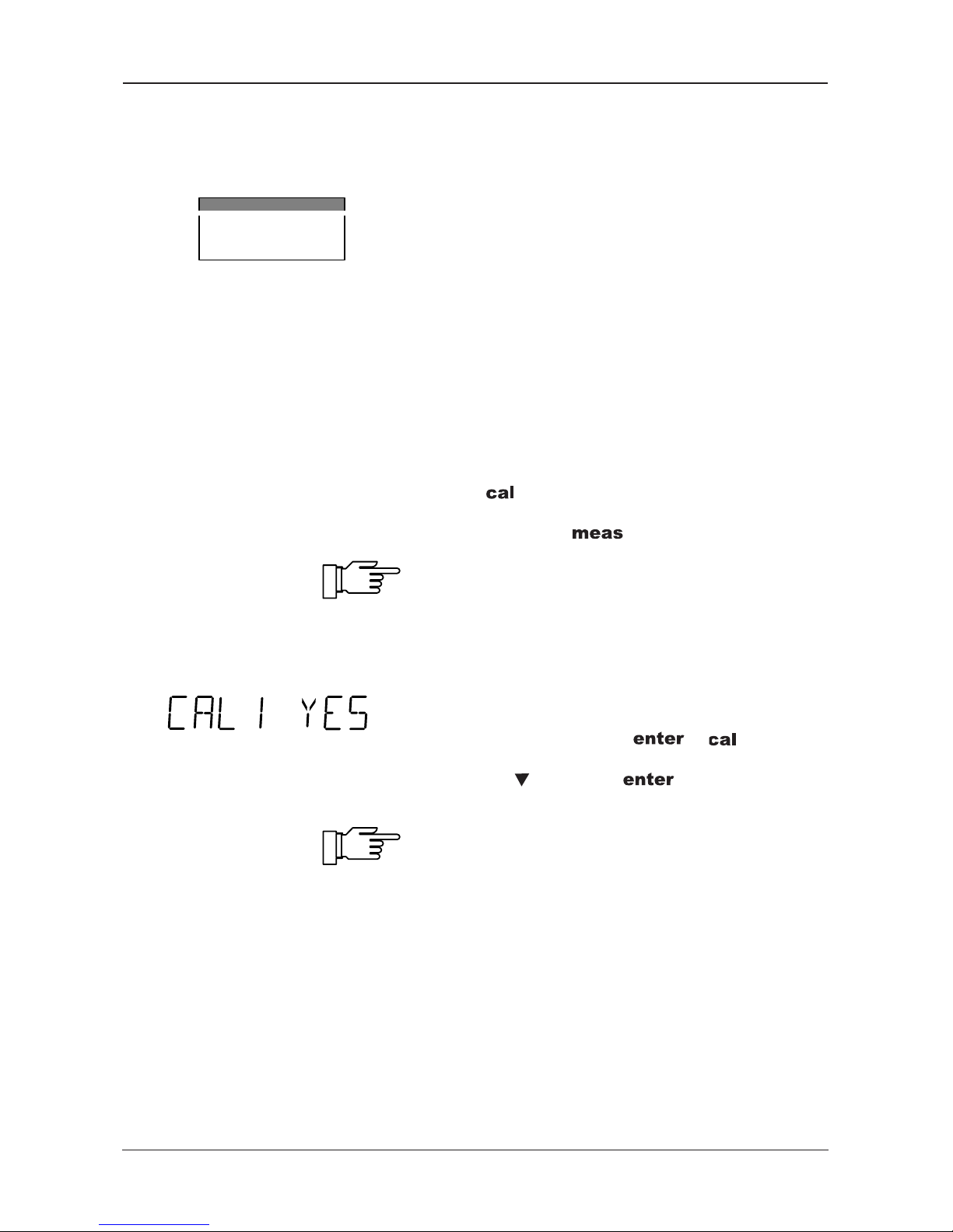
Immerse the electrode and temperature probe in
the first buffer solution. This can be any of the
selected solutions. Press or to start calibration. If you do not want to calibrate, select CAL1
NO using and press to exit Calibration
level.
The response time of the electrode and temperature probe is considerably reduced if the electrode
is first moved about in the buffer solution and then
held still. The values will stabilize more quickly.
cal
Page 25
Operation 19
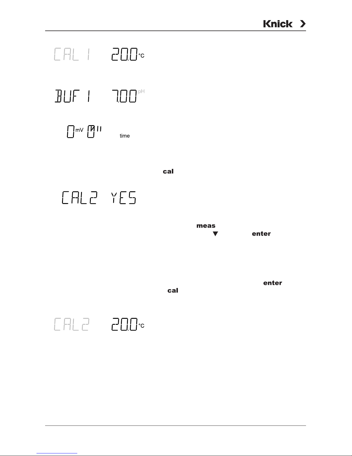
During buffer recognition CAL 1 is flashing. The
right display reads the measured temperature.
When you use manual temperature compensation,
the entered temperature is displayed. This is indicated by a flashing decimal point.
The nominal value of the identified buffer solution is
displayed for approx. 5 sec. Electrode and temperature probe still remain in the first buffer solution.
Stability of the electrode is checked. The left-hand
display reads the measured mV value. The righthand display shows a running clock measuring the
electrode response time. For each revolution
(4 sec), a mark is added to the tally beside the
clock. Stability check can be stopped by pressing
. However, this reduces calibration accuracy.
Calibration with the first buffer is terminated. Take
the electrode and temperature probe out of the
solution and rinse them thoroughly.
• If you only want to perform a one-point calibra-
tion, press to stop calibration, or select
CAL2 NO using and press to exit the
Calibration level. The meter will display the new,
calculated zero point and the old slope and return
to measuring mode.
• If you want to perform a two-point calibration,
immerse the electrode and temperature probe in
the second buffer solution. Press or
to restart calibration. The calibration process
runs again as for the first buffer.
Buffer recognition, CAL 2 flashing, display of temperature
Page 26
765 Laboratory pH Meter
20 Operation
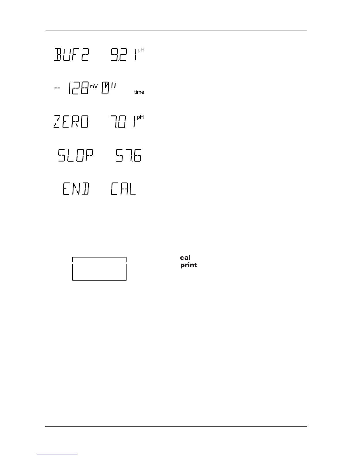
Display of nominal buffer value for approx. 5 sec
Check of electrode stability and response time
Display of zero point determined for the electrode
Display of slope determined for the electrode
End of calibration
Printing calibration record If you have connected the meter to a printer, you
can print out a record of the last calibration.
Press to open the Calibration level.
Press to print out the complete record of the
last calibration. The meter will automatically return
to measuring mode.
print
Page 27
Operation 21
Diagnostics level
On the Diagnostics level the complete pH measurement equipment is checked. This also serves for
quality management to ISO 9000.
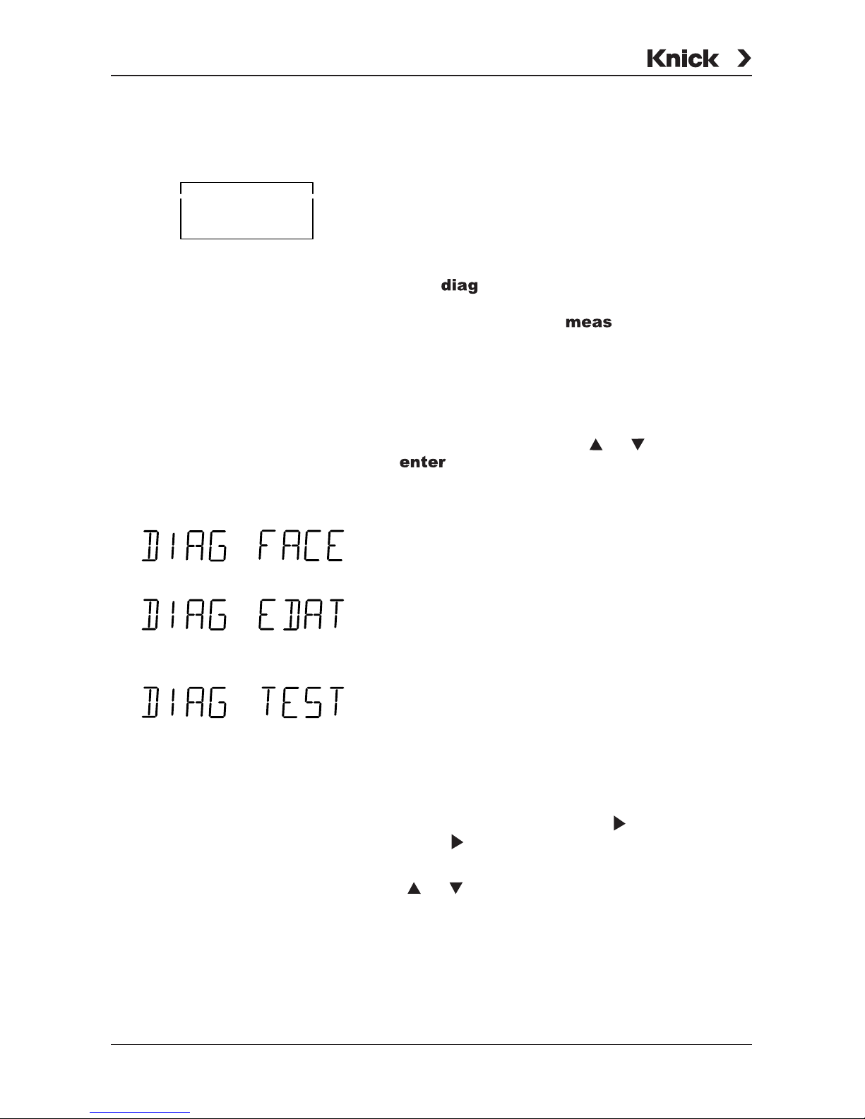
Activating diagnostics Press to exit measuring mode and access
the main menu of the Diagnostics level. To exit
Diagnostics level, press . It is exited automatically when all diagnostics functions have been
performed.
Main menu In the main menu you select the desired function of
the Diagnostics level using or . Pressing
gives access to the corresponding sub-
menu.
The Sensoface
®
menu shows the states of the cri-
teria that control Sensoface
®
display.
The Electrode Data menu shows the electrode data
calculated during last calibration, the calibration
timer count and the electrode statistics.
The Knick Fullcheck
®
menu provides a complete
device self test to check the operability of the individual device components.
All submenus are run automatically but can be influenced via keypad.
• To stop the sequence, press . To restart it,
press once more.
• To scroll one step forwards or backwards, press
or , respectively.
diag
Page 28
765 Laboratory pH Meter
22 Operation
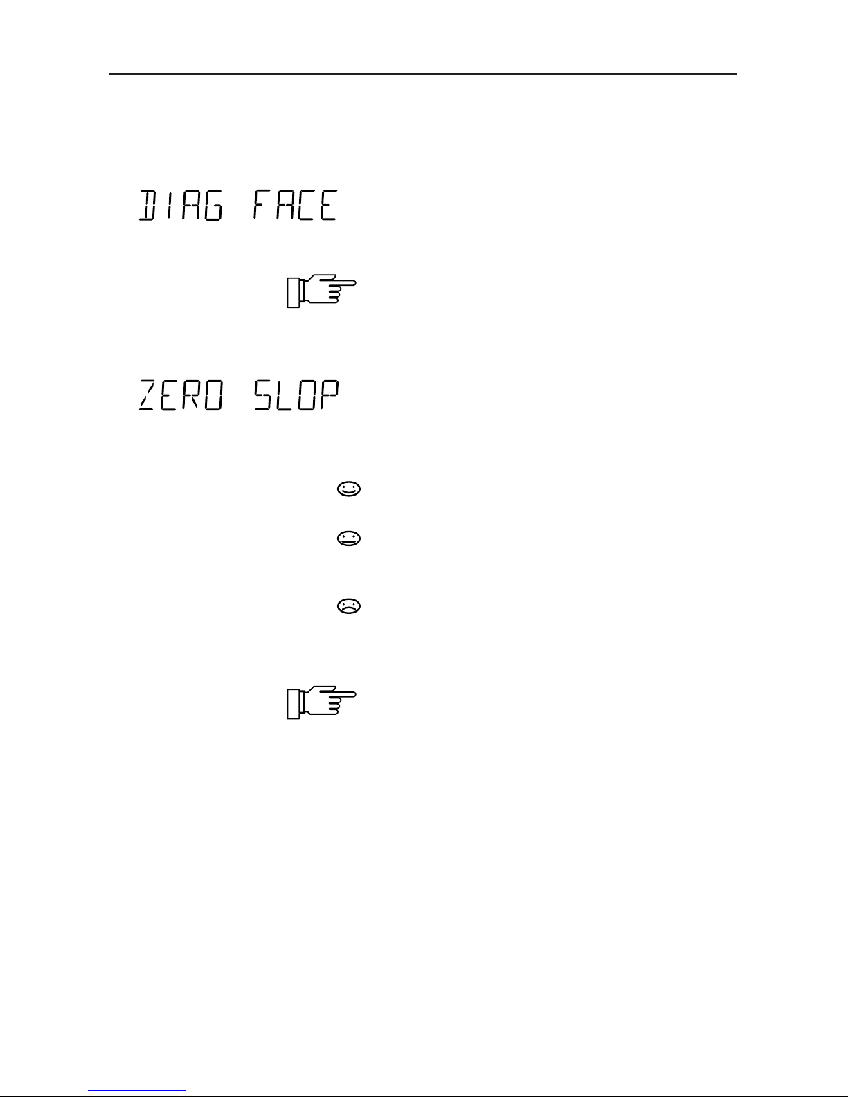
Sensoface® menu In the Sensoface
®
menu you see the criteria that
control Sensoface® display. Each criterion is displayed separately with the corresponding evaluation. This gives you important information on the
condition of you electrode. Sensoface
®
alerts you
in time for possible errors or aging of your electrode.
The worsening of a Sensoface
®
criterion leads to
the devaluation of the Sensoface® display. This
devaluation is permanent. An improvement can
only take place after a calibration.
Here, the Sensoface
®
display provides information
on zero and slope of the electrode. For the exact
zero and slope values, refer to the Electrode Data
menu.
Zero and slope of the electrode are okay.
Zero and slope of the electrode are still okay. However, the electrode should be replaced soon.
Zero and/or slope of the electrode have reached
values which no longer ensure proper calibration. It
is advisable to replace the electrode.
The values for zero and slope are determined during calibration only. Therefore, correct information
depends on a proper calibration. Make sure that
you always use correct and pure buffer solutions.
Page 29

Operation 23
The Sensoface® display provides information on
the electrode’s response time. This is the time the
electrode requires for delivering a stable measured
value. The value determined during calibration.
Wear and aging, but also wrong treatment (such as
dry storage) can reduce the gel layer of the glass
membrane. This results in a longer response time.
The electrode gets sluggish.
The electrode promptly adjusts to the measured
value.
The electrode adjusts slowly. You should consider
replacing it. It may be possible to achieve an
improvement by cleaning, or in the case of an electrode stored dry, by ”watering”.
The electrode adjusts very slowly to the measured
value. Correct measurement is no longer ensured.
The electrode should be replaced.
Page 30
765 Laboratory pH Meter
24 Operation
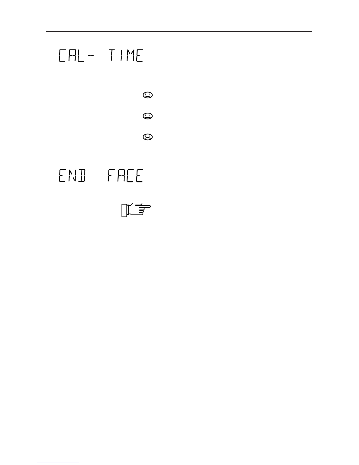
On the Parameter level, the calibration timer allows
to preset a time interval for the next due calibration.
The calibration timer keeps running in standby
mode and with mains supply disconnected.
The calibration interval is still running.
Over 80 % of the calibration interval have run out.
The calibration interval has been exceeded.
End of Sensoface
®
menu.
Sensoface® was specially designed for monitoring
pH electrodes. Since ORP electrodes have completely different characteristics, they provoke invalid Sensoface
®
displays. Therefore, you should
disable Sensoface® for ORP measurements.
Sensoface
®
display can also be degraded when
you use a pH simulator.
Page 31
Operation 25
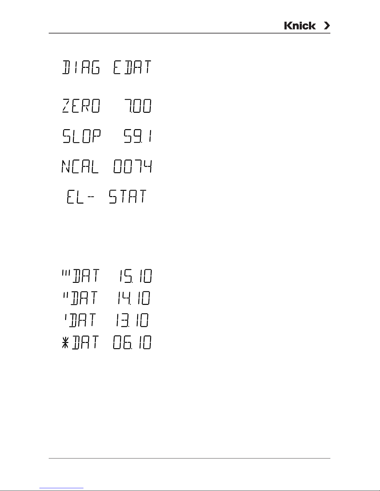
Electrode Data menu The Electrode Data menu shows the values for
zero and slope of the electrode calculated during
the last calibration, the cal timer count, and the
electrode statistics.
Display of electrode zero determined during last
calibration.
Display of electrode slope determined during last
calibration.
Display of time in hours until the next calibration is
requested by the timer.
The electrode statistics include the electrode zero,
slope and response time of the last three calibrations with corresponding date and time. In addition,
the data of the first calibration (see Pg. 15) performed on this electrode are provided. This allows
you to evaluate electrode behavior over its whole
life span. Since the data are very comprehensive,
they should be printed out or read out via computer.
Date of last calibration
Date of second last calibration
Date of third last calibration
Date of first calibration
Page 32
765 Laboratory pH Meter
26 Operation
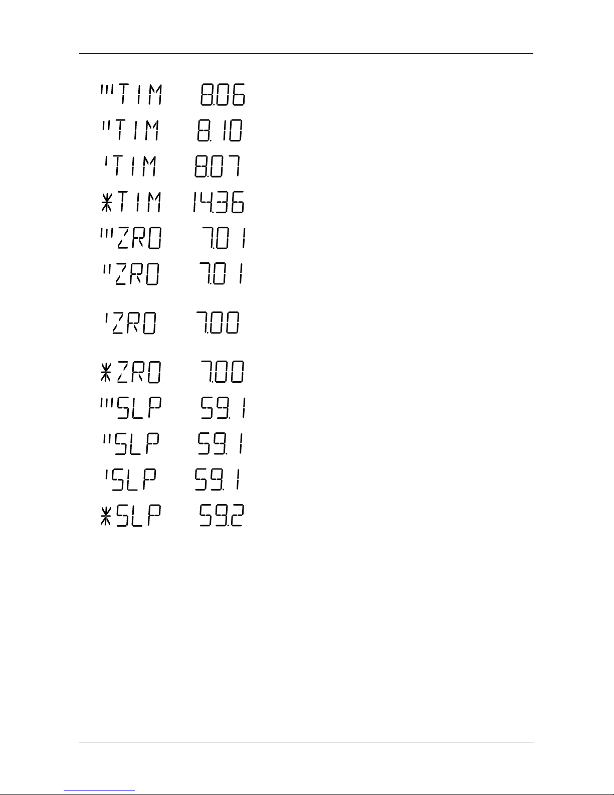
Time of last calibration
Time of second last calibration
Time of third last calibration
Time of first calibration
Electrode zero determined during last calibration
Electrode zero determined during second last calibration
Electrode zero determined during third last calibration
Electrode zero determined during first calibration
Slope determined during last calibration
Slope determined during second last calibration
Slope determined during third last calibration
Slope determined during first calibration
Page 33
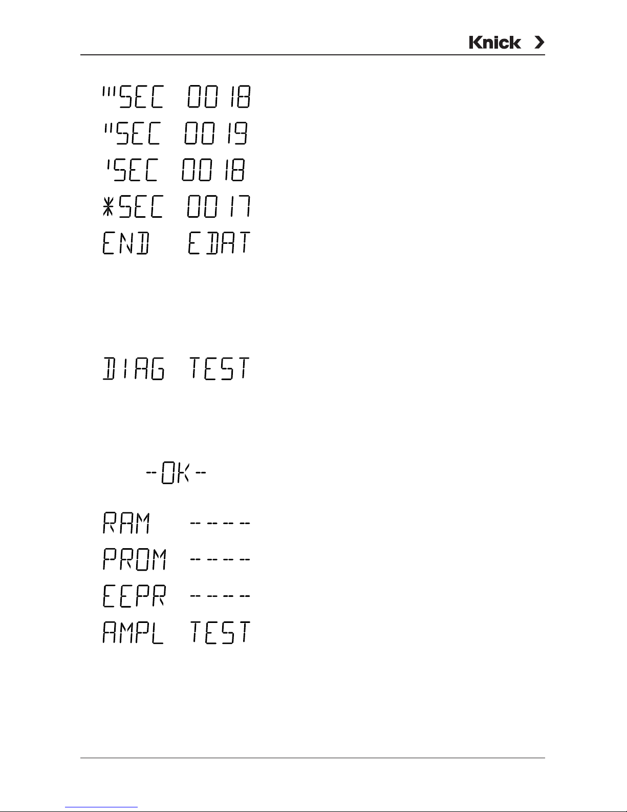
Operation 27
Electrode response time of last calibration
Electrode response time of second last calibration
Electrode response time of third last calibration
Electrode response time of first calibration
End of Electrode Data menu.
Knick Fullcheck® menu With the Knick Fullcheck
®
menu, a complete device
self-test is performed. The complete measuring circuitry, measured value processing, memories, display and keypad are checked and each result is
displayed. The tests run automatically. Only during
keypad testing you have to press the requested
keys. Longer testing periods are indicated by a little
running clock on the right display.
Successful testing is confirmed by OK on the right
display.
RAM test
EPROM test
EEPROM test
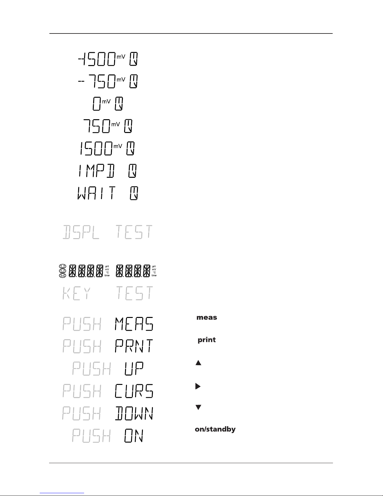
Amplifier linearity test: Using an integrated, highprecision reference, the complete measuring circuitry from input amplifier to recorder output is
checked. The displayed mV values lie across the
recorder output. The electrode is internally disconnected from the amplifier.
Page 34
765 Laboratory pH Meter
28 Operation
Linearity test at -1500 mV
Linearity test at -750 mV
Linearity test at 0 mV
Linearity test at +750 mV
Linearity test at +1500 mV
Test of impedance measuring circuit
Amplifier linearity test is terminated. The device
takes a few seconds to bumplessly reconnect the
electrode to the amplifier.
Display test: All Sensoface
®
indicators, all segments of the two LED displays and all measurement symbols light up.
Check whether really everything is lighting.
During keypad testing, you are prompted to press
the corresponding key.
Press .
Press .
Press .
Press .
Press .
Press .
Page 35
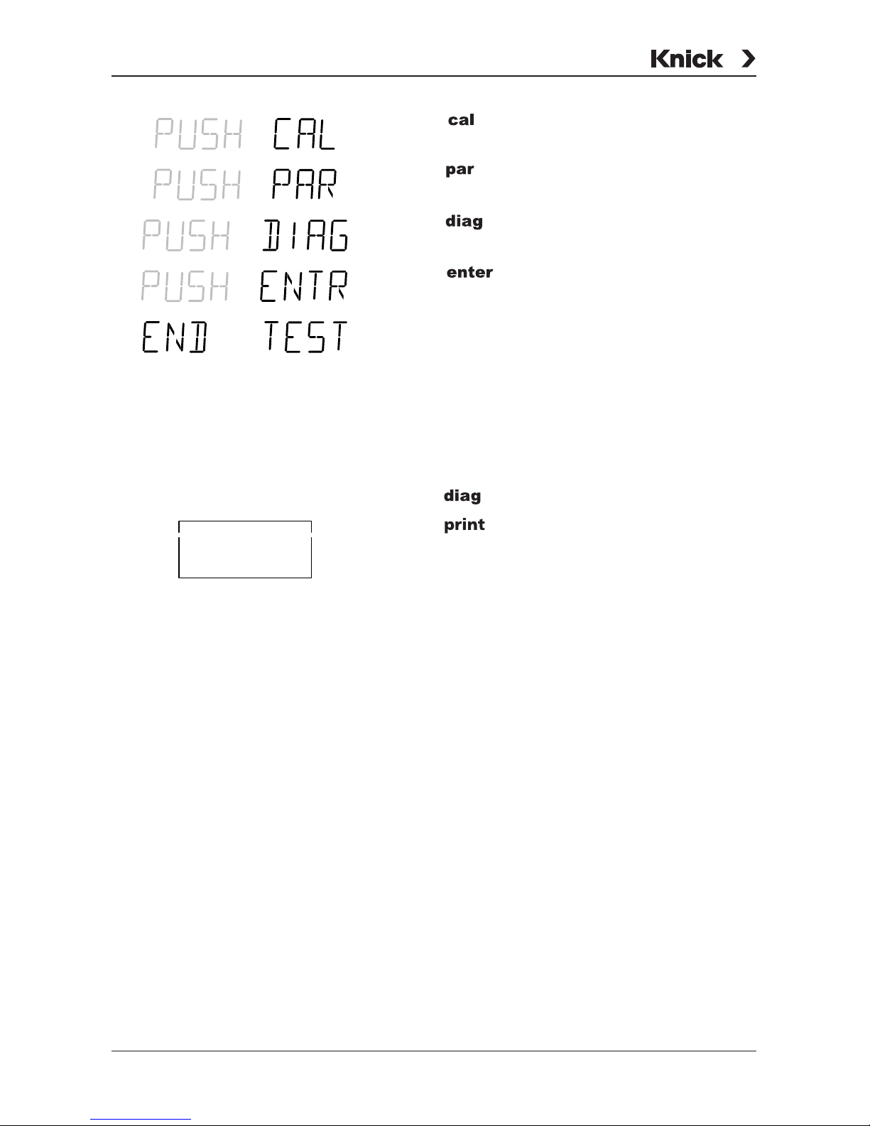
Operation 29
Press .
Press .
Press .
Press .
End of device test
Printing diagnostics record If you have connected the meter to a printer, you
can print out a record of the diagnostics.
Press to open the Diagnostics level.
Press to print out the complete diagnostics
record.
print
Page 36

765 Laboratory pH Meter
30 Operation
Trueline® recorder output
The Trueline® recorder output was developed for
the 765 Laboratory pH Meter. Trueline
®
supplies an
analog output signal without disturbing voltage
steps, but being calibrated to pH. Galvanic output
isolation is standard. Connected recorders and
data acquisition systems thus do not have to be
floating.
On the Parameter level, the output can be set for
three different input variables:
If pH has been selected as output variable, the output voltage zero is at pH 7. For meters with Option
346 (Nominal electrode zero and slope userdefined), the output voltage zero is at the selected
nominal zero point.
If the recorder output has been set for printer control, a voltage of approx. 1.5 V lies across its output.
By short-circuiting (current approx. 1.5 mA), e.g.
using a foot switch, you can print out the currently
measured values.
Do not apply an external voltage to the recorder
output. The meter might be damaged.
Input variable Output voltage
pH value 100 mV/pH
Voltage 1 mV/mV
Te mperature 10 mV/°C
Page 37

Operation 31
Serial interface
The Model 765 comes with an RS 232 interface.
The interface is user-definable for direct control of a
printer with serial input or for direct connection to a
computer. The pH meter is completely computer
controllable and all values and parameters can be
read out.
Interface parameters The RS 232 interface is user-definable for all com-
mon baud rates and data protocols.
Settings are made on the Parameter level.
• Baud rate: 600 / 1200 / 2400 / 4800 / 9600 Bd
• Data format:
• Protocol: No protocol
XON/XOFF bidirectional handshake
If not ready to accept data,
the meter transmits XOFF < 13 > H,
if ready to accept data, XON < 11 > H
Pin assignment The pH meter has a 9-pin D SUB connector (con-
nector with pin contacts). The metallic connector
shell is connected to signal ground via a capacitor
and provides EMI shielding.
Data word length Parity Stop bit
7 bits even 1
7 bits odd 1
8 bits none 1
Contact Signal Input/Output
2 (RD) Received data Input
3 (TX) Transmitted data Output
5 (SGND) Signal ground
4,6,8 Jumpered
Page 38

765 Laboratory pH Meter
32 Operation
Interface cable Knick offers as accessory:
• ZU 0245 interface cable for connecting the
pH meter to the ZU 0244 Lab Printer.
• ZU 0152 interface cable for connecting the
pH meter to a computer (PC):
Standard settings for
ZU 0244 Lab Printer
Settings on Laboratory pH Meter
Command set for the serial interface
The pH meter’s command set is divided into read
and write commands.
• Read commands start with ”R”. They read out
data from the pH meter. Read commands always
return a response. Device function is not affected.
• Write commands start with ”W”. They send com-
mands and parameters to the pH meter. A write
command modifies device settings or parameters.
The meter does not return a response. Acknowledgement of write commands can be enabled
with the ”WPMSR1” command. Then the meter
will return ”CR” (carriage return <0D> H) after
each write command.
D-SUB 9-pin socket D-SUB 9-pin socket
2 (RD) 3
3 (TD) 2
5 (SGND) 5
4 4
6 6
8 8
Connector shell (SHIELD) Connector shell
Parameter Value to be set Setting
Baud rate 4800 Bd 4800
Data format 7 data bits,
parity even
7 EV
Protocol XON/XOFF XON
Interface Printer PRNT
Page 39

Operation 33
Message terminator Message terminators for read and write
• Read: The pH meter terminates the string by ”CR”
(carriage return <0D> H).
• Write: The pH meter expects ”CR” or ”LF” (line
feed <0A> H) or any combination of these as message terminator.
Numerical parameters Format of a numerical parameter
• Mantissa:
preceded by +, –, blank or without sign
up to 14 valid digits incl. sign
Decimal point or comma floating or without
• Exponent:
”E” indicates exponent beginning
+ or – sign
1 to 3 digits
Exponent may be omitted.
Example: +1234567E–123
Exponent:
Numerical digits
Sign
Exponent
beginning
Mantissa:
Numerical digits
Sign
Reading measured values
or results
Command
Response Unit Description
RV0 ± xx.xx [pH] pH value
RV1 ± xxxxE–3 [V] Electrode
potential
RV2 ± xxx.x [°C] Pt100/Pt1000
temperature
R
VTRT xxxx [hhmm] Time: hours/
minutes
RVDRT xxxxxx [ddmmyy] Date: day/month/
year
RVTCA xxxx [h] Calibration timer
count
RVZA ± xx.xx [pH] Current
electrode zero point
RVSA ± xxxxE–3 [V/pH] Current
electrode slope
Page 40

765 Laboratory pH Meter
34 Operation
Reading error messages
List of error messages (xx):
Reading operating states
Reading Sensoface
®
states
List of Sensoface® messages (x):
Command
Response Description
RSF1 xx First error message
RSFA xx;xx;xx;... All active
error messages
List of error messages (xx):
01 pH range –2.00 to +16.00 exceeded
02 mV range -2000 to +2000 mV exceeded
03 °C range –50. to +150 °C exceeded
04 Zero range pH 6.00 to 8.00 exceeded
05 Slope range 47.0 to 67.0 mV/pH exceeded
09 Buffer cannot be identified
10 Identical buffers
20 Interface error
90 System failure
Command
Response
Description
RSP xx Operating states
00 Measuring mode
01 Parameter mode
02 Calibration mode
08 Diagnostics mode
Command
Response
Description
RSES x
Sensoface® display
RSEZS x
Sensoface
®
: zero/slope
RSETR x
Sensoface
®
: electrode response
RSERG x
Sensoface
®
: electrode impedance
RSERT x
Sensoface
®
: Drycheck
RSETC x
Sensoface
®
: Calibration timer
0
1
2
Page 41

Operation 35
Query keypad
Reading results of Knick
Fullcheck® self test
Reading calibration data
Command
Response
Description
RSK xx Query keypad
00
key
01
key
02
key
03
key
04
key
05
key
06
key
07
key
08
key
09
key
Command Re-
sponse
Unit Description
RSTET xxxx [hhmm] Last Fullcheck/
time
RSTED xxxxxx [ddmmyy] Last Fullcheck/date
RSTERR x RAM test
RSTERP x EPROM test
RSTERE x EEPROM test
RSTERA x Amplifier test
RSTERI x Impedance test
RSTERDI x Display test
RSTERKY x Keypad test
List of test results
0 ok (display test executed)
1 Test not executed
2 Defective
Command Response Unit Description
RSCPT xxxx [hhmm] Last calibration/
time
RSCPD xxxxxx [ddmmyy] Last calibration/
date
RSCPS xx Buffer set
RSCP1NB ± xx.xx [pH] Buffer 1:
nominal value
RSCP11 ± xxxxE–3 [V] Buffer 1: electrode
potential
RSCP12 ± xxx.x [°C] Buffer 1:
temperature
RSCP1TR xxxx [s] Buffer 1: response
time
Page 42

765 Laboratory pH Meter
36 Operation
Reading electrode statistics
RSCP2NB ± xx.xx [pH] Buffer 2: nominal
value
RSCP21 ± xxxxE–3 [V] Buffer 2: electrode
potential
RSCP22 ± xxx.x [°C] Buffer 2:
temperature
RSCP2TR xxxx [s] Buffer 2: response
time
Command Response Unit Description
Command
Response Unit Description
Record 3 (last calibration):
RSSTT3 xxxx [hhmm] Calibration/time
RSSTD3 xxxxxx [ddmmyy] Calibration/date
RSSTZ3 ± xx.xx [pH] Electrode zero point
RSSTS3 ± xxxxE–3 [V/pH] Electrode slope
RSSTTR3 xxxx [s] Electrode response
Record 2 (second last calibration):
RSSTT2 xxxx [hhmm] Calibration/time
RSSTD2 xxxxxx [ddmmyy] Calibration/date
RSSTZ2 ± xx.xx [pH] Electrode zero point
RSSTS2 ± xxxxE–3 [V/pH] Electrode slope
RSSTTR2 xxxx [s] Electrode response
Record 1 (third last calibration):
RSSTT1 xxxx [hhmm] Calibration/time
RSSTD1 xxxxxx [ddmmyy] Calibration/date
RSSTZ1 ± xx.xx [pH] Electrode zero point
RSSTS1 ± xxxxE–3 [V/pH] Electrode slope
RSSTTR1 xxxx [s] Electrode response
Record 0 (first calibration):
RSSTT0 xxxx [hhmm] Calibration/time
RSSTD0 xxxxxx [ddmmyy] Calibration/date
RSSTZ0 ± xx.xx [pH] Electrode zero point
RSSTS0 ± xxxxE–3 [V/pH] Electrode slope
RSSTTR0 xxxx [s]
Electrode response
Page 43

Operation 37
Reading parameters
Command Response Unit Description
RPTMMV ± xxx.x [°C] Manual temperature
RPCATI xxxx [h] Calibration timer
interval
RPINPTI xxx.x [min] Print timer interval
RPMSR x Response to
write command on/off
0 Off
1 On
RPDIE x
Sensoface
®
on/off
0 Off
1 On
RPDIDA x
Displaymatic
®
on/off
0 Off
1 On
RPAINA x Assignment for
recorder output
0 pH
1 mV
2 Te mperature
8 Input for
printer control
RPCASA xx Calibration buffer set
00 Knick technical
buffers
01 Mettler Toledo
technical buffers
02 Merck Titrisol buffers
03 Techn. buffers to
DIN 19 276
04 Standard buffers to
DIN 19 266
05 Merck Titrisol buffers
06 Merck buffers ready
to use
07 Ciba (94)
08 customer specific
09 customer specific
10
Mettler Toledo (USA)
Page 44

765 Laboratory pH Meter
38 Operation
Only for meters
with Option 346:
Only for meters with Option 346: Nominal electrode
zero and slope user-defined
Command
Response Unit Description
RPCA0NZ ± xx.xx [pH] Nomminal zero
RPCA0NS ± xxxxE–3 [V/pH] Nominal slope
RPCA0U ± xxxxE–3 [V] V iso isothermal
potential
Page 45

Operation 39
Writing parameters
Command Parameter Unit Description
WPTMMV Num. par. [°C] Manual temperature
WPCATI Num. par. [h] Calibration timer
interval
WPINPTI Num. par. [min] Print timer interval
WPMSR x Response to
write command on/off
0 Off
1 On
WPDIE x
Sensoface
®
on/off
0 Off
1 On
WPDIDA x
Displaymatic
®
on/off
0 Off
1 On
WPAINA x Assignment of
recorder output
0 pH
1 mV
2 Te mperature
8 Input for
printer control
WPCASA xx Calibration buffer set
00 Knick techn. buffers
01 Mettler Toledo
technical buffers
02 Merck Titrisol buffers
03 Techn. buffers to
DIN 19 276
04 Standard buffers to
DIN 19 266
05 Merck Titrisol buffers
06 Merck buffers
ready to use
07 Ciba (94)
08 customer specific
09 customer specific
10
Mettler Toledo (USA)
Page 46

765 Laboratory pH Meter
40 Operation
Only for meters
with Option 346:
Nominal electrode zero and slope are set as follows:
Control commands
Reading device description
Command Parameter Unit Description
WPCA0NZ Num. par. [pH] Nominal
zero point
WPCA0NS Num. par. [V/pH] Nominal
slope
WPCA0U Num. par. [V]
V iso isothermal
potential
Command Description
WCIU Initialize device
WCTEA Perform Fullcheck
WCRTT [hhmm] Set time
WCRTD [ddmmyy] Set date
WCOM00 Switch to measuring mode
WCCASTI Set first calibration
(only for Option 347)
WCCAA1 Start calibration with 1st buffer
WCCAA2 Start calibration with 2nd buffer
WCDISLA0 Left display, indicate pH
WCDISLA1 Left display, indicate mV
WCDISLA2 Left display, indicate temperature
WCDISLATRT Left display, indicate time
WCDISRA0 Right display, indicate pH
WCDISRA1 Right display, indicate mV
WCDISRA2 Right display, indicate
temperature
WCDISRATRT
Right display, indicate time
Command
Response Description
RDMF KNICK Manufacturer
RDUN 765 Model name
RDUS xxxxxx Serial number
RDUV xx;xx Software/hardware version
RDUP xxx;xxx;xxx
Options
Page 47
Operation 41
3 Troubleshooting
Error messages
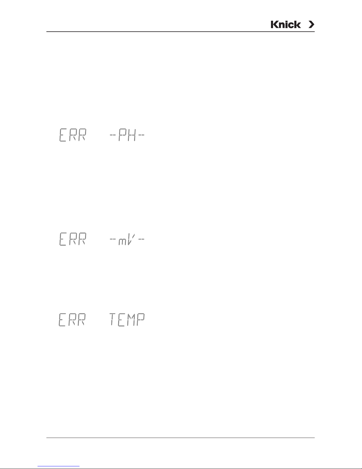
Range exceeded If a measured value is out of range, an error mes-
sage is displayed instead of the value measured.
The measured pH value is
< –2 or > +16.
Possible causes:
• Electrode defective
• Too little electrolyte in electrode
• Electrode not connected
• Break in electrode cable
• Incorrect electrode connected,
e.g. ORP electrode
The measured electrode potential is
< –1999 mV or > +1999 mV.
Possible causes:
• Electrode defective
• Electrode not connected
• Break in electrode cable
The measured temperature is
< –50 °C or > +150 °C
Possible causes:
• Temperature probe defective
Page 48
765 Laboratory pH Meter
42 Operation
Calibration error messages When errors occur during calibration or when the
determined electrode data are out of range, an
error message will be displayed.
The meter cannot identify the buffer solution in use.
This message is only momentarily displayed during
calibration.
Possible causes:
• Buffer solution does not belong to
the selected buffer set
• Electrode defective
• Electrode not connected
• Break in electrode cable
• Wrong buffer temperature selected
(for manual temperature compensation)
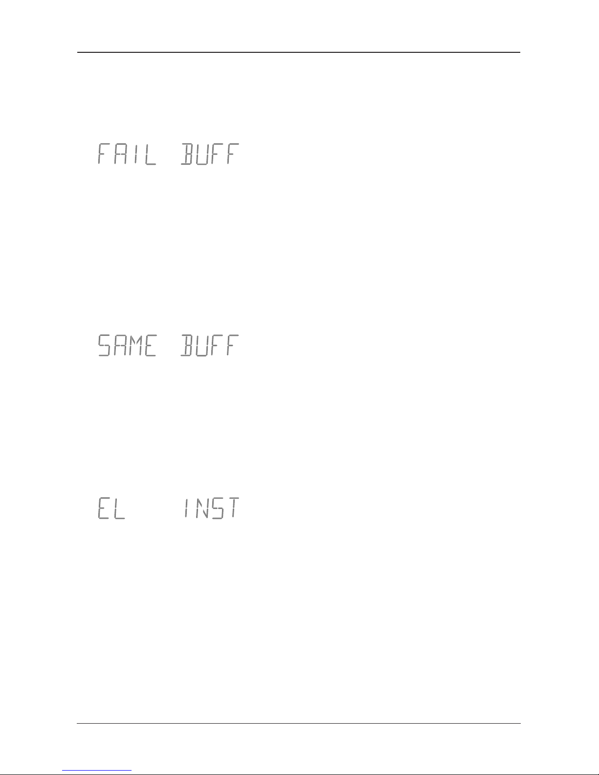
The meter identified two identical buffer solutions.
This message is only momentarily displayed during
calibration.
Possible causes:
• Same or similar buffer solution used for second
calibration step
• Buffer solutions contaminated
• Electrode defective
• Electrode not connected
• Break in electrode cable
Calibration was canceled after approx. 2 minutes,
because the electrode drift was too large. This message is only momentarily displayed during calibration.
Possible causes:
• Electrode defective
• No electrolyte in the electrode
• Electrode cable not sufficiently shielded
or defective
• Strong electric fields influence the
measurement
• Major temperature fluctuation of the buffer
solution
• No buffer solution or extremely diluted
Page 49
Operation 43
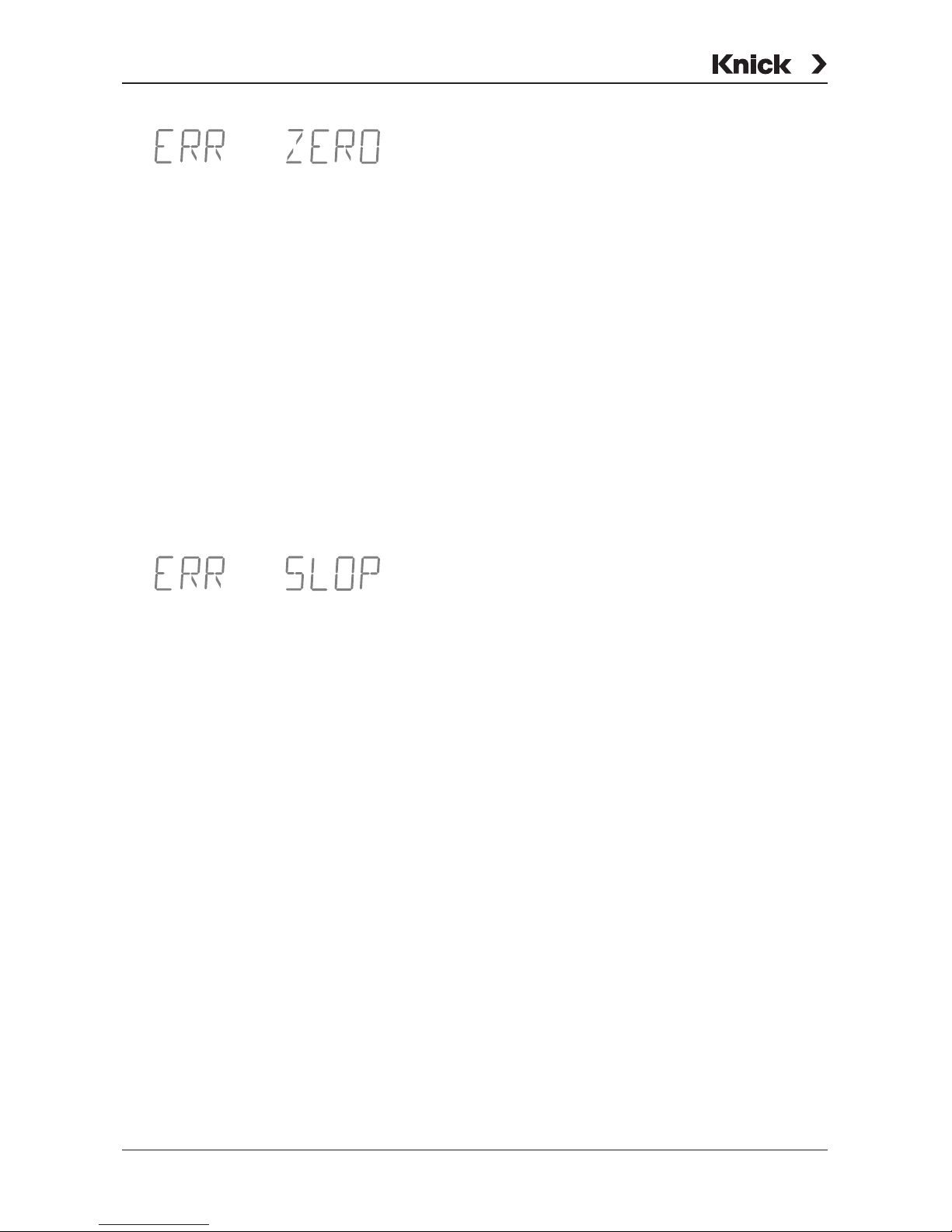
The electrode zero determined during calibration is
out of range. Electrode zero is < pH 6 or > pH 8
(for Option 346: at ± 1 pH unit from nominal zero)
This message is displayed in measuring mode after
a calibration. It can only be reset by a new calibration.
Possible causes:
• Electrode "worn out"
• Buffer solutions contaminated
• Temperature probe not immersed in buffer
solution (for automatic temperature
compensation)
• Wrong buffer temperature selected
(for manual temperature compensation)
• Used electrode has different nominal
zero point
The electrode slope determined during calibration
is out of range.
The electrode slope is < 47.0 mV/pH or
> 61.0 mV/pH (for Option 346: at ± 7 mV/pH from
nominal slope). This message is displayed in measuring mode after a calibration. It can only be reset
by a new calibration.
Possible causes:
• Electrode ”worn out”
• Buffer solutions contaminated
• Temperature probe not immersed in buffer
solution (for automatic temperature
compensation)
• Wrong buffer temperature selected
(for manual temperature compensation)
• Used electrode has different nominal
slope
Page 50
765 Laboratory pH Meter
44 Operation
Interface error message When errors occur during transmission via inter-
face, an error message is displayed.
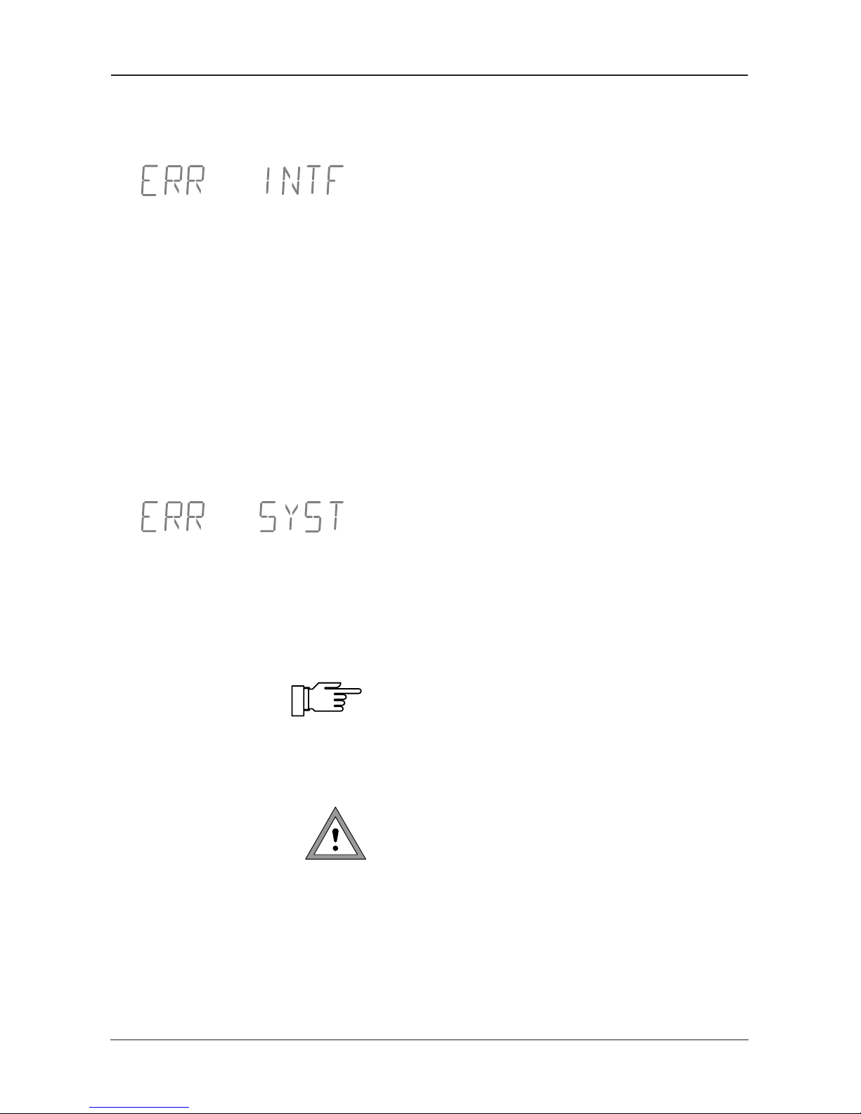
The meter has received an invalid interface command.
Possible causes:
• Syntax error in interface command
• Too many characters in one string
• No valid message terminator
• Wrong transmission rate (baud rate) selected
• Wrong data word length or parity selected
• Wrong transmission protocol (handshake)
selected
• Interference during transmission
System error message When a system error is found during the self test,
an error message is displayed.
Error in the configuration or calibration data or in
the factory settings
Possible causes:
• Clock defective
• EPROM, EEPROM or RAM defective
• Error in factory settings
This error message normally should not occur, as
the data are protected from loss by multiple safety
functions. Should this error message nevertheless
occur, there is no remedy. The meter must be recalibrated at the factory.
Opening the meter exposes live parts. Therefore, it
shall not be opened. If a repair should be required,
return the meter to our factory.
Page 51

Appendix 45
Appendix
Product line
Ref. No.
Device
pH meter with power cord, without
electrode
765
Accessories
Attachable stand, for ZU 6955 immersion
stirrer and three sensors, directly connected
to pH meter
ZU 6954
Immersion stirrer, powered via
ZU 6956 power pack
ZU 6955
Power pack for immersion stirrer ZU 6956
Lab Printer ZU 0244
Interface cable for connecting the Model 765
to a printer (ZU 0244)
ZU 0245
Interface cable for connecting the Model 765
to a computer (special EMC cable)
ZU 0152
Sensors and
buffer solutions
Combination pH/Pt 1000 electrode
(glass, with integrated Pt 1000 temp probe
0 to 80 °C, pH 0 to 14)
SE 100
Combination pH electrode
(glass, without temperature probe,
0 to 100 °C, pH 0 to 14)
SE 103
Pt 1000 temperature probe, for fast response
temperature measurements
(stainless steel, -10 to +100 °C)
ZU 6959
Calibration buffer set with Knick technical
buffer solutions (250 ml each of pH 4, pH 7,
pH 9 and KCl solution)
ZU 0261
Calibration buffer set with standard buffer
solutions to DIN 19 266 and NIST (NBS)
(250 ml each of pH 4, pH 7 and KCl solution)
ZU 6941
Options
Power supply 115 V AC 363
Nominal electrode zero point and
slope user-defined
346
Page 52

765 Laboratory pH Meter
46 Appendix
Specifications
Ranges pH: –2.00 to +16.00
mV: –1999 to +1999
°C: –50.0 to +150.0
Display Alphanumeric, 2 x 4 digits,
14-segment LED,
Character height 13 mm
Parameters: pH/mV/°C/time
3 status indicators for electrode condition
Measuring cycle Approx. 1/sec
Accuracy
*
* ± 1 count
pH: < 0.01
mV: < 0.1 % ± 0.3 mV
°C: < 0.3 K
Input DIN 19 262
Input resistance
> 1 * 10
12
Ohms
Input current
< 1 * 10
–12
A (20°C)
**
** 45°C: factor 10
Temperature
coefficient
< 0.1 count/K
Electrode
standardization
Calimatic
®
automatic calibration
and buffer recognition
(German patent 29 37 227)
For buffer tables, see Apppendix
Calibration ranges:
Zero: pH 6 to 8
Slope: 47 to 61 mV/pH
(25°C)
(Option 346)
Nominal zero / slope / V iso
***
*** User-defined
Zero: pH 0 to 14
Slope: 25 to 61 mV/pH
V iso: –500 to +500 mV
Page 53

Appendix 47
Electrode
monitoring
Sensoface
®
:
Evaluation of zero point, slope,
response time and impedance of
electrode, and of calibration interval.
Electrode condition displayed as
good/average/poor, can be disabled
Knick Drycheck
®
:
Monitors electrode impedance for
dry-out, glass breakage and defective connections, also in standby
mode
Calibration timer monitors a preset
calibration interval
Knick Fullcheck
®
device self-test
Test of complete measurement electronics including recorder output,
segment and keypad test in Diagnostics mode,
automatic short check at power-on
Records Parameter record
Calibration record
Diagnostics record
Records for QM documentation to
ISO 9000 and GLP
*
,
retrievable via interface (printer)
or display
* Good Laboratory Practice
Displaymatic
®
Digit suppression according to signal
change, can be disabled
Te mperature
compensation
Pt 100 / Pt 1000, automatic selection
Manual: –50.0 to +150 °C
Dead stop current -10 µA
Tr ueline
®
recorder output
Galvanically isolated,
pH compensated
mV: 1 mV/mV
pH: 100 mV/pH
°C: 10 mV/°C
Isolation voltage: 40 V DC,
20 V AC
Page 54

765 Laboratory pH Meter
48 Appendix
Remote interface RS 232 without control lines, galvani-
cally isolated, user defined as
printer or computer interface
Baud rate: 600/1200/2400/4800/
9600
*
* User-defined
Data formats: 7 bits even/odd
*
8 bits without parity *
Protocol: None, XON/XOFF *
Stop bits: 1
Isolation
voltage:
40 V DC, 20 V AC
Printer control for standard printer with serial port,
printing at keystroke or via print interval
timer 0.1 to 999.9 min
Clock Clock with date, self-contained
Calibration data
storage
Automatic storage of calibration data,
self-contained
Data retention Parameters,
statistics and
factory settings: >10 years
(EEPROM)
Clock: Reserve power>1year
(battery-backed)
Electrode
statistics
Storage of zero and slope of first calibration, as well as data of last three
calibrations with time and date, selfcontained, output via interface to
printer or computer.
EMC 2004/108/EC
Emitted interference: Class B
Immunity to interference: Industry
Standards:
DIN EN 61326 -1
(VDE 0843 Part 20-1): 2006-10
DIN EN 61326-2-3
(VDE 0843 Part 20-2-3): 2007-05
Low-voltage
directive
2006/95/EC
Standards:
EN 61010-1: 2001
Operating temp 0 to +45 °C
Storage and
transport temp
–20 to +70 °C
Page 55

Appendix 49
Buffer tables
Buffer set 00 Knick technical buffers
Power supply 230 V –15 % +10 %, 48 to 62 Hz,
< 10 VA, Class II
Option 363: 115 V AC
Enclosure Glass reinforced polyamide 12, stain-
less steel cover, IP 54 protection, ready
for connection of ZU 6954 attachment
stand
Dimensions 244 x 95 x 255 mm (w x h x d)
Weight
Approx. 2 kg
°C pH
0 2.03 4.01 7.12 9.52
5 2.02 4.01 7.09 9.45
10 2.01 4.00 7.06 9.38
15 2.00 4.00 7.04 9.32
20 2.00 4.00 7.02 9.26
25 2.00 4.01 7.00 9.21
30 1.99 4.01 6.99 9.16
35 1.99 4.02 6.98 9.11
40 1.98 4.03 6.97 9.06
45 1.98 4.04 6.97 9.03
50 1.98 4.06 6.97 8.99
55 1.98 4.08 6.98 8.96
60 1.98 4.10 6.98 8.93
65 1.99 4.13 6.99 8.90
70 1.99 4.16 7.00 8.88
75 2.00 4.19 7.02 8.85
80 2.00 4.22 7.04 8.83
85 2.00 4.26 7.06 8.81
90 2.00 4.30 7.09 8.79
95 2.00 4.35 7.12 8.77
Page 56

765 Laboratory pH Meter
50 Appendix
Buffer set 01 Mettler-Toledo technical buffers
(correspond to Ingold technical buffers)
Buffer set 02 Merck Titrisol buffers and ready-to-use buffer
solutions, Riedel Fixanal buffers and ready-to-use
buffer solutions
°C pH
0 2.03 4.01 7.12 9.52
5 2.02 4.01 7.09 9.45
10 2.01 4.00 7.06 9.38
15 2.00 4.00 7.04 9.32
20 2.00 4.00 7.02 9.26
25 2.00 4.01 7.00 9.21
30 1.99 4.01 6.99 9.16
35 1.99 4.02 6.98 9.11
40 1.98 4.03 6.97 9.06
45 1.98 4.04 6.97 9.03
50 1.98 4.06 6.97 8.99
55 1.98 4.08 6.98 8.96
60 1.98 4.10 6.98 8.93
65 1.99 4.13 6.99 8.90
70 1.99 4.16 7.00 8.88
75 2.00 4.19 7.02 8.85
80 2.00 4.22 7.04 8.83
85 2.00 4.26 7.06 8.81
90 2.00 4.30 7.09 8.79
95 2.00 4.35 7.12 8.77
°C pH
0 2.01 4.05 7.13 9.24 12.58
5 2.01 4.04 7.07 9.16 12.41
10 2.01 4.02 7.05 9.11 12.26
15 2.00 4.01 7.02 9.05 12.10
20 2.00 4.00 7.00 9.00 12.00
25 2.00 4.01 6.98 8.95 11.88
30 2.00 4.01 6.98 8.91 11.72
35 2.00 4.01 6.96 8.88 11.67
40 2.00 4.01 6.95 8.85 11.54
45 2.00 4.01 6.95 8.82 11.44
50 2.00 4.00 6.95 8.79 11.33
55 2.00 4.00 6.95 8.76 11.19
60 2.00 4.00 6.96 8.73 11.04
65 2.00 4.00 6.96 8.72 10.97
70 2.01 4.00 6.96 8.70 10.90
75 2.01 4.00 6.96 8.68 10.80
80 2.01 4.00 6.97 8.66 10.70
85 2.01 4.00 6.98 8.65 10.59
90 2.01 4.00 7.00 8.64 10.48
95 2.01 4.00 7.02 8.64 10.37
Page 57

Appendix 51
Buffer set 03 Technical buffer solutions to DIN 19 267
* Extrapolated
Buffer set 04 Standard buffer solutions to DIN 19 266 and NIST
(NBS)
* Extrapolated
°C pH
0 1.08 3.14* 4.67 6.89 9.48 13.95*
5 1.08 3.12* 4.67 6.87 9.43 13.63*
10 1.09 3.10 4.66 6.84 9.37 13.37
15 1.09 3.08 4.66 6.82 9.32 13.16
20 1.09 3.07 4.65 6.80 9.27 12.96
25 1.09 3.06 4.65 6.79 9.23 12.75
30 1.10 3.05 4.65 6.78 9.18 12.61
35 1.10 3.05 4.65 6.77 9.13 12.45
40 1.10 3.04 4.66 6.76 9.09 12.29
45 1.10 3.04 4.67 6.76 9.04 12.09
50 1.11 3.04 4.68 6.76 9.00 11.98
55 1.11 3.04 4.69 6.76 8.96 11.79
60 1.11 3.04 4.70 6.76 8.92 11.69
65 1.11 3.04 4.71 6.76 8.90 11.56
70 1.11 3.04 4.72 6.76 8.88 11.43
75 1.11 3.04 4.73 6.77 8.86 11.31
80 1.12 3.05 4.75 6.78 8.85 11.19
85 1.12 3.06 4.77 6.79 8.83 11.09
90 1.13 3.07 4.79 6.80 8.82 10.99
95 1.13* 3.08* 4.82* 6.81* 8.81* 10.89*
°C pH
0 1.666 4.010 6.948 9.464 13.423
5 1.668 4.004 6.951 9.395 13.207
10 1.670 4.000 6.923 9.332 13.003
15 1.672 3.999 6.900 9.276 12.810
20 1.675 4.001 6.881 9.225 12.627
25 1.679 4.006 6.865 9.180 12.454
30 1.683 4.012 6.853 9.139 12.289
35 1.688 4.021 6.844 9.102 12.133
40 1.694 4.031 6.838 9.068 11.984
45 1.700 4.043 6.834 9.038 11.841
50 1.707 4.057 6.833 9.011 11.705
55 1.715 4.071 6.834 8.985 11.574
60 1.723 4.087 6.836 8.962 11.449
65 1.733 4.109 6.841 8.942 11.330*
70 1.743 4.126 6.845 8.921 11.210*
75 1.755 4.145 6.852 8.903 11.100*
80 1.766 4.164 6.859 8.885 10.990*
85 1.779 4.185 6.868 8.868 10.890*
90 1.792 4.205 6.877 8.850 10.790*
95 1.806 4.227 6.886 8.833 10.690*
Page 58

765 Laboratory pH Meter
52 Appendix
Buffer set 05 Merck Titrisol buffers and ready-to-use buffer
solutions, Riedel Fixanal buffers and ready-to-use
buffer solutions
Buffer set 06 Merck ready-to-use buffer solutions
* Values to DIN 19 267
(not defined by Merck)
°C pH
0 0.96 3.05 6.04 8.15 10.26 13.80
5 0.99 3.05 6.02 8.10 10.17 13.59
10 0.99 3.03 6.01 8.07 10.11 13.37
15 0.99 3.01 6.00 8.04 10.05 13.18
20 1.00 3.00 6.00 8.00 10.00 13.00
25 1.01 3.00 6.02 7.96 9.94 12.83
30 1.01 3.00 6.03 7.94 9.89 12.67
35 1.01 3.00 6.03 7.92 9.84 12.59
40 1.01 2.98 6.04 7.90 9.82 12.41
45 1.01 2.98 6.05 7.88 9.78 12.28
50 1.01 2.97 6.06 7.85 9.74 12.15
55 1.02 2.97 6.08 7.84 9.71 11.95
60 1.02 2.97 6.10 7.83 9.67 11.75
65 1.02 2.97 6.11 7.82 9.65 11.68
70 1.02 2.97 6.12 7.80 9.62 11.61
75 1.02 2.97 6.14 7.79 9.59 11.50
80 1.02 2.97 6.17 7.78 9.55 11.39
85 1.02 2.97 6.20 7.77 9.52 11.27
90 1.02 2.96 6.24 7.75 9.49 11.15
95 1.02 2.96 6.28 7.74 9.46 11.03
°C pH
0 4.68 6.98 9.46
5 4.68 6.95 9.40
10 4.67 6.92 9.33
15 4.67 6.90 9.28
20 4.66 6.88 9.22
25 4.66 6.86 9.18
30 4.66 6.86 9.14
35 4.66 6.85 9.10
40 4.67 6.84 9.07
45 4.68 6.84 9.04
50 4.68 6.84 9.01
55 4.69 6.84 8.99
60 4.70 6.84 8.96
65 4.71* 6.84 8.95
70 4.72* 6.84 8.93
75 4.74* 6.85 8.91
80 4.75* 6.86 8.89
85 4.77* 6.87 8.87
90 4.79* 6.88 8.85
95 4.81* 6.89 8.83
Page 59

Appendix 53
Buffer set 07 Ciba (94)
Nominal value: 2.06, 4.00, 7.00, 10.00
* Extrapolated
5
Interpolated
Buffer set 10 Mettler-Toledo (USA)
* Extrapolated
°C pH
0 2.04 4.00 7.10 10.30
5 2.09 4.02 7.08 10.21
10 2.07 4.00 7.05 10.14
15 2.08 4.00 7.02 10.06
20 2.09 4.01 6.98 9.99
25 2.08 4.02 6.98 9.95
30 2.06 4.00 6.96 9.89
35 2.06 4.01 6.95 9.85
40 2.07 4.02 6.94 9.81
45 2.06 4.03 6.93 9.77
50 2.06 4.04 6.93 9.73
55 2.05 4.05 6.91 9.68
60 2.08 4.10 6.93 9.66
65 2.07
5
4.10
5
6.92
5
9.61
5
70 2.07 4.11 6.92 9.57
75 2.04
5
4.13
5
6.92
5
9.54
5
80 2.02 4.15 6.93 9.52
85 2.03 4.17
5
6.95 9.47
5
90 2.04 4.20 6.97 9.43
95 2.05* 4.225* 6.99* 9.385*
°C pH
0 4.00 7.12 10.32
5 4.00 7.09 10.25
10 4.00 7.06 10.18
15 4.00 7.04 10.12
20 4.00 7.02 10.06
25 4.00 7.00 10.01
30 4.01 6.99 9.97
35 4.02 6.98 9.93
40 4.03 6.98 9.89
45 4.04 6.97 9.86
50 4.06 6.97 9.83
55 4.06* 6.97* 9.83*
60 4.06* 6.97* 9.83*
65 4.06* 6.97* 9.83*
70 4.06* 6.97* 9.83*
75 4.06* 6.97* 9.83*
80 4.06* 6.97* 9.83*
85 4.06* 6.97* 9.83*
90 4.06* 6.97* 9.83*
95 4.06* 6.97* 9.83*
Page 60

765 Laboratory pH Meter
54 Appendix
Page 61

Glossary 55
Glossary
Buffer set Contains selected buffer solutions which can be
used for automatic calibration with the Knick Calimatic
®
. The buffer set must be selected prior to the
first calibration.
Buffer solution Solution with an exactly defined pH value for cali-
brating a pH meter.
cal Key for activating the Calibration level.
Cal timer Counts the time passed since the last calibration.
Calibration Adjustment of the pH meter to the current electrode
characteristics. Zero and slope are adjusted.
Calibration buffer set See buffer set.
Calibration level On the Calibration level the meter is adjusted for
the connected electrode (calibration). You can conduct either a one or a two-point calibration.
Calibration record Printout of all relevant data of the last calibration for
documentation to GLP. Start printout by pressing
and .
Calimatic
®
Automatic buffer recognition. Prior to first calibration, the used buffer set must be activated once on
the Parameter level. The patented Calimatic
®
then
automatically recognizes the buffer solution used
during calibration.
Combination electrode Combination of glass and reference electrode in
one body.
diag Key for activating the Diagnostics level.
Diagnostics level Display of criteria for Sensoface
®
display, all relevant electrode data, electrode statistics and activation of Fullcheck
®
device self test.
Page 62

765 Laboratory pH Meter
56 Glossary
Diagnostics record Printout of criteria for Sensoface
®
display, all relevant electrode data, electrode statistics and results
of Fullcheck
®
device self test for documentation to
GLP. Start printout by pressing and .
Electrode slope Specified in mV/pH. It is different for each electrode
and changes with age and wear.
Electrode statistics The electrode statistics provide the electrode data
of the last three calibrations and the first calibration.
Electrode zero point Voltage output by a pH electrode at pH 7 (for devi-
ating nominal zero point at correspondingly different pH value). It is different for each electrode and
changes with age and wear.
enter Key for confirming entries.
First calibration During first calibration, the electrode data are
stored as reference values for electrode statistics.
GLP Good Laboratory Practice: Guidelines for perfor-
mance and documentation of measurements in the
laboratory.
Isothermal potential The isothermal potential is the potential at which
the calibration curves for different temperatures intersect. Ideally, this is at 0 mV.
Knick Drycheck
®
Knick Drycheck® monitors the electrodes and alerts
for dry out, glass breakage and defective connections.
Knick Fullcheck
®
Device self test, checks complete measuring circuitry, signal processing, memories, display, and
keypad.
meas This key allows return to measuring mode from all
other levels.
Measuring mode When no function level is activated, the meter is in
measuring mode. The two displays indicate the respectively assigned variable.
Page 63

Glossary 57
Nominal electrode
zero point
Nominal value of electrode zero point. For commercial electrodes, the nominal electrode zero point is
at pH 7.
Special electrodes can have a different zero point.
If you want to use such an electrode, your meter
must be equipped with Option 346.
Nominal electrode slope Nominal value of electrode slope. For commercial
eletrodes, the nominal slope is 59.2 mV/pH at
25 °C.
Special electrodes, such as Pfaudler or Antimony
probes, can have a different slope. If you want to
use such an electrode, your meter must be
equipped with Option 346.
One-point calibration Calibration that only takes account of the electrode
zero point. The old slope value is retained. Only
one buffer solution is required for a one-point calibration.
par Key for activating the Parameter level.
Parameter level The Parameter level is divided into two submenus.
VIEW menu and EDIT menu. The VIEW menu allows to display all parameters without editing them.
The EDIT menu allows to view and edit all parameters.
Parameter record Printout of all stored parameter settings for docu-
mentation to GLP. Start printout by pressing
and .
pH electrode A pH electrode system consists of a glass and a ref-
erence electrode. If they are combined in one
body, they are referred to as combination electrode.
Print interval timer The print interval timer allows to preset an interval
for printout of currently measured values with time
and date.
Response time Time from the start of a calibration step to the sta-
bilization of the electrode potential.
Page 64

765 Laboratory pH Meter
58 Glossary
Sensoface
®
Automatic electrode monitoring. The Sensoface®
display provides information on the electrode condition. It evaluates zero point, slope, response time,
impedance and dry-out of the electrode and the cal
timer count.
Slope See Electrode slope.
Trueline
®
The Trueline® recorder output provides a pH-calibrated analog output signal, without disturbing voltage steps.
Two-point calibration Calibration that takes account of zero point and
slope of the electrode. Two buffer solutions are required for two-point calibration.
Zero point See electrode zero point.
Page 65

Index
B
Buffer set 14
Buffer tables 49
C
Calibration error messages 42
Calibration level 18
Calibration record 20
Calibration timer
Setting 15
Commissioning 6
Connection
Double platinum electrode 7
Electrode 7
Mains 6
Polarization current 7
D
Device self-test 27
Diagnostics
Diagnostics level 21
Electrode Data menu 21
Knick Fullcheck menu 21
Sensoface menu 21, 22
Diagnostics record 29
Displaymatic 13
Double platinum electrode 7
E
EDIT menu 10
Electrode connection 6
Electrode Data menu 25
Electrode statistics 25
Error messages 41
List of 34
F
First calibration
Activation 15
I
Interface cable 32
K
Keypad 3
L
Lab printer, ZU 0244
Standard settings 32
M
Mains supply 6
Measuring mode 9
Menu structure 5
N
Nominal electrode slope (setting for
Option 346) 13
Nominal electrode zero (setting for
Option 346) 13
O
One-point calibration 19
Operation
Meter design 2
Option 346 13
P
Package contents 1
Parameter record 12
Parameter setting
Activation 10
EDIT menu 10
Example 11
VIEW menu 10
Polarization current 7
Print interval timer 16
Printer, ZU 0244
Standard settings 32
Printing
Calibration record 20
Diagnostics record 29
Measured values 9
Parameter record 12
Product line 45
R
Recorder output 30
Setting 15
Remote interface
Cable 32
Commands 32
Page 66

Parameters 31
Pin assignment 31
Printer 32
RS 232 interface 31
S
Safety information III
Sensoface 5
Sensoface menu 21, 22
Sensor monitoring 5
Setting
Remote interface 16
Short check (at power-on) 8
Short description 1
Specifications 46
Standby mode 8
T
Trueline recorder output 30
Two-point calibration 19
V
VIEW menu 10
 Loading...