


KNF 308934-308937 09/18
OEM
N 2400.15
TRANSLATION OF ORIGINAL OPERATING AND
ENGLISH
INSTALLATION INSTRUCTIONS
DIAPHRAGM PUMP
Note!
Before operating the pump and the accessories, please read the operating instructions and pay attention to
the safety precautions!

KNF Neuberger GmbH
Alter Weg 3
79112 Freiburg
Germany
Phone +49-(0)7664-5909-0
Fax +49-(0)7664-5909-99
E-mail: info@knf.de
www.knf.de
Contents Page
About this document ................................................................... 3
1.
2. Use .............................................................................................. 5
3. Safety .......................................................................................... 7
4. Technical Data .......................................................................... 10
5. Design and function .................................................................. 13
6. Transportation ........................................................................... 15
7. Installation and connection ....................................................... 18
8. Operation .................................................................................. 25
9. Servicing ................................................................................... 27
10. Troubleshooting ........................................................................ 33
11. Spare parts and accessories .................................................... 35
12. Returns ..................................................................................... 36
13. Health and safety clearance and decontamination form .......... 37

Diaphragm pump N 2400.15 About this document
Compliance with the Operating and Installation Instructions is
essential for the safe and reliable operat
ure to do so many results in severe or potentially life
threatening injury and/or serious damage.
A danger is located here.
Possible consequences of a failure to observe the
warning are
Warning, indicates the danger level.
Signal word
Meaning
Consequences if not observed
DANGER
warns of immedi-
Death or serious injuries and/or
quence.
WARNING
warns of possible
Death or serious injuries and/or
CAUTION
warns of a possi-
Minor injuries or damage are
Project pump
1. About this document
1.1. Using the Operating and Installation
Instructions
The Operating and Installation Instructions are part of the pump.
In several Chapters of these Operating and Installation Instruc-
tions there will be referred to the Operating Instruction of the
motor manufacturer. It is attached to these Operating and Installation Instruction.
Always keep the Operating and Installation Instructions handy
in the work area.
Pass on the Operating and Instal lat ion Instruc ti ons to the next
owner.
Customer-specific project pumps (pump models which begin with
“PJ” or “PM”) may differ from the Operating and Installation Instructions.
For project pumps, also observe the agreed upon specifica-
tions.
ion of the pump. Fail-
-
1.2. Symbols and markings
Warning
WARNING
Measures for avoiding the danger and its conse-
quences are specified here.
Danger levels
specified here. The signal word, e.g.
Tab. 1
Original-Operating and Installation Instructions, english, KNF 308934-308937 09/18 3
ate danger
danger
bly dangerous
situation
serious damage are the conse-
serious damage are possible.
possible.

About this document Diaphragm pump N 2400.15
This symbol refers to important inform ation.
Other information and symbols
An activity to be carried out (a step) is specified here.
1. The first step of an activity to be carried out is specified here.
Additional, consecutively numbered steps follow.
4 Translation of original Operating and Installation Instructions, english, KNF 308 934-308937 09/18

Diaphragm pump N 2400.15 Use
Operating parameter and
Requirements for
Frequency converter
2. Use
2.1. Proper use
The pumps are exclusively intended for transferring gases and
vapors.
Owner’s responsibility
Only install and operate the pumps under the operating parameters
conditions
and conditions described in Chapter 4. Technical Data.
Protect the compressors with a pressure relief device between the
pressure side of the compressor and the first shut-off valve.
Only complete pumps may be taken into service.
Make sure that the installation location is dry and the pump is pro-
tected against rain, splash, hose and drip water as well as other
pollutions.
The gas-tightness of the connections between the application
pipes and the pump (or the pump connection) must be checked
regularly; with leaky connections, there is a danger that hazardous
gases or vapors may escape from the pump system.
transferred medium
Before using a medium, check whether the medium can be transferred danger-free in the specific application case.
Before using a medium, check the compatibility of the components
in contact with the medium (see 4 Technical Data) with the medium.
Only transfer gases which remain stable under the pressures and
temperatures occurring in the pump.
The pumps are provided for the operation with frequency converter
-1
in the speed range 500 – 1500 min
(60 Hz) respectively (see Chapter 7.2).
(50 Hz) or 600 – 1800 min
-1
Translation of original Operating and Installation Instructions, english, KNF 308 934-308937 09/18 5

Use Diaphragm pump N 2400.15
2.2. Improper use
The pumps may not be operated in an explosive atmosphere.
The pumps are not suitable for transferring:
Dusts
Liquids
Aerosol
Biological and microbiological substances
Fuel
Explosive and combustible materials
Fibers
Oxidizing agent
Foodstuffs.
Pumps designed to create either a vacuum or an overpressure
must not be used for these two purposes simultaneously.
An overpressure must not be applied to the suction side of the
pump.
6 Translation of original Operating and Installation Instructions, english, KNF 308 934-308937 09/18

Diaphragm pump N 2400.15 Safety
Note the safety precautions in chapters 7. Installation and connection
Personnel
Working in a safety
Handling dangerous media
Handling combustible media
3. Safety
The pumps are built according to the generally recognized rules of
the technology and in accordance with the occupat io na l saf et y and
accident prevention regulations. Nevertheless, dangers can result
during their use which lead to injuries to the user or others, or to
damage to the pump or other property.
Only use the pumps when they are in a good technical and proper
working order, in accordance with their intended use, observing the
safety advice within the Operating and Installation Instructions, at
all times.
Components connected to the pump must be designed to withstand the pneumatic performance of the pump.
Take care that safety regulations are observed when connecting
the pump to the electricity supply.
Make sure that only trained and instructed personnel or specially
trained personnel work on the pumps. This especially applies to
assembly, connection and servicing work.
Make sure that the personnel has read and understood the Operating and Installation Instructions, and in particular the “Safety” chapter.
, and 8. Operation.
conscious manner
Observe the accident prevention and safety regulations when performing any work on the pump and during operation.
Ensure that the pump is separated from the mains and is deenergized.
The pump heads heat up during operation – avoid contact with
them.
Make sure that there are no hazards due to flow with open gas
connections, noises or hot gases.
Ensure that an EMC-compatible installation of the pump is ensured
at all times and that this cannot lead to a hazardous situation.
When transferring dangerous media, observe the safety regulations when handling these media.
If the diaphragm ruptures, the transferred medium will mix with the
air in the environment.
Take all necessary care to prevent this leading to a dangerous
situation.
Be aware that the pumps are not designed to be explosion-proof.
Make sure the temperature of the medium is always sufficiently
below the ignition temperature of the medium, to avoid ignition or
explosion. This also applies for unusual operational situations.
Note that the temperature of the medium increases when the pump
compresses the medium (compressor operation).
Translation of original Operating and Installation Instructions, english, KNF 308 934-308937 09/18 7

Safety Diaphragm pump N 2400.15
Environmental protection
EU/EC Directives / Standards
Hence, make sure the temperature of the medium is sufficiently
below the ignition temperature of the medium, even when it is
compressed to the maximum permissible operating pressure of the
pump. The maximum permissible operating pressure of the pump
is stated in the technical specifications (Chapter 4).
If necessary, consider any external sources of energy, such as
radiation, that may add heat to the medium.
In case of doubt, consult the KNF customer service.
Store all replacement parts in a protected manner and dispose of
them properly in accordance with the applicable environmental
protection regulations. Observe the respective national and international regulations. This especially applies to parts contaminated
with toxic substances.
For the purposes of the Machinery Directive 2006/42/EC, pumps
are “partly completed machinery”, and are therefore to be regarded
as not ready for use. Partly completed machinery may not be
commissioned until such time as it has been determined that the
machine in which the partly com pleted m achinery is to be assembled is in conformity with the provisions of the Machinery Directive
2006/42/EC. The following essential requirements of Annex I of
Directive 2006/42/EC (general principles) are applied and observed:
− General Principles No. 1
− No. 1.1.2. / 1.1.3. / 1.3.1. / 1.3.3. / 1.3.4. / 1.4.1. / 1.5.1. /
1.5.2. / 1.5.8. / 1.5.9. / 1.7.4. / 1.7.4.1. / 1.7.4.3.
As these partly completed machinery are OEM-models the power
supplies and the equipment for disconnecting and switching-off the
partly completed machinery respectively have to be considered
when mounting as well as over-current and overl oad prot ecti ve
gear.
In addition a protection against mechanical parts in motion and hot
parts, if existing, has to be provided when mounting.
The pumps conform to the Directive 2011/65/EU (RoHS2).
The following harmonized standards have been used:
EN 60034-1
EN 61000-6-1/2/3/4
EN 60204-1
EN 60034-30-1
DIN EN 50581
8 Translation of original Operating and Installation Instructions, english, KNF 308 934-308937 09/18

Diaphragm pump N 2400.15 Safety
Customer service and
The pump is maintenance-free. But KNF recommends, checking
repairs
the pump regularly with regard to conspicuous changes in noise
and vibrations.
Only have repairs to the pumps carried out by the KNF Customer
Service responsible.
Housing with voltage-caring parts may be opened by technical
personnel only.
Use only genuine parts from KNF for servicing work.
Translation of original Operating and Installation Instructions, english, KNF 308 934-308937 09/18 9

Technical Data Diaphragm pump N 2400.15
Assembly
Material
Head plate, intermediate plate
Stainless Steel
Diaphragm
EPDM
Reed valves/valve stopper
Stainless Steel
Retainer plate
Stainless Steel
O-ring
EPDM
Interstage cooler
Aluminum
Assembly
Material
Head plate, intermediate plate
Stainless Steel
Diaphragm
PTFE coated
Reed valves/valve stopper
Stainless Steel
Retainer plate
Stainless Steel
O-ring
FPM
Pneumatic head connection
Stainless Steel
Parameter
Value
Max. permissible operating
Ultimate vacuum [mbar abs.]
<100
Delivery rate [l/min]**
130.0
Parameter
Value
Max. permissible operat ing
Ultimate vacuum [mbar abs.]
<100
Delivery rate [l/min]**
120.0
4. Technical Data
Pump materials
N 2400.15 SPE
Tab. 2
N 2400.15 STE
Tab. 3
Pneumatic values
N 2400.15 SPE
pressure [bar rel*]:
-permanent operation
-intermittent
12.0
16.0
Tab. 4 *bar rel related to 1013hPa
**Liters in standard state (1013 hPa, 20°C)
N 2400.15 STE
pressure [bar rel*]
-permanent operation
-intermittent
12.0
16.0
10 Translation of original Operating and Installation Instructions, english, KNF 308 934-308937 09/18
Tab. 5 *bar rel related to1013hPa
**Liters in standard state (1013 hPa, 20°C)

Diaphragm pump N 2400.15 Technical Data
Pump type
Value
N 2400.15 SPE
G 1/2
N 2400.15 STE
G 1/2
Pump type
Value
N 2400.15 SPE
Tube ID 9mm
N 2400.15 STE
Tube ID 9mm
Parameter
Value
Electrical data
See type plate pump
Protection class Motor
IP 55
Protection class Pump
See Type plate pump
Maximum permitted mains volt-
See operating instructions of
The pumps are fitted as standard with PTC sensors to protect
against overloading (see operating instructions of the mot
Pump type
Value
N 2400.15 SPE
Ca. 83 kg
N 2400.15 STE
Ca. 79 kg
PTC sensors
Pneumatic Connections
Tab. 6
Connection water cooling
Tab. 7
Electrical data
age fluctuations
Tab. 8
Weight
Tab. 9
the motor
or).
Translation of original Operating and Installation Instructions, english, KNF 308 934-308937 09/18 11

Technical Data Diaphragm pump N 2400.15
Parameter
Value
Permissible ambient tempera-
+ 5°C to + 40°C
Permissible media temperature
+ 5°C to + 40°C
Dimensions N 2400.15 SPE
See Fig. 6, Chapter 7.1
Dimensions N 2400.15 STE
See Fig. 7, Chapter 7.1
Maximum permissible ambient
80% for temperatures up to
Max. altitude of site:
2000
Gas-tightness* of pump head*:
Other parameters
ture
relative humidity
31°C, decreasing linearl y to
50% at 40°C.
[m above sea level]
- .9-version:
- .13-version:
< 6 x 10⁻³ mbar l/s**
< 6 x 10⁻⁶ mbar l/s**
Tab. 10
*After opening the pump head or replacing the diaphragms and reed
valves the gas-tightness is no longer guaranteed. A leak test is able to
verify that the original standard of gas-tightness has been achieved.
*Values valid for helium leak test
12 Translation of original Operating and Installation Instructions, english, KNF 308 934-308937 09/18

Diaphragm pump N 2400.15 Design and function
1 Pneumatic pump inlet
1 Pneumatic pump inlet
5. Design and function
Design N 2400.15 SPE
2 Pneumatic pump outlet
3 Connection water cooling
4 Interstage cooler
5 Fan cover
6 Motor
7 Terminal box (electrical
connection)
8 Union nut
2 Pneumatic pump outlet
3 Connection water cooling
4 Union nut
5 Pneumatic connection
6 Motor
7 Fan cover
8 Terminal box (electrical
connection)
Fig. 1: Diaphragm N 2400.15 SPE
Design N 2400.15 STE
Fig. 2: Diaphragm N 2400.15 STE
Translation of original Operating and Installation Instructions, english, KNF 308 934-308937 09/18 13

Design and function Diaphragm pump N 2400.15
1 Outlet valve
Function Diaphragm Pump
2 Inlet valve
3 Transfer chamber
4 Diaphragm
5 Eccentric
6 Connection rod
7 Pump drive
Fig. 3: Pump head
Diaphragm pumps transfer, compress (depending on pump version) and evacuate gases and vapors.
The elastic diaphragm (4) is moved up and down by the eccentric
(5) and the connection rod (6). In the downward stroke it aspirates
the gas to be transferred via the inlet valve (2). In the upward
stroke, the diaphragm presses the medium out of the pump head
via the outlet valve (1). The transfer chamber (3) is hermetically
separated from the pump drive (7) by the diaphragm.
14 Translation of original Operating and Installation Instructions, english, KNF 308 934-308937 09/18
Diaphragm pump N 2400.15 Transportation
Personal injury and/or damage to property because
of false or improper transportation of the pump.
If the pump is raised and/or carried at the pneumatic
connection during the transportation, this can lead to
leaks and/or damages of the pump.
Personal injury and/or damage to property because
of false or improper transportation of the pump.
Due to false or improper transportation the pump can
fall down, become damaged and injure people.
Danger of injury due to sharp edges on the package.
When handling or opening the package there is the
possibility of injury by cutting sharp edges.
Parameter
Value
Storage temperature
+ 5°C to + 40°C
Transport temperature
- 10°C to + 60°C
Permiss. Humidity (non-
30% to 85%
6. Transportation
CAUTION
Don’t carry the pump at the pneumatic connec-
tion/the interstage cooler.
CAUTION
If necessary, use suitable aids (harness, lifting
device, etc.).
If neces sary, wear proper personal protect ive
equipment (e.g. safety gloves, safety shoes).
CAUTION
Carry the pump in the original packaging up to its place of in-
stallation.
Retain the original packaging of the pump (e.g. for later stor-
age).
Check the pump for transport damages after receipt.
Document occurred transpor t dam ages in writing and with pic-
tures.
If necessary, remove the transportation protection before put-
ting the pump into service.
condensing)
Tab. 11
If neces sary, wear proper personal protective
equipment (e.g. safety gloves).
Translation of original Operating and Installation Instructions, english, KNF 308 934-308937 09/18 15
Transportation Diaphragm pump N 2400.15
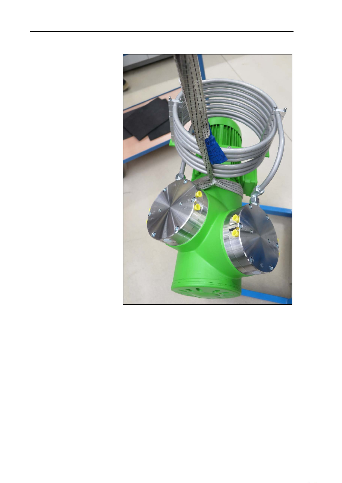
Transportation with harness
Fig. 4: Position of the harness (exemplary)
1. Pull the harness through among the pump (see Fig. 4).
16 Translation of original Operating and Installation Instructions, english, KNF 308 934-308937 09/18

Diaphragm pump N 2400.15 Transportation
Fig. 5:
2. Fix the harness between compressor housing and motor (Fig.
5).
3. Make sure that the lifting load cannot be transferred from the
belt to the pump connection.
4. Use a lifting device to lift the pump out of the packaging.
5. Place the pump carefully at the installati on loc at ion .
Translation of original Operating and Installation Instructions, english, KNF 308 934-308937 09/18 17

Installation and connection Diaphragm pump N 2400.15
Mounting dimensions
7. Installation and connection
Only install and operate the pumps under the pneumatic operating
parameters and conditions described in Chapter 4, Technical Data.
Observe the safety precautions (see Chapter 3).
7.1. Installation of the pump
Before installation, store the pump at the installation location to
bring it up to ambient temperature.
See Fig. 6 (pump series N 2400.15 SPE) and Fig. 7 (pump
series N 2400.15 STE) for mounting dimensions.
Fig. 6: Mounting dimensions pump series N 2400.15 SPE (All dimensional
tolerances conform to DIN ISO 2768-1, Tolerance Class V)
18 Translation of original Operating and Installation Instructions, english, KNF 308 934-308937 09/18

Diaphragm pump N 2400.15 Installation and connection
Danger of burns from hot surfaces
Hot
pump.
Install the pump so that the motor fan can intake
Cooling air supply
Immediate ambient of the hot
Installation location
pump parts
Fig. 7: Mounting dimensions pump series N 2400.15 STE (All dimensional
tolerances conform to DIN ISO 2768-1, Tolerance Class V)
surfaces may be caused by overheating of the
WARNING
sufficient cooling air.
When installing, make sure that there are no combustible or
thermally malleable objects placed in the immediate ambient of
the hot pump parts (head, motor).
Make sure that the installation location is dry and the pump is
protected against rain, splash, hose and drip water as well as
other pollutions.
Make sure, that the installation location is accessible for
maintenance and service.
Ensure that the pump is securely attached to the mounting
holes provided. If necessary, fasten the pump to the base plate
with rubber-bonded metals (see accessories, chapter 11; information on pump weight, chapter 4 Tec hnic al Dat a).
Translation of original Operating and Installation Instructions, english, KNF 308 934-308937 09/18 19
Ensure that there is no access to moving parts (such as from
the bottom of the pump housing).

Installation and connection Diaphragm pump N 2400.15
The IP protection class of the pump motor is indicated on the
type plate.
Personal injury and/or damage to property because
of vibration
In conjunction with adjacent components, vibration of
the pump may result in crushing and/or damage to
these components.
Extreme danger from electrical shock
Only have the pump connected by an authorized
For max. operating current of the pump see pump’s type plate.
Installation position
Foreign matter protection
Install the pump at the highest point in the system to prevent
condensate from collecting in the pump head.
Protect the pump from dust.
Protect the pump from vibrations and jolts.
WARNING
The pump can be installed in any position. Secure the pump
with metallic screws to the attachment points shown.
Protect the pump against contact and intrusion of foreign mat-
ter.
Make sure that vibrations of the pump do not
result in hazards associated with adjacent components.
7.2. Electrical connection
specialist.
DANGER
When connecting the device to a power source, the relevant
standards, directives, regulations, and technical standards
must be observed.
For electrical connection, carefully read and observe the motor
operating instructions (also including information on insulation
resistance measurement).
In the electrical installation, arrangements (complying with
EN 60335-1) must be made for disconnecting the pump motor
from the electrical supply.
The motors of the pump must be protected according to
EN 60204-1 (protection against excess current, or overloading).
Only have the pump connected when the power
supply is disconnected.
20 Translation of original Operating and Installation Instructions, english, KNF 308 934-308937 09/18
It is recommended that an additional “Emergency Stop” switch
is installed.
The pump must be installed so that contact with live parts is
impossible.

Diaphragm pump N 2400.15 Installation and connection
The pumps are fitted as standard with PTC sensors to protect
against overloading (connection according to operating instructions of the motor).
The 3~ motors are provided for the operation with frequency
converter.
See operating instructions of the motor for permissible deviation of the voltage.
Set the direction of rotation in accordanc e with the arr o w on
the fan guard (see
instructions).
Personal injury or damages to property by ejected
protective
If the
pump hasn’t been removed, it could be ejected because of the overpressure during operation.
Attach connection cables
PTC sensors
Connected
Pressure relief device
Pump exhaust
Fasten the connection cables so that:
the cables do not contact moving or hot parts.
the cables will not chafe or be damaged on sharp edges or
corners.
no pulling or pushing forces are exerted on the cable’s
connection points (strain relief).
Connecting pump
1. Compare the supply data with the data on the motor plate. For
maximum operating current of the pump see pump’s type
plate.
2. Open terminal box cover.
3. Connect the earth (ground) wire to the motor.
4. Connect the mains cables according to the operating instruction of the motor.
5. Close the terminal cover box.
7.1 Pump installation and motor operating
7.3. Pneumatic connectio n
CAUTION
Only connect components to the pump which are designed for
components
Translation of original Operating and Installation Instructions, english, KNF 308 934-308937 09/18 21
the pneumatic data of the pump (see Chapter 4, Technical Data).
Protect the pump with a pressure relief device between the
pressure connection of the pump and the first shut-off valve.
If the pump s used as a vacuum pump, safely discharge the
pump exhaust at the pump’s pneumatic outlet.
plugs
protective plug at the pressure side of the
Remove the protective plug during the installa-
tion.

Installation and connection Diaphragm pump N 2400.15
A marking on the pump head shows the direction of flow.
Risk of injury due to mixing up suction and pressure
side
Mixing up the suction and pressure side can lead to
the rupture
and pressure side.
Pneumatic noises can be reduced or dissipated by using a
silencer (see Chapter
Disengaging
KNF recommends mechanically disengaging the pump from
the piping system. This can be achieved with flexible tubing or
pipes, for example. This will avoid transferring to the system
any pump oscillations that may arise.
Connecting pump
CAUTION
Observe the marking of the inlet/outlet.
1. Remove the protective plugs from the hose connection
threads.
of connected components on the suction
2. Connect the suction line and pressure line (see Chapter 4,
Tab. 10 for mounting dimensions).
3. Lay the suction and pressure line at a downward angle to prevent condensate from running into the pump.
11.2 Accessory).
22 Translation of original Operating and Installation Instructions, english, KNF 308 934-308937 09/18

Diaphragm pump N 2400.15 Installation and connection
Water cooling (see 11.2 Accessory) can increase the service
l
bient temperatures.
Parameter
Value
Water temperature
+ 5°C to + 30°C
Water flow quantity [l/min]
1.0
The base plate is shown as an additional accessory in the following dimension drawings.
Mounting dimensions
7.4. Connecting the water cooling system
(optional)
ife of the diaphragm, especially at high pressures or high am-
Recommended parameters
Tab. 12
Mounting dimensions see Fig. 8 and Fig. 9.
Fig. 8: Mounting dimensions pump series N 2400.15 SPE (All dimensional
tolerances conform to DIN ISO 2768-1, Tolerance Class V)
Translation of original Operating and Installation Instructions, english, KNF 308 934-308937 09/18 23

Installation and connection Diaphragm pump N 2400.15
Fig. 9: Mounting dimensions pump series N 2400.15 STE (All dimensional
tolerances conform to DIN ISO 2768-1, Tolerance Class V)
Operate the water connection up to max. 1.0 bar.
Drain water runoff safely.
The flow direction is permissible in both directions.
24 Translation of original Operating and Installation Instructions, english, KNF 308 934-308937 09/18
Diaphragm pump N 2400.15 Operation
Danger of burns from hot pump parts or hot medium
During or after operation of the pump, some pump
parts may be hot.
Injury of the eyes
During excessive approach to the inlet or outlet of
the pump, the eyes could be injured by the upcoming
vacuum or overpressure.
Hazard of the pump head bursting due to excessive
pressure increase
Only throttle or regulate the air or gas quantity in
8. Operation
WARNING
WARNING
Only operate the pumps under the operating parameters and
conditions described in Chapter 4. Technical Data.
Make sure the pumps are used properly (see Chapter 2.1).
Make sure the pumps are not used improperly (see Chapter
2.2).
Observe the safety precautions (see Chapter 3).
The pumps are intended for installation. Before putting them
into service it must be established that machinery or equipment
in which they are installed meets the relevant regulations.
Allow the pump to cool after operation.
Take safety precautions against the contact of
hot parts/media.
Don’t look into the pump’s inlet or outlet during
the operation.
Translation of original Operating and Installation Instructions, english, KNF 308 934-308937 09/18 25
WARNING
Do not exceed max. permissible operating pres-
sure (see Chapter
Monitor pressure during operation.
If the pressure exceeds the maximum permissi-
ble operating pressure, immediately switch off
pump and eliminate fault (see Chapter
bleshooting).
the suction line to prevent the maximum permis-
sible operating pressure from being exceeded.
If the air or gas quantity in the pressure line is
throttled or regulated, make sure that the maxi-
mum permissible operating pressure is not ex-
ceeded.
Ensure that the pump outlet is not closed or
constricted.
4. Technical Data).
10. Trou-

Operation Diaphragm pump N 2400.15
Excessive pressure (with all of the related hazards) can be
prevented by placing a bypass line with a pressure
between the pressure and suctions sides of the pump. For
further information, contact our technical adviser (contact data:
see www.knf.com) .
Automatic starting can cause personal injur y and
pump damage
When the operation of the pump is interrupted by the
trigging device for PTC sensors, the pump will restart
automatically after coolin g do wn.
Operation with an open suction-side gas connection can lead
to the suction of contaminants and objects.
The pump may not start up against pressure or vacuum during
switch-on. This also applies in operating following a brief power
failure. If a pump starts against pressure or vacuum, it may
block. This activates the
the pump switches off.
Pump standstill
Vapors as media
Switching off the pump /
Recommissioning
WARNING
With the pump at a standstill, open pressure and suction lines
to normal atmospheric pressure.
Take all necessary care to prevent this leading
to a dangerous situation.
-relief valve
removing from operation
trigging device for PTC sensors, and
Make sure that normal atmospheric pressure is present in the
lines during switch-on.
The life of the diaphragm is prolonged the formation of condensate
is avoided. Therefore the following precautions should be taken:
Run the pump for a few minutes to warm it up before handling
saturated or nearly saturated vapors.
KNF recommends: When transferring aggressive media, flush
the pump prior to switch off (see Chapter 9.2.1) to increase the
service life of the diaphragm.
Restore the system to normal atmospheric pressure (release
pneumatic pressure in pump).
Before recommissioning, the relevant norms, directives, regu-
lations and technical standards must be observed at the power
source.
26 Translation of original Operating and Installation Instructions, english, KNF 308 934-308937 09/18

Diaphragm pump N 2400.15 Servicing
Component
Servicing interval
Pump - Regular inspection for external dam-
es in noise and vibration
Tube connection
Regular inspection for external damage or leaks
Diaphragm and reed
- Change if pressure or flow rate of
output decreases
Danger of burns from hot pump parts
The pump head or motor may be hot even after the
pump has been shut off.
Health hazard due to dangerous substances
in the pump
Depending on the substances transferred, caustic
burns or poisoning are possible.
Ensure that no liquids enter the inside of the housing during
cleaning work.
9. Servicing
9.1. Servicing schedule
age or leaks
- Regular check for noticeable chang-
-
valves
the pump changes for no apparent
reason
- Replace if bent or worn
- Replace at the latest, when pump
Tab. 13
9.2. Cleaning
9.2.1. Flushing pump
KNF recommends: When transferring aggressive media, flush
the pump under atmospheric conditions some minutes with air
(or, if necessary for safety reasons, with an inert gas) prior to
switch-off to increase the service life of the diaphragm.
Drain the media safely.
9.2.2. Cleaning pump
CAUTION
Allow the pump to cool after operation.
CAUTION
Only use solvents for cleaning if the head materials cannot be
If compressed air is available, blow out the components.
Translation of original Operating and Installation Instructions, english, KNF 308 934-308937 09/18 27
Wear protective clothing if necessary, e.g. pro-
tective gloves.
Clean pump with suitable measures.
attacked (check the resistance of the materials).

Servicing Diaphragm pump N 2400.15
Health hazard due to dangerous substances
in the pump!
Depending on the substance
burns or poisoning are possible.
Danger of burns from hot pump parts
The pump head or motor may be hot even after the
pump
Spare part*
Position**
Quantity
Diaphragm
(10)
1 (per pump head)
Reed valve
(5)
2 (per pump head)
Valve stopper
(3)
2 (per pump head)
O-Ring
(7)
2 (per pump head)
O-Ring (only .13)
(11)
1 (per pump head)
O-Ring (only .13)
(12)
1 (per pump head)
Quantity
Tools/material
1
Allen key 4 with torque indicator
1
Allen key 6 with torque indicator
1
Philips screwdriver No. 2
1
Adjustable pin-wrench for two-hole nuts, pin dia.
1
Felt-tip pen
1
Hot air blower
1
Adhesive (Delo ML5249) or comparable product
Conditions
Information on procedure
Spare parts
Tools and material
9.3. Replacing diaphragm and reed valves
Motor disconnected from mains and de-energized.
Pump and motor cooled.
Pump free of dangerous substances.
Tubes/pipes removed from pump’s pneumatic inlet and outlet.
With multi-head pumps, parts of the individual pump heads can be
confused.
Replace diaphragm and reed valves of the individual pump
heads consecutively.
WARNING
Wear protective clothing of necessary, e.g. pro-
tective gloves.
Clean pump with suitable measures.
CAUTION
Tab. 14 *According to spare parts list, Chapter 11
**According to Fig. 10
has been shut off.
Allow the pump to cool after operation.
transferred, caustic
28 Translation of original Operating and Installation Instructions, english, KNF 308 934-308937 09/18
Tab. 15 *According to accessories list, Chapt er 11
4mm, length of wrench ca. 160 mm (available as
‘wrench for retainer plate’, a KNF accessory, see
Chapter
11.

Diaphragm pump N 2400.15 Servicing
The following item numbers refer to Fig. 10, unless otherwise
indicated.
This helps avoid incorrect assembly later.
1 Hexagon socket head cap
screw
2 Slotted cheese head screw
3 Limiter
4 Head plate
5 Reed valve
6 Hexagon socket head cap
screw
7 O-ring
8 Diaphragm
9 Diaphragm support
10 Retainer plate
11 O-ring (only .13)
12 O-ring (only .13)
13 Housing
14 Intermediate plate
15 Diaphragm spacer(s)
Fig. 10: Pump parts
Removing pump head
1. Take the steps necessary to gain access to the motor cooling
fan:
Undo the screws that hold the fan cover (Fig. 2/7) and rem ove
the fan cover.
2. Remove the pneumatic connection or the interstage cooler
between the pump heads: To do so, mark the union nuts (Fig.
2/7) according to Fig. 11 and loosen them.
3. Mark the position of head plate (4), intermediate plate (14) and
Fig. 11: Marking of the union nuts
housing (13) relative to each other by a drawing line with a felttip pen.
4. Undo the six hexagon socket head cap screws (1) and the two
screws (6); lift off head plate (4) and intermediate plate (14).
Translation of original Operating and Installation Instructions, english, KNF 308 934-308937 09/18 29

Servicing Diaphragm pump N 2400.15
Danger of burns from hot parts
Touching a hot retainer plate or any other hot pump
part can burn your skin.
Always use a face wrench to remove the retainer
There might be adhesive residue on the external thread of the
retainer plate and on the internal thread of the diaphragm support (9
Make sure the diaphragm spacer(s) (15) do not fall into the
pump housing.
With removal of the diaphragm support (
the diaphragm spacer(s) (
With reassembly insert the exact number of diaphragm spacer(s) (
5. Carry out steps 3 and 4 for the second pump head.
Changing diaphragm
1. Use a hot-air blower (T= approx. 400°C) to heat the retainer
plate (10) for about five minutes until it heats up to approx.
100°C.
2. You must observe the following when removing the retainer
plate:
WARNING
Use the wrench for retainer plate to turn it anti-clockwise and
remove the retainer plate (10) from the diaphragm support (9).
3. Remove diaphragm (8).
4. Only .13:
Remove the O-ring (12) from the housing (13).
5. Only .13:
Remove the O-ring (11) from the diaphragm support (9).
6. Inspect all parts for dirt and clean them if necessary.
Wear protective gloves.
plate.
Always place the retainer plate on a heatproof
surface.
). Remove any adhesive residue!
15).
9) remove and retain
7. Turn the fan until the diaphragm support (9) is mid-stroke.
8. Place the new diaphragm (8) on the diaphragm support (9);
9. Only .13:
30 Translation of original Operating and Installation Instructions, english, KNF 308 934-308937 09/18
10. O nly .13:
15).
For N 2400.15 SPE:
Take care that the beads on the outer and inner edges of the
diaphragm are properly seated in the grooves in housing and
diaphragm support respectively.
Fit the new O-ring (12) in the housing (13).
Fit the new O-ring (11) in the diaphragm support (9).

Diaphragm pump N 2400.15 Servicing
Before you screw in the retainer plate completely, unscrew it
360 degrees to ensure that the thread flanks of the retainer
plate and the diaphragm support, respectively,
adhesive.
Be sure to observe the adhesive’s USE BY date!
Adhesive might not be as effective if used after its USE BY
date.
Be sure to allow the adhesive to cure before restarting the
pump.
Adhesive curing lasts approx. 24 hours!
Take care that the reed valves are symmetrically to the valve
bore.
In order to ensure the required gas tightness of the pump head
after maintenance, a leak test must be carried out.
11. Completely cover the thread start of the retainer plate (10) and
the threaded hole of the diaphragm support (9) with adhesive.
Then screw the retainer plate into the diaphragm support.
are coated with
12. Tighten the retainer plate (10) firmly; use the wrench for retain-
13. Carry out steps 1 to 12 for the second pump head.
Changing reed valves
1. Remove the two O-rings (7) from the intermediate plate (14).
2. Undo the two screws (2) and remove valve limiters (3) and
3. Fit new reed valves and valves limiters on pressure and suc-
4. Carry out steps 1 to 3 for the second pump head.
Mounting pump head
er plate to do so (tightening torque: 20 Nm).
reed valves (5) from the intermediate plate (14).
tion sides.
1. Place intermediate plate (14) on housing (13) according to the
mark made previously (at the same time, keep the diaphragm
in its mid-position by holding the motor fan).
2. Fit the two new O-rings (7) in the intermediate plate (14).
3. Place head plate (4) on intermediate plate (14) according to
the mark made previously.
4. Screw the hexagon socket head cap screws (1) and (6) in one
or two turns.
5. Tighten the two hexagon socket head cap screws (6) (tight ening torque: 6 Nm); then tighten the six hexagon socket head
cap screws (1) diagonally (tightening torque: 9 Nm).
Translation of original Operating and Installation Instructions, english, KNF 308 934-308937 09/18 31

Servicing Diaphragm pump N 2400.15
6. Turn the fan to check that the pump rotates freely.
7. Carry out steps 1 to 6 for the second pump head:
8. Remount fan cover (Fig. 2/7).
9. Remount the pneumatic connection or the interstage cooler.
To do so, tighten the union nut in the original position (as it
was marked during disassembly, see Fig. 11).
32 Translation of original Operating and Installation Instructions, english, KNF 308 934-308937 09/18

Diaphragm pump N 2400.15 Troubleshooting
Extreme danger from electrical shock!
Pump does not transfer
Cause
Fault remedy
Pump is not connected with the
Connect pump with the power source.
No voltage in the power source.
Check room fuse and switch on if necessary.
Triggering device for PTC sen-
Disconnect pump from mains.
Connections or lines blocked.
Check connections and lines.
Remove blockage.
External valve is closed or filter
Check external valves and filters.
Condensate has collected in
Detach the condensate source from the pump.
with air (if necessary for safety reasons: with an inert gas).
Diaphragm or reed valves are
Replace diaphragm and reed valves (see Chapter 0).
Flow rate, pressure or vacuum too low
Cause
Fault remedy
Condensate has collected in
Flush the pump (see Chapter 9.2.1).
There is gauge pressure on
Change the pressure conditions.
Pneumatic lines or connection
Disconnect pump from system to determine output values.
necessary.
Leaks occur on connections,
Eliminate leaks.
Connections or lines completely
Check connections and lines.
Head parts are soiled.
Clean head components.
Diaphragm or reed valves are
Replace diaphragm and reed valves (see Chapter 0).
10. Troubleshooting
Disconnect the pump power supply before work-
ing on the pump.
DANGER
Check the pump (see Tab. 16 and Tab. 17).
power source.
Make sure the pump is de-energized and se-
cure.
sors of the motor has operated
following to over-heating.
is clogged.
pump head.
worn.
The pump does not achieve the output specified in the Technical data or the data sheet.
pump head.
pressure side an at the same
time vacuum or a pressure
above atmospheric pressure on
suction side.
Allow pump to cool.
Trace cause of over-heating and eliminate it.
Flush the pump under atmospheric conditions some minutes
Tab. 16
Install pump at highest point in system.
parts have an insufficient cross
section.
lines or pump head.
or partially jammed.
worn.
Eliminate throttling (e.g. valve) if necessary.
Use lines or connection parts with larger cross section if
Remove the jamming parts and particles.
Tab. 17
Translation of original Operating and Installation Instructions, english, KNF 308 934-308937 09/18 33

Troubleshooting Diaphragm pump N 2400.15
Fault cannot be rectified
If you are unable to determine any of the specified causes, send
the pump to KNF Customer Service (contact data: see
www.knf.com).
1. Flush the pump under atmospheric conditions some minutes
with air (if necessary for safety reasons: with an inert gas) to
free the pump head of dangerous or aggressive gases (see
Chapter 9.2.1).
2. Clean the pump (see Chapter 9.2.2).
3. Send the pump, together with completed Health and Safety
Clearance and Decontamination Form (Chapter 13), to KNF
stating the nature of the transferred medium.
34 Translation of original Operating and Installation Instructions, english, KNF 308 934-308937 09/18

Diaphragm pump N 2400.15 Spare parts and accessories
Spare part
Position*
Order No.
Diaphragm
(10)
027252
Reed valve
(5)
003475
Valve stopper
(3)
001714
O-ring
(7)
047016
O-ring (only .13)
(11)
047372
O-ring (only .13)
(12)
047373
Spare part
Position*
Order No.
Diaphragm
(10)
118095
Reed valve
(5)
003475
Valve stopper
(3)
001714
O-ring
(7)
002458
O-ring (only .13)
(11)
002461
O-ring (only .13)
(12)
045499
Accessory
Order No.
Wrench for retainer plate
018816
Adhesive (Delo ML5249)
020088
Connection water cooling device
305444
Base plate with rubber-bonded metals:
304476
Inlet filter G 1/2
316662
11. Spare parts and accessories
11.1. Spare parts
N 2400.15 SPE
Tab. 18 *according to Fig. 10
N 2400.15 STE
Tab. 19 *according to Fig. 10
11.2. Accessory
N 2400.15 SPE
N 2400.15 STE
N 2400.15 SPE
N 2400.15 STE
Tab. 20
Translation of original Operating and Installation Instructions, english, KNF 308 934-308937 09/18 35

Returns Diaphragm pump N 2400.15
12. Returns
Pumps and systems used in laboratories and process-based
industries are exposed to a wide variety of conditions. This means
that the components contacting pumped media could become
contaminated by toxic, radioactive, or otherwise hazardous substances.
For this reason, customers who send any pumps or systems back
to KNF must submit a Health and safety clearance and decontamination form in order to avoid a hazardous situation for KNF employees. This Health and safety clearance and decontamination
form provides the following information, among other things:
physiological safety
whether medium-contacting parts have been cleaned
whether the equipment has been decontaminated
media that have been pumped or used
To ensure worker safety, work may not be started on pumps or
systems without a signed Health and safety clearance and decontamination form.
For optimal processing of a return, a copy of this declaration
should be sent in advance via e-mail, regular mail, or fax to KNF
Customer Service (co ntac t data: see www.knf.com). In order to
avoid endangering employees who open the shipment’s packaging, despite any residual hazards, the original version of the Health
and safety clearance and decontamination form must accompany
the delivery receipt on the outside of the packaging.
The template for Health and safety clearance and decontamination
form is included with these Operating Instructions and may also be
downloaded from the KNF website.
The customer must specify the device type(s) and serial number(s)
in the Health and safety clearance and decontamination form in
order to provide for the unambiguous assignment of the Declaration to the device that is sent to KNF.
In addition to the customer’s declaration of physiological safety,
information about operating conditions and der customer’s application are also of importance to ensure that the return shipment is
handled appropriately. Therefore, the Health and safety clearance
and decontamination form requests this information as well.
36 Translation of original Operating and Installation Instructions, english, KNF 308 934-308937 09/18

Diaphragm pump N 2400.15 Health and safety clearance and decontamination form
13. Health and safety clearance and decontamination form
Translation of original Operating and Installation Instructions, english, KNF 308 934-308937 09/18 37


KNF worldwide
Find your
local KNF partner on www.knf.com
 Loading...