

KNF N 143 SN.12 E, N 143 SV.12 E, N 143 AN.12 E, N 186.1.2 AN.12 E, N 186.1.2 AV.12 E Operating And Installation Instruction
...
Diaphragm-Gas Sampling Pumps
with double diaphragm System
N 143 AN.12 E
N 143 AV.12 E
N 143 SN.12 E
N 143 SV.12 E
Operating and
Installation
Instructions
Read and observe these Operating and Installation Instructions!
N 186.1.2 AN.12 E
N 186.1.2 AV.12 E
N 186.3 AN.12 E
N 186.3 AV.12 E
N 186.1.2 SN.12 E
N 186.1.2 SV.12 E
N 186.3 SN.12 E
N 186.3 SV.12 E
KNF Neuberger GmbH
Alter Weg 3
D-79112 Freiburg
Germany
Phone +49-(0)7664-5909-0
Fax +49-(0)7664-5909-99
E-mail: info@knf.de
www.knf.de
KNF 121610-121613 07/16
Translation of original Operating and Installation Instructions, english Keep for future use!
Contents Page
1. About this document ................................................................. 2
2. Use ........................................................................................... 3
3. Safety ....................................................................................... 5
4. Technical Data.......................................................................... 7
5. Design and function ................................................................ 11
6. Installation and connection ..................................................... 14
7. Operation ................................................................................ 18
8. Servicing ................................................................................. 20
9. Troubleshooting ...................................................................... 25
10. Spare parts and accessories .................................................. 27
11. Returns ................................................................................... 28
12. Health and safety clearance and decontamination form ........ 29

About this document Diaphragm Pumps N 143/186.12
WARNING
A danger warning is located here.
Possible consequences of a failure to observe the
warning are specified here. The signal word, e.g.
Warning, indicates the danger level.
Measures for avoiding the danger and its conse-
quences are specified here.
Signal word
Meaning
Consequences if not observed
DANGER
warns of immediate danger
Death or serious injuries
and/or serious damage are the
consequence.
WARNING
warns of possible
danger
Death or serious injuries
and/or serious damage are
possible.
CAUTION
warns of a possibly
dangerous situation
Minor injuries or damage are
possible.
This symbol refers to important information.
Project pumps
1. About this document
1.1. Using the Operating and Installation Instructions
The Operating and Installation Instructions are part of the pump.
Pass on the Operating and Installation Instructions to the next
owner.
Customer-specific project pumps (pump models which begin with
"PJ" or "PM") may differ from the Operating and Installation Instructions.
For project pumps, also observe the agreed upon specifica-
tions.
1.2. Symbols and markings
Warning
Danger levels
Tab. 1
Other information and symbols
An activity to be carried out (a step) is specified here.
1. The first step of an activity to be carried out is specified here.
Additional, consecutively numbered steps follow.
2 Translation of original Operating and Installation Instructions, english, KNF 121610-121613 07/16

Diaphragm Pumps N 143/186.12 Use
Operating parameters and
conditions
Requirements for
transferred medium
2. Use
2.1. Proper use
The pumps are exclusively intended for transferring gases and
vapors.
Owner's responsibility
Only install and operate the pumps under the operating parameters
and conditions described in chapter 4, Technical data.
Protect the compressors with a pressure relief device between the
pressure side of the compressor and the first shut-off valve.
Only complete pumps may be taken into service.
Make sure that the installation location is dry and the pump is
protected against rain, splash, hose and drip water.
The gas-tightness of the connections between the application
pipes and the pump (or the pump connection) must be checked
regularly; with leaky connections, there is a danger that hazardous
gases or vapors may escape from the pump system.
Before using a medium, check whether the medium can be transferred danger-free in the specific application case.
Before using a medium, check the compatibility of the materials of
the pump head, diaphragm and valves with the medium.
Danger of dangerous gas mixtures during operation of the pump if
the working diaphragm ruptures: Depending on the medium being
pumped, a rupture of the working diaphragm may produce a potentially dangerous mixture when the medium mixes with the air in the
innerspace between the working diaphragm and the safety diaphragm.
Evacuate the innerspace between the working diaphragm
and the safety diaphragm (see position 5 in Fig. 4, p. 12)
through the two holes in the pump head. At two-headed
pumps this is applicable for both pump heads.
KNF recommends monitoring the pressure of the evacuat-
ed innerspace between the working diaphragm and the
safety diaphragm. Immediately stop the pump if the pressure becomes elevated.
Immediately stop the pump if the working diaphragm rup-
tures. The working diaphragm and the safety diaphragm
must be replaced before continuing with operation (see
chapter 8, Maintenance).
Translation of original Operating and Installation Instructions, english, KNF 121610-121613 07/16 3
If pressure or flow rate change without apparent reason,
immediately switch off the pump and check for damages.
Only transfer gases which remain stable under the pressures and
temperatures occurring in the pump.

Use Diaphragm Pumps N 143/186.12
2.2. Improper use
The pumps may not be operated in an explosive atmosphere.
The pumps are not suitable for transferring liquids.
The pumps are not suitable for transferring dusts.
Pumps designed to create either a vacuum or an overpressure
must not be used for these two purposes simultaneously.
An overpressure must not be applied to the suction side of the
pump.
Pumps with three-phase motor are not provided for the operation
with frequency converter.
4 Translation of original Operating and Installation Instructions, english, KNF 121610-121613 07/16

Diaphragm Pumps N 143/186.12 Safety
Note the safety precautions in chapters 6. Installation and
connection, and 7. Operation.
Personnel
Working in a safety-
conscious manner
Handling dangerous media
Handling combustible media
Environmental protection
EC Directives / Standards
3. Safety
The pumps are built according to the generally recognized rules of
technology and in accordance with the occupational safety and
accident prevention regulations. Nevertheless, dangers can result
during their use which lead to injuries to the user or others, or to
damage to the pump or other property.
Only use the pumps when they are in a good technical and proper
working order, in accordance with their intended use, observing the
safety advice within the operating and installation instructions, at all
times.
Make sure that only trained and instructed personnel or specially
trained personnel work on the pumps. This especially applies to
assembly, connection and servicing work.
Make sure that the personnel has read and understood the operating and installation instructions, and in particular the "Safety"
chapter.
Observe the accident prevention and safety regulations when
performing any work on the pump and during operation.
The pump heads heat up during operation – avoid contact with them.
When transferring dangerous media, observe the safety regula-
tions when handling these media.
Be aware that the pumps are not designed to be explosion-proof.
Make sure the temperature of the medium is always sufficiently
below the ignition temperature of the medium, to avoid ignition or
explosion. This also applies for unusual operational situations.
Note that the temperature of the medium increases when the pump
compresses the medium (compressor operation).
Hence, make sure the temperature of the medium is sufficiently
below the ignition temperature of the medium, even when it is
compressed to the maximum permissible operating pressure of the
pump. The maximum permissible operating pressure of the pump
is stated in the technical specifications (chapter 4).
If necessary, consider any external sources of energy, such as
radiation, that may add heat to the medium.
In case of doubt, consult the KNF customer service.
Store all replacement parts in a protected manner and dispose of
them properly in accordance with the applicable environmental
protection regulations. Observe the respective national and international regulations. This especially applies to parts contaminated
with toxic substances.
For the purposes of the Machinery Directive 2006/42/EC, pumps
are “partly completed machinery,” and are therefore to be regarded
as not ready for use. Partly completed machinery may not be
Translation of original Operating and Installation Instructions, english, KNF 121610-121613 07/16 5

Safety Diaphragm Pumps N 143/186.12
Customer service and
repairs
commissioned until such time as it has been determined that the
machine in which the partly completed machinery is to be
assembled is in conformity with the provisions of the Machinery
Directive 2006/42/EC. The following essential requirements of
Annex I of Directive 2006/42/EC (general principles) are applied
and observed:
General Principles No. 1
No. 1.1.2. / 1.1.3. / 1.3.1. / 1.3.3. / 1.3.4. / 1.4.1. / 1.5.1. /
1.5.2. / 1.5.8. / 1.5.9. / 1.7.4. / 1.7.4.1. / 1.7.4.3.
As these partly completed machinery are OEM-models the power
supplies and the equipment for disconnecting and switching-off the
partly completed machinery respectively have to be considered
when mounting as well as over-current and overload protective
gear.
In addition a protection against mechanical parts in motion and hot
parts, if existing, has to be provided when mounting.
The pumps conform to the Directive 2011/65/EU (RoHS2).
The following harmonized standards have been used:
DIN EN 50581
DIN EN 55014-1/2
DIN EN 61000-3-2/3
DIN EN 60204-1
Only have repairs to the pumps carried out by the KNF Customer
Service responsible.
Use only genuine parts from KNF for servicing work.
6 Translation of original Operating and Installation Instructions, english, KNF 121610-121613 07/16

Diaphragm Pumps N 143/186.12 Technical Data
Assembly
Material
Head plate, intermediate plate,
intermediate ring
Aluminium
Working diaphragm
CR
Safety diaphragm
NBR
Valve plate
CR
Retainer plate
Stainless Steel
Conrod disc
Aluminium
O-rings
NBR
Assembly
Material
Head plate, intermediate plate,
Intermediate ring
Aluminium
Working diaphragm
FPM
Safety diaphragm
FPM
Valve plate
FPM
Retainer plate
Stainless Steel
Conrod disc
Aluminium
O-rings
FPM
Assembly
Material
Head plate, intermediate plate,
Stainless Steel
Intermediate ring
Aluminium
Working diaphragm
CR
Safety diaphragm
NBR
Valve plate
CR
Retainer plate
Stainless Steel
Conrod disc
Aluminium
O-rings
NBR
4. Technical Data
Pump materials
N 143 AN.12 E
N 186.1.2 AN.12 E
N 186.3 AN.12 E
Tab. 2
N 143 AV.12 E
N 186.1.2 AV.12 E
N 186.3 AV.12 E
Tab. 3
N 143 SN.12 E
N 186.1.2 SN.12 E
N 186.3 SN.12 E
Translation of original Operating and Installation Instructions, english, KNF 121610-121613 07/16 7
Tab. 4

Technical Data Diaphragm Pumps N 143/186.12
Assembly
Material
Head plate, intermediate plate,
Stainless Steel
Intermediate ring
Aluminium
Working diaphragm
FPM
Safety diaphragm
FPM
Valve plate
FPM
Retainer plate
Stainless Steel
Conrod disc
Aluminium
O-rings
FPM
Parameter
Value
Max. permissible operating pressure [bar g]
3.0
Ultimate vacuum [mbar abs.]
100
Delivery rate at atm. pressure [l/min]*
30
Parameter
Value
Max. permissible operating pressure [bar g]
3.0
Ultimate vacuum [mbar abs.]
100
Delivery rate at atm. pressure [l/min]*
50
Parameter
Value
Max. permissible operating pressure [bar g]
-
Ultimate vacuum [mbar abs.]
3
Delivery rate at atm. pressure [l/min]*
30
N 143 SV.12 E
N 186.1.2 SV.12 E
N 186.3 SV.12 E
Tab. 5
Pneumatic values
N 143 AN.12 E N 143 SN.12 E
N 143 AV.12 E N 143 SV.12 E
Tab. 6 *Liters in standard state (1,013 mbar)
N 186.1.2 AN.12 E N 186.1.2 SN.12 E
N 186.1.2 AV.12 E N 186.1.2 SV.12 E
Tab. 7 *Liters in standard state (1,013 mbar)
N 186.3 AN.12 E N 186.3 SN.12 E
N 186.3 AV.12 E N 186.3 SV.12 E
8 Translation of original Operating and Installation Instructions, english, KNF 121610-121613 07/16
Tab. 8 *Liters in standard state (1,013 mbar)

Diaphragm Pumps N 143/186.12 Technical Data
Parameter
Value
N 143 _ _.12 E and
N 186.3 _ _.12 E
Thread size G 1/4
N 186.1.2 _ _.12 E
Taper bush type pipe union for
pipe OD 10
Hole for pressure monitoring of
intermediate space between
working diaphragm and safety
diaphragm
Thread size G 1/8
Parameter
Value
Electrical data
See type plate
Protection class motor
IP44
Maximum permitted mains
voltage fluctuations
+/- 10 %
The pumps with capacitor motor are fitted as standard with a
thermal-switch to protect against overloading.
Pump type
Weight (kg)
N 143 AN.12 E
N 143 AV.12 E
approx. 13.0
N 143 SN.12 E
N 143 SV.12 E
approx. 15.5
N 186.1.2 AN.12 E
N 186.1.2 AV.12 E
approx. 18.5
N 186.1.2 SN.12 E
N 186.1.2 SV.12 E
approx. 23.0
N 186.3 AN.12 E
N 186.3 AV.12 E
approx. 18.0
N 186.3 SN.12 E
N 186.3 SV.12 E
approx. 23.5
Thermal-switch
Pneumatic Connections
Tab. 9
Electrical data
Tab. 10
Weight
Tab. 11
Translation of original Operating and Installation Instructions, english, KNF 121610-121613 07/16 9

Technical Data Diaphragm Pumps N 143/186.12
Ambient and media temperature
Permissible ambient temperature
+ 5 °C to + 40 °C
Permissible media temperature
+ 5 °C to + 40 °C
Gas-tightness
Gas-tightness* of pump
head/pump heads (leak rate)
< 6 x 10⁻⁶ mbar l/s**
Other
Dimensions N 143 _ _.12 E:
L x H x W [mm]
400 x 223 x 177
Dimensions N 186.1.2 _ _.12 E:
L x H x W [mm]
502 x 225 x 288
Dimensions N 186.3 _ _.12 E:
L x H x W [mm]
450 x 225 x 288
Maximum permissible ambient
relative humidity
80 % for temperatures up to
31 °C, decreasing linearly to
50 % at 40 °C
Max. altitude of site
[m above sea level]
2000
Other parameters
Tab. 12
* Perform a leak test in order to ensure gas-tightness after opening
the pump head/pump heads or after exchanging diaphragms and
valve plates.
** Values valid for helium leak test.
Additional equipment
The pump is equipped with a safety diaphragm.
Refer to chapter 5 for an explanation of purpose and prin-
ciple.
Refer to chapter 6.4 for notes on assembly and connec-
tion.
Refer to chapter 7 for notes on operation.
10 Translation of original Operating and Installation Instructions, english, KNF 121610-121613 07/16

Diaphragm Pumps N 143/186.12 Design and function
1 Pneumatic outlet (G ¼)
2 Pneumatic inlet (G ¼)
3 Terminal box (electrical
connection)
4 Motor
5,6 Screw plug of hole for
pressure monitoring the diaphragm intermediate
space
7 Fan cover
1 Pneumatic inlet (Tube OD
10)
2 Pneumatic outlet (Tube OD
10)
3 Pneumatic head connection
suction side
4 Screw plug of hole for
pressure monitoring the diaphragm intermediate
space of head 1 (2x)
5 Screw plug of hole for
pressure monitoring the diaphragm intermediate
space of head 2 (2x)
6 Pneumatic head connection
pressure side
7 Fan cover
8 Union nut
9 Motor
5. Design and function
Design N 143 _ _.12 E
Translation of original Operating and Installation Instructions, english, KNF 121610-121613 07/16 11
Fig. 1: Double diaphragm pump N 143 __.12 E
Design N 186.1.2_ _.12 E
Fig. 2: Double diaphragm pump N 186.1.2__.12 E

Design and function Diaphragm Pumps N 143/186.12
1 Pneumatic outlet (G ¼)
2 Pneumatic inlet (G ¼)
3 Pneumatic head connection
4 Motor
5 Screw plug of hole for
pressure monitoring the diaphragm intermediate
space of head 2 (2x)
6 Screw plug of hole for
pressure monitoring the diaphragm intermediate
space of head 1 (2x)
7 Fan cover
8 Union nut
1 Outlet valve
2 Inlet valve
3 Transfer chamber
4 Working diaphragm
5 Innerspace
6 Hole for pressure monitor-
ing the innerspace (5)
7 Safety diaphragm
8 Eccentric
9 Connecting rod
10 Pump drive
Design N 186.3_ _.12 E
Fig. 3: Double diaphragm pump N 186.3 __.12 E
12 Translation of original Operating and Installation Instructions, english, KNF 121610-121613 07/16
Function Double diaphragm pump
Fig. 4: Pump head
Double diaphragm pumps transfer, compress (depending on pump
version) and evacuate gases and vapors.
The elastic working diaphragm (4) is moved up and down by the
eccentric (8) and the connecting rod (9). In the downward stroke it
aspirates the gas to be transferred via the inlet valve (2). In the
upward stroke, the working diaphragm presses the medium out of
the pump head via the outlet valve (1). The transfer chamber (3) is
hermetically separated from the pump drive (10) by the working
diaphragm and a safety diaphragm.
A second diaphragm (safety diaphragm (7)) is located underneath
the working diaphragm. This second diaphragm is under less

Diaphragm Pumps N 143/186.12 Design and function
mechanical stress when the pump is operating. lf gas should leak
at the working diaphragm, it will still remain inside the pump space.
The innerspace (5) between both diaphragms can be pressure
monitored so that any damage to the working diaphragm will be
noted immediately. For this purpose, the pump head has two holes
(6).
Translation of original Operating and Installation Instructions, english, KNF 121610-121613 07/16 13
Installation and connection Diaphragm Pumps N 143/186.12
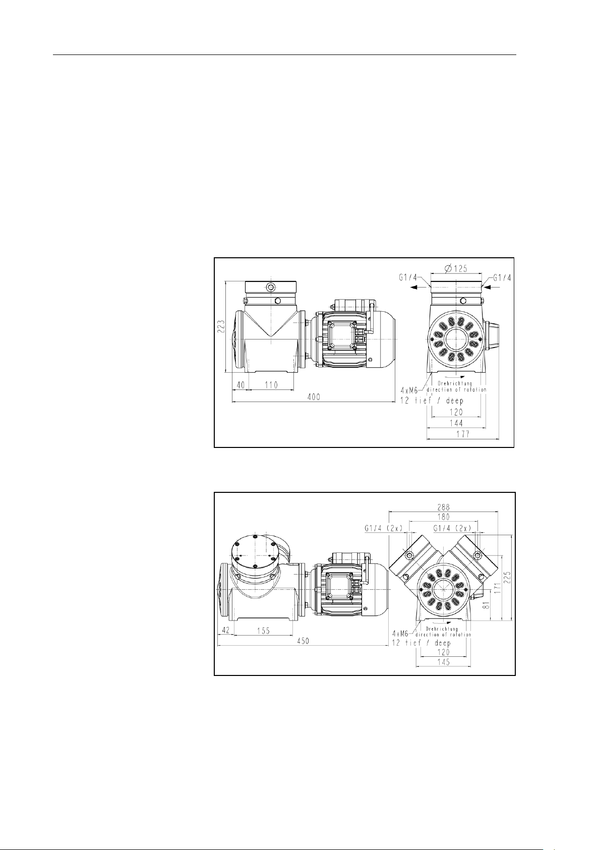
Mounting dimensions
Cooling air supply
6. Installation and connection
Only install the pumps under the operating parameters and conditions described in chapter 4, Technical data.
Observe the safety precautions (see chapter 3).
6.1. Installation of the pump
Before installation, store the pump at the installation location to
bring it up to ambient temperature.
See fig. 5 (pump series N 143__ .12E) and fig. 6 (pump series
N 186.1.2 __.12 E and N 186.3 __.12 E) for the mounting dimensions.
Fig. 5: Mounting dimensions pump series N 143 _ _ .12 E (All dimensional tolerances conform to DIN ISO 2768-1, Tolerance Class V)
Fig. 6: Mounting dimensions pump series N 186.1.2 __.12 E and
N 186.3 __.12 E; shown without pneumatic connections (All dimensional
tolerances conform to DIN ISO 2768-1, Tolerance Class V)
Install the pump so that the motor fan can intake sufficient
cooling air.
14 Translation of original Operating and Installation Instructions, english, KNF 121610-121613 07/16

Diaphragm Pumps N 143/186.12 Installation and connection
The IP protection class of the pump motor is indicated on the
type plate.
DANGER
Extreme danger from electrical shock
Only have the pump connected by an authorized
specialist.
Only have the pump connected when the power
supply is disconnected.
For operating current see type plate.
The voltage must not vary by more than + 10% and - 10% from
that shown on the type-plate.
Installation location
Disengaging
Make sure that the installation location is dry and the pump is
protected against rain, splash, hose and drip water.
Install the pump at the highest point in the system to prevent
condensate from collecting in the pump head.
Protect the pump from dust.
Protect the pump from vibrations and jolts.
KNF recommends mechanically disengaging the pump from
the piping system. This can be achieved with flexible tubing or
pipes, for example. This will avoid transferring to the system
any pump oscillations that may arise.
6.2. Electrical connection
When connecting the device to a power source, the relevant
standards, directives, regulations, and technical standards
must be observed.
In the electrical installation, arrangements (complying with EN
60335-1) must be made for disconnecting the pump motor
from the electrical supply.
The motors of the pump must be protected according to EN
60204-1 (protection against excess current, or overloading).
It is recommended that an additional “Emergency Stop” switch
is installed.
The pump must be installed so that contact with live parts
(electrical connection) is impossible.
Connecting pump
1. Compare the supply data with the data on the motor-plate. For
operating current see type plate.
2. Open terminal box cover.
3. All pumps except versions with 3 phase motor:
Connect the mains cables to the connections L1 and N of the
pump motor.
Translation of original Operating and Installation Instructions, english, KNF 121610-121613 07/16 15

Installation and connection Diaphragm Pumps N 143/186.12
A marking on the pump head shows the direction of flow.
Connected
components
Pressure relief device
Pump exhaust
4. Connection of pumps with 3 phase motor according to figs. 7
or 8.
Fig. 7: Y-Connection (high voltage)
Fig. 8: ∆-Connection (low voltage)
5. Connect the earth (ground) wire to the motor.
6. Close the terminal cover box.
6.3. Pneumatic connection
Only connect components to the pump which are designed for
the pneumatic data of the pump (see chapter 4, Technical data).
Protect the compressors with a pressure relief device between
the pressure side of the compressor and the first shut-off valve.
If the pump is used as a vacuum pump, safely discharge the
pump exhaust at the pump’s pneumatic outlet.
Connecting pump
1. Remove the protective plugs from the hose connection
threads.
2. Connect the suction line and pressure line (see chapter 4,
table 9 for the mounting dimensions).
3. Lay the suction and pressure line at a downward angle to
prevent condensate from running into the pump.
16 Translation of original Operating and Installation Instructions, english, KNF 121610-121613 07/16

Diaphragm Pumps N 143/186.12 Installation and connection
WARNING
Danger of dangerous gas mixtures during operation
of the pump if the working diaphragm ruptures.
Depending on the medium being pumped, a rupture
of the working diaphragm may produce a potentially
dangerous mixture when the medium mixes with the
air in the innerspace between the working diaphragm
and the safety diaphragm.
Evacuate the innerspace between the working
diaphragm and the safety diaphragm (see position 5 in Fig. 4, p. 12) through the two holes in
the pump head (thread size G1/8).
KNF recommends monitoring the pressure of the
evacuated innerspace between the working diaphragm and the safety diaphragm. Immediately
stop the pump if the pressure becomes elevated.
Immediately stop the pump if the working dia-
phragm ruptures. The working diaphragm and
the safety diaphragm must be replaced before
continuing with operation (see chapter 8,
Maintenance).
6.4. Evacuate diaphragm’s innerspace and install
monitoring device
Translation of original Operating and Installation Instructions, english, KNF 121610-121613 07/16 17

Operation Diaphragm Pumps N 143/186.12
WARNING
Hazard of the pump head bursting due to excessive
pressure increase
Do not exceed max. permissible operating
pressure (see chapter 4, Technical data).
Monitor pressure during operation.
If the pressure exceeds the maximum permissi-
ble operating pressure, immediately switch off
pump and eliminate fault (see chapter 9. Troubleshooting).
Only throttle or regulate the air or gas quantity in
the suction line to prevent the maximum permissible operating pressure from being exceeded.
If the air or gas quantity in the pressure line is
throttled or regulated, make sure that the maximum permissible operating pressure is not exceeded.
Ensure that the pump outlet is not closed or
constricted.
Excessive pressure (with all of the related hazards) can be
prevented by placing a bypass line with a pressure-relief valve
between the pressure and suctions sides of the pump. For
further information, contact our technical adviser (see front
page for telephone number).
7. Operation
Only operate the pumps under the operating parameters and
conditions described in chapter 4, Technical data.
Make sure the pumps are used properly (see chapter 2.1).
Make sure the pumps are not used improperly (see chapter
2.2).
Observe the safety precautions (see chapter 3).
The pumps are intended for installation. Before putting them
into service it must be established that machinery or equipment
in which they are installed meets the relevant regulations.
18 Translation of original Operating and Installation Instructions, english, KNF 121610-121613 07/16

Diaphragm Pumps N 143/186.12 Operation
DANGER
Dangerous gas mixtures may form if the working
diaphragm ruptures
If the working diaphragm ruptures, the medium will
mix with the air located in the innerspace between
the working diaphragm and the safety diaphragm.
If the working diaphragm ruptures, stop the
pump immediately. By monitoring the innerspace
between the working diaphragm and the safety
diaphragm, rupture of the working diaphragm
can be detected on the basis of a change in
pressure in the innerspace. Even if the pressure
or flow rate of the pump changes without any
apparent cause, this too can mean that the working diaphragm is ruptured.
The working diaphragm and the safety dia-
phragm must be replaced before continuing with
operation (see chapter 8, Maintenance).
WARNING
Automatic starting can cause personal injury and
pump damage
When the operation of the pump is interrupted by the
thermal switch, the pump will restart automatically
after cooling down.
Take all necessary care to prevent this leading
to a dangerous situation.
The pump may not start up against pressure or vacuum during
switch-on. This also applies in operation following a brief power
failure. If a pump starts against pressure or vacuum, it may
block. This activates the thermal switch, and the pump
switches off.
Pump standstill
Vapors as media
With the pump at a standstill, open pressure and suction lines
to normal atmospheric pressure.
Make sure that normal atmospheric pressure is present in the
lines during switch-on.
Translation of original Operating and Installation Instructions, english, KNF 121610-121613 07/16 19
The life of the diaphragm is prolonged if the formation of condensate is avoided. Therefore the following precautions should be
taken:
Run the pump for a few minutes to warm it up before handling
saturated or nearly saturated vapours.
KNF recommends: When transferring aggressive media, flush
the pump prior to switch-off (see chapter 8.2.1) to increase the
service life of the diaphragm.

Servicing Diaphragm Pumps N 143/186.12
Component
Servicing interval
Pump
- Regular inspection for external dam-
age or leaks
Tube connection
- Regular inspection for external dam-
age or leaks
Working diaphragm,
safety diaphragm
and valve plate
- Replace if the pressure in innerspace
(evacuated) between the working diaphragm and the safety diaphragm decreases (working diaphragm has broken)
- Replace if pump's pressure or flow
rate change without apparent reason
- Replace at the latest, when pump
output decreases
WARNING
There is the danger that hazardous gas mixtures will
form and that the pumped media will leak from the
pump while the pump is in operation, if the safety
diaphragm is not replaced at the same time as the
working diaphragm.
Always replace the safety diaphragm at the
same time the working diaphragm is replaced.
Conditions
Information on procedure
8. Servicing
8.1. Servicing schedule
Tab. 13
8.2. Cleaning
8.2.1. Flushing pump
KNF recommends: When transferring aggressive media, flush
the pump under atmospheric conditions some minutes with air
(or, if necessary for safety reasons, with an inert gas) prior to
switch-off to increase the service life of the diaphragm.
8.2.2. Cleaning pump
Only use solvents for cleaning if the head materials cannot be
attacked (check the resistance of the material).
If compressed air is available, blow out the components.
8.3. Replacing working diaphragm, safety diaphragm and valve plate
Motor disconnected from mains and de-energized
Pump clean and free of dangerous substances
Tubes/pipes removed from pump’s pneumatic inlet and
outlet
Always replace working diaphragm and safety diaphragm
20 Translation of original Operating and Installation Instructions, english, KNF 121610-121613 07/16
together to maintain performance and safety of the pump.

Diaphragm Pumps N 143/186.12 Servicing
WARNING
Health hazard due to dangerous substances
in the pump!
Depending on the substance transferred, caustic
burns or poisoning are possible.
Wear protective clothing if necessary, e.g.
protective gloves.
Clean pump with suitable measures.
Spare part*
Position**
Quantity
Safety diaphragm
(S)
1 (per pump
head)
Working diaphragm
(L)
1 (per pump
head)
O-Ring
(F, H, P)
3 (per pump
head)
O-Ring
(R)
1 (per pump
head)
O-Ring
(T)
1 (per pump
head)
Valve plate
(G)
1 (per pump
head)
Quantity
Tools/Material*
1
Allen key 3
1
Allen key 4
1
Allen key 5
1
Screwdriver blade width 5.5 mm
1
Adjustable pin-wrench for two-hole nuts, pin dia. 4
mm, length of wrench ca. 160 mm (available as
´wrench for retainer plate´, a KNF accessory, see
chapter 10)
8
Retaining clips for assembling of intermediate ring,
intermediate plate and head plate (see „Assembling“,
steps 4, 10 and 13)
1
Felt-tip pen
Spare parts
Tools and material
With multi-head pumps, parts of the individual pump heads can be
confused.
Replace working diaphragm, safety diaphragm and valve plate
of the individual pump heads consecutively.
Tab. 14 * according to spare parts list, chapter 10
** According to Fig. 9.
Tab. 15 * according to accessories list, chapter 10
Translation of original Operating and Installation Instructions, english, KNF 121610-121613 07/16 21

Servicing Diaphragm Pumps N 143/186.12
A Housing
B Intermediate ring
C Intermediate plate
D Head plate
E Hexagon socket head cap
screw
F O-ring
G Valve plate
H O-ring
I Retainer plate
K Hexagon socket head cap
screw
L Working diaphragm
M Hexagon socket head cap
screw
N Diaphragm support
P O-ring
R O-ring
S Safety diaphragm
T O-ring
Z Dowel pin/Roll pin
The following item numbers refer to Fig. 9, unless otherwise
indicated.
Fig. 9: Pump parts
Disassembling
1. Take the steps necessary to gain access to the motor cooling
fan:
Undo the screws that hold the fan cover. For one-headed
pumps: Fig. 1/7, p. 11; for two-headed pumps: Fig. 2/7, p. 11
or Fig. 3/7, p. 12 and remove the fan cover.
22 Translation of original Operating and Installation Instructions, english, KNF 121610-121613 07/16

Diaphragm Pumps N 143/186.12 Servicing
If the retainer plate cannot be loosened, because the dia-
phragm support (N) turns with it, carry out step 7 first. In that
case clamp the diaphragm support to loosen the retainer plate.
2. Only for two-headed pumps.
Remove the pneumatic connection (.3 models), or connections
(.1.2 models) between the pump heads, loosen the union nuts
(Fig. 1/8, p. 11 or Fig. 2/8, p. 11 or Fig. 3/8, p. 12) to do so.
3. Mark the position of head plate (D), intermediate plate (C),
intermediate ring (B) and housing (A) relative to each other by
a drawing line with a felt-tip pen. This helps avoid incorrect assembly later.
4. Undo the six hexagon socket head cap screws (E); lift off head
plate (D) and intermediate plate (C) with valve plate (G); remove valve plate from intermediate plate.
5. Remove the O-ring (F) from the head plate (D); remove the Oring (H) from the intermediate plate.
6. To undo the retainer plate (J), use the wrench for retainer plate
to turn it anti-clockwise; remove retainer plate and working diaphragm (L).
7. Undo the six hexagon socket head cap screws (M); remove
intermediate ring (B).
8. Remove the O-ring (P) from the intermediate ring (B).
9. Undo the hexagon socket head cap screw (K); remove the
diaphragm support (N).
10. Remove the O-rings (R) and (T) from the diaphragm support
(N).
11. Remove safety diaphragm (S).
12. Inspect all parts for dirt and clean them if necessary.
Assembling
1. Press the beaded edge of the new safety diaphragm (S) into
the groove in the diaphragm support (N).
2. Fit a new O-ring (T) in the shaft of the diaphragm support (N).
3. Push the diaphragm support (N) into the connecting rod and
secure it with head cap screw (K).
4. Fit the new O-ring (P) in intermediate ring (B); secure the Oring with retaining clips so that it cannot fall out during assembly.
5. Make certain that the outer edge of safety diaphragm (S) is
seated on the housing (A); now place intermediate ring (B) on
the housing (A) according to the marks made previously; tighten the screws (M) lightly.
6. Now remove the retaining clips, and tighten the screws (M)
diagonally hand-tight.
Translation of original Operating and Installation Instructions, english, KNF 121610-121613 07/16 23

Servicing Diaphragm Pumps N 143/186.12
WARNING
Before putting the pump into operation again,
check and ensure the gas-tightness of the pump
head and the tubing.
7. Fit the new O-Ring (R) in the diaphragm support (N).
8. Turn the fan until the connecting rod is in mid-stroke; place the
new working diaphragm (L) on the intermediate ring (B) and
diaphragm support (N).
9. Place the retainer plate (J) on working diaphragm; to tighten
the retainer plate, use the wrench for retainer plate.
10. Fit the new O-ring (H) in the intermediate plate (C); secure the
O-ring with retaining clips, so that it cannot fall out during assembly.
11. Place intermediate plate (C) on intermediate ring (B) according
to the mark made previously (at the same time, keep the diaphragm in its midposition by holding the motor fan).
12. Fit a new valve plate (G) in the recess in the intermediate plate
(C). A dowel pin/roll pin (Z) determines the correct orientation
of the intermediate plate.
13. Fit a new O-ring (F) in the diaphragm head (D); secure the Oring with retaining clips, so that it cannot fall out during assembly.
14. Place head plate (D) on intermediate plate (C) in the position
given by the dowel pin/roll pin and the mark made previously.
15. Tighten the hexagon socket head cap screws (E) lightly.
16. Now remove the clips from intermediate plate (C) and diaphragm head (D), and tighten the screws (E) uniformly and diagonally (hand-tight).
17. Turn the fan to check that the pump rotates freely.
18. For two-headed pumps: Carry out steps 3. to 9.of disassembling as well as 1.-17.of assembling for the second pump head.
19. For two-headed pumps: Remount the pneumatic connection(s)
between the pump heads.
20. Remount fan cover. For one-headed pumps: Fig. 1/7, p. 11; for
two-headed pumps: Fig. 2/7, p. 11 or Fig. 3/7, p. 12.
21. Check and ensure the gas-tightness of the pump head/pump
heads and the tubing:
24 Translation of original Operating and Installation Instructions, english, KNF 121610-121613 07/16

Diaphragm Pumps N 143/186.12 Troubleshooting
DANGER
Extreme danger from electrical shock!
Disconnect the pump power supply before working
on the pump.
Make sure the pump is de-energized and secure.
Pump does not transfer
Cause
Fault remedy
Pump is not connected with the
power source.
Connect pump with the power source.
No voltage in the power source
Check room fuse and switch on if necessary.
Thermal switch has operated
following to over-heating.
Disconnect pump from mains.
Allow pump to cool.
Trace cause of over-heating and eliminate it.
Connections or lines blocked.
Check connections and lines.
Remove blockage.
External valve is closed or filter
is clogged.
Check external valves and filters.
Condensate has collected in
pump head.
Detach the condensate source from the pump.
Flush the pump under atmospheric conditions some minutes
with air (if necessary for safety reasons: with an inert gas).
Working diaphragm or valve
plate are worn.
Replace working diaphragm, safety diaphragm andvalve
plate (see chapter 8.3).
Flow rate, pressure or vacuum too low
The pump does not achieve the output specified in the Technical data or the data sheet.
Cause
Fault remedy
Working diaphragm has broken.
Immediately shut down pump.
Check whether the pressure in innerspace (evacuated)
between working diaphragm and safety diaphragm has elevated. If the pressure has elevated, replace working diaphragm and safety diaphragm (see chapter 8) before further
operating the pump.
Condensate has collected in
pump head.
Detach the condensate source from the pump.
Flush the pump under atmospheric conditions some minutes
with air (if necessary for safety reasons: with an inert gas).
There is gauge pressure on
pressure side and at the same
time vacuum or a pressure
above atmospheric pressure on
suction side.
Change the pressure conditions.
Pneumatic lines or connection
parts have an insufficient cross
section.
Disconnect pump from system to determine output values.
Eliminate throttling (e.g. valve) if necessary.
Use lines or connection parts with larger cross section if
necessary.
9. Troubleshooting
Check the pump (see Tab. 16 and 17).
Tab. 16
Translation of original Operating and Installation Instructions, english, KNF 121610-121613 07/16 25

Troubleshooting Diaphragm Pumps N 143/186.12
Flow rate, pressure or vacuum too low
The pump does not achieve the output specified in the Technical data or the data sheet.
Cause
Fault remedy
Leaks occur on connections,
lines or pump head.
Eliminate leaks.
Connections or lines completely
or partially jammed.
Check connections and lines.
Remove the jamming parts and particles.
Head parts are soiled.
Clean head components.
Working diaphragm or valve
plate is worn.
Replace working diaphragm, safety diaphragm and valve
plate(see chapter 8.3).
Tab. 17
Fault cannot be rectified
If you are unable to determine any of the specified causes, send
the pump to KNF Customer Service (see last page for the address).
1. Flush the pump under atmospheric conditions some minutes
with air (if necessary for safety reasons: with an inert gas) to
free the pump head of dangerous or aggressive gases (see
chapter 8.2.1).
2. Clean the pump (see chapter 8.2.2).
3. Send the pump, together with completed Health and Safety
Clearance and Decontamination Form (Chapter 12), to KNF
stating the nature of the transferred medium.
26 Translation of original Operating and Installation Instructions, english, KNF 121610-121613 07/16

Diaphragm Pumps N 143/186.12 Spare parts and accessories
Spare part
Position*
Order No.
Working diaphragm
(L)
001620
Safety diaphragm
(S)
001622
Valve plate
(G)
001615
O-ring
(F, H, P)
002445
O-ring
(R)
002433
O-ring
(T)
002431
Spare part
Position*
Order No.
Working diaphragm
(L)
001904
Safety diaphragm
(S)
001906
Valve plate
(G)
001908
O-ring
(F, H, P)
002460
O-ring
(R)
002450
O-ring
(T)
002448
Accessories
Order No.
Wrench for retainer plate
018816
10. Spare parts and accessories
Spare Parts
N 143 AN.12 E N 143 SN.12 E
N 186.1.2 AN.12 E N 186.1.2 SN.12 E
N 186.3 AN.12 E N 186.3 SN.12 E
Tab. 18 *according to Fig. 9
N 143 AV.12 E N 143 SV.12 E
N 186.1.2 AV.12 E N 186.1.2 AV.12 E
N 186.3 AV.12 E N 186.3 AV.12 E
Tab. 19 * according to Fig. 9
Accessories
Tab. 20
Translation of original Operating and Installation Instructions, english, KNF 121610-121613 07/16 27

Returns Diaphragm Pumps N 143/186.12
11. Returns
Pumps and systems used in laboratories and process-based
industries are exposed to a wide variety of conditions. This means
that the components contacting pumped media could become
contaminated by toxic, radioactive, or otherwise hazardous substances.
For this reason, customers who send any pumps or systems back
to KNF must submit a Health and safety clearance and decontamination form in order to avoid a hazardous situation for KNF employees. This Health and safety clearance and decontamination
form provides the following information, among other things:
physiological safety
whether medium-contacting parts have been cleaned
whether the equipment has been decontaminated
media that have been pumped or used
To ensure worker safety, work may not be started on pumps or
systems without a signed Health and safety clearance and decontamination form.
For optimal processing of a return, a copy of this declaration
should be sent in advance via e-mail, regular mail, or fax to KNF
Customer Service (refer to final page for address). In order to avoid
endangering employees who open the shipment's packaging,
despite any residual hazards, the original version of the Health and
safety clearance and decontamination form must accompany the
delivery receipt on the outside of the packing.
The template for the Health and safety clearance and decontamination form is included with these operating instructions and may
also be downloaded from the KNF website.
The customer must specify the device type(s) and serial number(s)
in the Health and safety clearance and decontamination form in
order to provide for the unambiguous assignment of the Declaration to the device that is sent to KNF.
In addition to the customer's declaration of physiological safety,
information about operating conditions and the customer's application are also of importance to ensure that the return shipment is
handled appropriately. Therefore, the Health and safety clearance
and decontamination form requests this information as well.
28 Translation of original Operating and Installation Instructions, english, KNF 121610-121613 07/16

Health and safety clearance and decontamination form Diaphragm Pumps N 143/186.12
12. Health and safety clearance and decontamination form
29 Translation of original Operating and Installation Instructions, english, KNF 121610-121613 07/16


KNF worldwide
Find your local KNF partner on www.knf.com
 Loading...