


KNF 308918-308921 03/19
OEM
N 0150
TRANSLATION OF ORIGINAL OPERATING AND
INSTALLATION INSTRUCTION
ENGLISH
DIAPHRAGM PUMP
Note!
Before operating the pump and the accessories, please read the operating and installation instructions and
pay attention to the safety precautions!

KNF Neuberger GmbH
Alter Weg 3
79112 Freiburg
Germany
Phone +49-(0)7664/5909-0
Fax. 07664/5909-99
Email: info@knf.de
www.knf.com
Index
1 About this document ......................................................... 3
2 Use ...................................................................................4
3 Safety................................................................................ 5
4 Technical data ..................................................................7
5 Design and function ........................................................ 10
6 Transport ........................................................................13
7 Installation and connection ............................................. 15
8 Operation ........................................................................ 22
9 Servicing ......................................................................... 25
10 Troubleshooting .............................................................. 31
11 Spare parts and accessories ..........................................33
12 Returns ...........................................................................34
13 Appendix.........................................................................35

Diaphragm Pump N 0150 About this document
1 About this document
1.1 Using the operating and installation instructions
The operating and installation instructions are part of the pump.
à
The individual chapters of these operating and installation instructions
make reference to the operating instructions of the motor manufacturer
for capacitor and three-phase motors. They are appended to these operating and installation instructions.
à
Give the operating and installation instructions to the next owner.
à
Keep the operating and installation instructions within reach at all
times.
Project pumps For customer-specific project pumps (pump models that begin with "PJ" or
"PM"), there may be deviations from the operating and installation instructions.
à
For project pumps, also observe the agreed specifications.
1.2 Symbols and markings
Warning notice
A notice that warns you of danger is located here.
Possible consequences of a failure to observe the
warning notice are specified here. The signal
WARNING
word, e.g., warning, indicates the danger level.
à Measures for avoiding the danger and its
consequences are specified here.
Danger levels
Signal word Meaning Consequences if not
observed
DANGER warns of immediate
danger
WARNING warns of possible dan-
ger
CAUTION warns of a possibly
dangerous situation
Tab.1
Other notices and symbols
Death or serious injury
or serious damage will
result.
Death or serious injury
or serious damage are
possible.
Minor injuries or damage are possible.
à
An activity to be carried out is specified here (a step).
1. The first step of an activity to be carried out is specified here.
This symbol indicates important information.
Translation of Original operating and installation instruction, English, KNF 308918-308921 03/19
3

Use Diaphragm Pump N 0150
2 Use
2.1 Proper use
The pumps are intended exclusively for transferring gases and vapors.
Responsibility of the owner
Operating parameters and
conditions
Requirements for the transferred
medium
Frequency converter Pumps with three-phase motor are designed for operation with frequency
Only install and operate the pumps in accordance with the operating parameters and conditions described in Chapter 4 Technical data.
Protect compressors with a pressure relief device between the pressure
side of the compressor and the first shut-off valve.
Only fully assembled pumps may be operated.
Make sure that the installation location is dry and that the pump is protected against rain, splash, gushing and drip water as well as from other
contaminants.
The tightness of the connections between the pipes of the application and
the pump (or the connection of the pump) is to be checked at regular intervals. Leaky connections carry the risk of releasing dangerous gases and
vapors from the pump system.
Before transferring a medium, check whether the medium can be transferred danger-free in the specific application.
Before using a medium, check the compatibility of the media-contacting
components (see 4 Technical data) with the medium.
Risk of dangerous gas mixtures during pump operation if diaphragm
breaks: Depending on the medium being transferred, breakage of the diaphragm can result in a dangerous mixture if the medium mixes with the
air in the compressor housing.
Only transfer gases that remain stable under the pressures and temperatures that arise in the pump.
converter in the speed range 500 – 1500 rpm (50 Hz) or 600 – 1600 rpm
(60 Hz) (see also Chapter 7.2 Electrical connection).
2.2 Improper use
The pumps may not be operated in explosive atmospheres.
The pumps are not suitable for transferring:
§
Dusts
§
Liquids
§
Aerosols
§
Biological and microbiological substances
§
Fuel
§
Explosives and flammable material
§
Fibers
§
Oxidants
§
Food
Pumps that can produce both vacuum as well as overpressure may not be
used to simultaneously produce vacuum and operating pressure.
No operating pressure may be applied to the suction side of the pump.
Pumps with capacitor motor are not intended for operation with a frequency converter.
4 Translation of Original operating and installation instruction, English, KNF 308918-308921 03/19

Diaphragm Pump N 0150 Safety
3 Safety
Observe the safety notices in chapters 7 Installation and connection
and 8.1 Operation.
The pumps are built in accordance with the generally recognized rules of
technology and the occupational safety and accident prevention regulations. Nevertheless, dangers can arise during their use that lead to injuries
to the user or third parties or to damage to the pump or other property.
Only use the pumps in perfect technical condition, for their intended use,
safely and aware of the dangers and in observation of the operating and
installation instructions.
The components that are to be connected to the pumps must be designed
according to the pneumatic data of the pumps.
When connecting the pumps to the electrical mains, observe the corresponding safety rules.
Personnel Make sure that only trained and instructed personnel or specially trained
personnel work on the pumps. This applies, in particular, to assembly, connection and servicing work.
Make sure that the personnel have read and understood the operating and
installation instructions, particularly the chapter on safety.
Working in a safety conscious
manner
Working with hazardous media Upon breakage of the diaphragm and/or leaks, the transferred medium
Working with combustible media Note that the pumps are not designed to be explosion-proof.
Environmental protection Store and dispose of all replacement parts in accordance with environmen-
Observe the regulations on accident prevention and safety during all work
on the pumps and during operation.
The pump heads heat up during operation; therefore avoid contact with
them.
Make certain that the pump is disconnected from mains and without
power.
Make sure that no dangers arise from flow when gas connections are
open, from noises or from hot, corrosive, dangerous and environmentally
hazardous gases.
Make sure that an EMC-compliant installation of the pump is ensured at all
times and that no dangerous situation can thereby arise.
mixes with the air in the surroundings and/or in the pump housing. Make
sure that a dangerous situation cannot arise as a result.
When transferring hazardous media, observe the safety regulations for the
handling of these media.
Make sure that the temperature of the medium is always sufficiently below
the ignition temperature of the medium so as to prevent ignition or explosion. This also applies for abnormal operating situations.
Note here that the temperature of the medium increases when the pump
compresses the medium.
Therefore, make sure that the temperature of the medium also remains
sufficiently below the ignition temperature of the medium even when it is
compressed to the maximum permissible operating pressure of the pump.
The maximum permissible operating pressure of the pump is stated in the
technical specifications (4 Technical data).
If applicable, also take into consideration external energy sources (e.g., radiation sources) that could add heat to the medium.
In case of doubt, contact KNF Customer Service.
tal regulations. Observe the respective national and international regulations. This applies in particular to parts that are contaminated with toxic
substances.
Translation of Original operating and installation instruction, English, KNF 308918-308921 03/19
5

Safety Diaphragm Pump N 0150
EU/EC directives/standards With respect to the Machinery Directive 2006/42/EC, the pumps are partly
completed machinery and are, therefore, to be regarded as not ready for
use. Partly completed machinery may not be commissioned until it has
been determined that the machine into which the partly completed machinery is to be installed complies with the provisions of the Machinery Directive 2006/42/EC. The following fundamental requirements of Annex I of Directive 2006/42/EC (general principles) are applied and observed:
§
General principles no. 1
§
No. 1.1.2. / 1.1.3. / 1.3.1. / 1.3.3. / 1.3.4. / 1.4.1. / 1.5.1. / 1.5.2. /
1.5.8. / 1.5.9. / 1.7.4. / 1.7.4.1. / 1.7.4.3.
As these partly completed machines are built-in devices, the mains connections and equipment for disconnecting and switching off the partly completed machinery as well as overcurrent and overload protection gear must
be considered when mounting.
Furthermore, protection against contact with moving and hot parts, if
present, must be provided during installation.
The pumps comply with Directive 2011/65/EC (RoHS2).
The following harmonized standards are satisfied:
§ DIN EN 60034-1/5/6/9
§ DIN EN 60204-1
§ DIN EN 61000-6-1/2/3/4
§ DIN EN 50581
§ EN 60034-30-1 (only pumps with three-phase motor)
Customer service and repairs The pumps are maintenance-free. KNF does, however, recommend peri-
odically inspecting the pumps for noticeable changes to noises and vibrations.
Only have repairs to the pumps performed by the responsible KNF Customer Service.
Housings with live components may only be opened by specialist personnel.
Use only original parts from KNF during servicing work.
6 Translation of Original operating and installation instruction, English, KNF 308918-308921 03/19

Diaphragm Pump N 0150 Technical data
4 Technical data
4.1 Technical data
Pump materials
N 0150
N 0150.3
Assembly MaterialAPMaterialSPMaterial
ST
Head plate, intermediate plate Aluminum Stainless
steel
Diaphragm EPDM EPDM PTFE-
Reed valves/valve stopper Stainless
steel
Retainer plate Stainless
steel
O-rings EPDM EPDM FPM
Pneumatic head connection (only
N 0150.3)
Tab.2
Steel Stainless
Stainless
steel
Stainless
steel
steel
Stainless
steel
coated
Stainless
steel
Stainless
steel
Stainless
steel
Pneumatic values
Parameter Value
N 0150APE
N 0150SPE
Max. permissible operating pressure
[bar rel*]
Ultimate vacuum [mbar abs.] 120 130
Flow rate at atm. pressure [l/
min]**
Tab.3 *Bar rel related to 1013 hPa
**Liters in standard state (1013 hPa, 20°C)
Parameter Value
Max. permissible operating pressure
[bar rel*]
Ultimate vacuum [mbar abs.] 25 30
Flow rate at atm. pressure [l/
min]**
Tab.4 *Bar rel related to 1013 hPa
**Liters in standard state (1013 hPa, 20°C)
1.0 1.0
130 ± 10% 100 ± 10%
N 0150.3APE
N 0150.3SPE
0.5 0.5
130 ± 10% 100 ± 10%
Value
N 0150STE
Value
N 0150.3STE
Translation of Original operating and installation instruction, English, KNF 308918-308921 03/19
7

Technical data Diaphragm Pump N 0150
Pneumatic connections
Pump type Value
N 0150 Thread size G 1/4*
N 0150.3 Thread size G 1/4*
Tab.5 *Acc. to ISO 228
Electrical data for pumps with capacitor motor
N 0150
Parameter Value Value Value Value
Voltage [V]* 100 115 220 230
Frequency [Hz]* 50/60 60 60 50
Power P1 [W] ** ** ** 900
Current consumption [A] ** ** ** 7.8
Motor protection class See motor type plate
Max. permissible mains
See operating instructions for motor
voltage fluctuations
Tab.6 *For further voltage and frequency variants, see type plate
**See type plate
N 0150.3
Parameter Value Value Value Value
Voltage [V]* 100 115 220 230
Frequency [Hz]* 50/60 60 60 50
Power P1 [W] 1200 1000 ** 1000
Current consumption [A] 5 8.5 ** 9.3
Motor protection class See motor type plate
Max. permissible mains
See operating instructions for motor
voltage fluctuations
Tab.7 *For further voltage and frequency variants, see type plate
**See type plate
Electrical data for pumps with three-phase motor
N 0150
Parameter Value Value Value Value
Voltage [V]* 200/346 277/480 220/380 230/400
Frequency [Hz]* 50/60 60 60 50
Power P1 [W] ** ** ** 900
Current consumption [A] ** ** ** 6.1/3.5
Motor protection class See motor type plate
Max. permissible mains
See operating instructions for motor
voltage fluctuations
Tab.8 *For further voltage and frequency variants, see type plate
**See type plate
8 Translation of Original operating and installation instruction, English, KNF 308918-308921 03/19

Diaphragm Pump N 0150 Technical data
N 0150.3
Parameter Value Value Value Value
Voltage [V]* 200/346 277/480 220/380 230/400
Frequency [Hz]* 50/60 60 60 50
Power P1 [W] ** ** ** 900
Current consumption [A] ** ** ** 6.1/3.5
Motor protection class See motor type plate
Max. permissible mains
See operating instructions for motor
voltage fluctuations
Tab.9 *For further voltage and frequency variants, see type plate
**See type plate
Weight
Pump type Weight (kg)
Three-phase
Weight (kg)
Capacitor motor
motor
N 0150APE Approx. 34.5 Approx. 40.5
N 0150SPE
Approx. 40.5 Approx. 46.5
N 0150STE
N 0150.3APE Approx. 41.5 Approx. 46.5
N 0150.3SPE
Approx. 53.5 Approx. 58.5
N 0150.3STE
Tab.10
Other parameters
Parameter Value
Permissible ambient temperature + 5°C to + 40°C
Permissible media temperature + 5°C to + 40°C
Max. surface temperature* + 85°C
Dimensions
N 0150
N 0150.3
See Chapter 7.1 Installing the pump
Fig. 9
Fig. 8
Gas tightness** of the pump head
(Leak rate):
N 0150 _P.9 E/ N 0150.3_P.9 E/ N
< 6 x 10⁻³ mbar l/s***
0150 ST.9 E/ N0150.3ST.9E
N 0150 SP.13 E/ N 0150.3SP.13 E
< 6 x 10⁻⁶ mbar l/s***
N 0150 ST.13 E/ N 0150.3ST.13E
Highest permissible relative air humidity of the environment
Maximum installation altitude [m
< 6 x 10⁻⁵ mbar l/s***
80% for temperatures to 31°C, decreasing linearly to 50% at 40°C.
See operating instructions for motor
above sea level]
Protection class of pump:
N 0150
N 0150.3
Tab.11 *To reduce the surface temperature of the pump heads and to extend the
service life of the diaphragm, you can optionally attach a water cooling system (see
Chapter 7.4 Connecting water cooling (optional)).
**The gas tightness of the pump head is no longer ensured after the pump head is
opened or after changing diaphragm and reed valves. A leak test can be used to
determine whether the original gas tightness is again achieved.
***Values apply for helium leak test
IP 20
IP 20
Translation of Original operating and installation instruction, English, KNF 308918-308921 03/19
9

Design and function Diaphragm Pump N 0150
1
2 3
4
5
1
2
3
4
5
5 Design and function
Design
1 Pneumatic pump outlet
2 Pneumatic pump inlet
3 Electrical terminal box
4 Motor
5 Motor fan cover
1 Pneumatic pump outlet
2 Pneumatic pump inlet
3 Electrical terminal box
4 Motor
5 Motor fan cover
Fig.1 Diaphragm pump N 0150 (three-phase motor)
Fig.2 Diaphragm pump N 0150 (capacitor motor)
10 Translation of Original operating and installation instruction, English, KNF 308918-308921 03/19

Diaphragm Pump N 0150 Design and function
5
4
6
3
2 2
7
1
5
6
4
3
2
2
7
1
1 Pneumatic pump outlet
2 Union nut
3 Pneumatic head connec-
tion
4 Motor
5 Motor fan cover
6 Electrical terminal box
7 Pneumatic pump inlet
Fig.3 Diaphragm pump N0150.3 (three-phase motor)
1 Pneumatic pump outlet
2 Union nut
3 Pneumatic head connec-
tion
4 Motor
5 Motor fan cover
6 Electrical terminal box
7 Pneumatic pump inlet
Fig.4 Diaphragm pump N0150.3 (capacitor motor)
Translation of Original operating and installation instruction, English, KNF 308918-308921 03/19
11

Design and function Diaphragm Pump N 0150
Function of a diaphragm pump
1 Outlet valve
2 Inlet valve
3 Transfer chamber
4 Diaphragm
5 Eccentric
6 Connecting rod
7 Pump drive
Fig.5 Function of a diaphragm pump
Diaphragm pumps transfer, compress (depending on the version) and evacuate gases and vapors.
The elastic diaphragm (4) is moved up and down by the eccentric (5) and the
connecting rod (6). In the downwards stroke, it aspirates the gas to be transferred via the inlet valve (2). In the upwards stroke, the diaphragm presses the
medium out of the pump head via the outlet valve (1). The transfer chamber
(3) is hermetically separated from the pump drive (7) by the diaphragm.
12 Translation of Original operating and installation instruction, English, KNF 308918-308921 03/19

Diaphragm Pump N 0150 Transport
6 Transport
General
Personal injury and/or property damage due to incorrect or improper transport of the pump
In the event of incorrect or improper transport, the
CAUTION
CAUTION
pump can fall down, be damaged or injure persons.
àUse suitable auxiliary means if necessary
(carrying strap, lifting gear, etc.).
àWhere appropriate, wear suitable personal
protective equipment (e.g., safety shoes,
safety gloves).
Risk of injury from sharp edges on the packaging
There is a risk of injury from cutting on the sharp
edges when grabbing corners or when opening
the packaging.
à Where appropriate, wear suitable personal
protective equipment (e.g., safety shoes,
safety gloves).
à
Transport the pump in the original packaging to the installation location.
à
Store the original packaging of the pump (e.g., for later storage).
à
Inspect the pump for transport damage after receiving it.
à
Document any transport damage in writing.
à
Remove any transport safeguards on the pump prior to commissioning.
Parameter
Parameter Value
Storage temperature + 5°C to + 40°C
Transport temperature - 10°C to + 60°C
Permissible humidity (non-condensing)
Tab.12
Prior to commissioning, make sure that the pump has reached the
ambient temperature (4 Technical data).
30% to 85%
Translation of Original operating and installation instruction, English, KNF 308918-308921 03/19
13

Transport Diaphragm Pump N 0150
Transport with carrying strap
Fig.6 Position of carrying strap (example)
1. Pull the carrying strap under the pump (see Fig. 6).
Fig.7
2. Fasten the carrying strap between compressor housing and motor
(Fig. 1, see Fig. 7).
3. Make certain that the lifting load cannot be transferred from the belt to
the pump connection.
4. Lift the pump from the packaging with the help of lifting gear.
5. Lower the pump carefully at the installation location.
14 Translation of Original operating and installation instruction, English, KNF 308918-308921 03/19

Diaphragm Pump N 0150 Installation and connection
7 Installation and connection
The pumps are only to be installed in accordance with the operating parameters and conditions described in Chapter 4 Technical data.
Observe safety notices (see Chapter 3 Safety).
7.1 Installing the pump
à
Before installing, store the pump at the installation location to allow it to
reach the ambient temperature.
Mounting dimensions
à
For mounting dimensions, see the following figures:
Fig.8 Mounting dimensions pump series N 0150.3
Translation of Original operating and installation instruction, English, KNF 308918-308921 03/19
15

Installation and connection Diaphragm Pump N 0150
Cooling air supply
Immediate environment of the
hot pump parts
Installation location
Fig.9 Mounting dimensions pump series N 0150
Danger of getting burned by hot surfaces
Hot surfaces could occur if the pump overheats.
à When installing the pump, make sure that
WARNING
à
During installation, make sure that no combustible or thermally deformable objects are positioned in the immediate environment of the
hot pump parts (head, motor).
à
Make sure that the installation location is dry and that the pump is protected against rain, splash, gushing and drip water as well as from
other contaminants.
à
Make sure that the installation location is accessible for maintenance
and service.
à
Make sure that the pump is securely attached to the intended fastening
holes. If necessary, secure pump to base plate with rubber-bonded
metal (see accessories, Chapter 11.2 Accessories; observe details on
pump weight, Chapter 4 Technical data).
sufficient cooling air infeed and discharge is
ensured.
à
Make sure that access to moving parts (such as via the pump housing
from below) is avoided.
The IP protection class of the pump motor is specified on the type
plate.
à
Mount the pump at the highest point in the system to prevent condensate from collecting in the pump head.
à
Protect pump from dust.
à
Protect pump from vibration and impact.
16 Translation of Original operating and installation instruction, English, KNF 308918-308921 03/19

Diaphragm Pump N 0150 Installation and connection
Installation position
Protection against foreign
objects
à
The pump can be mounted in any installation position. Use metal
screws to fasten the pump at the indicated attachment points.
Personal injury and/or property damage from vibrations
Pump vibrations, in combination with adjacent
WARNING
components, can result in crushing and/or damage to these components.
à Make sure that pump vibrations cannot lead
to dangers in combination with adjacent components.
à
Take protective measures against touching and foreign objects which
could enter the pump.
7.2 Electrical connection
Danger to life from electric shock
àOnly have the pump connected by an autho-
rized specialist.
Fastening the connection cables
DANGER
à
When connecting to a power source, observe the applicable standards,
directives, regulations and technical standards.
à
When connecting to a power source, carefully read and observe the
motor operating instructions (including the notice on insulation resistance measurement).
à
Install a device for separating the pump motor from the electrical mains
in the electrical installation (in accordance with EN 60335-1).
à
Protect the pump motors in accordance with EN 60204-1 (overcurrent
protection, overload protection).
Refer to the pump type plate for the max. current consumption.
à
It is recommended that an additional emergency-off system be installed.
à
Mount the pumps in such a way that it is not possible to touch the electrically live parts (electrical connection).
à
Fasten the connection cables so that
– the cables do not come into contact with movable or hot parts.
– the cables cannot be worn or damaged on sharp corners or edges
àOnly have the pump connected if the power
supply is disconnected.
Translation of Original operating and installation instruction, English, KNF 308918-308921 03/19
17

Installation and connection Diaphragm Pump N 0150
– no tensile and pressure forces are exerted on the connection point
of the cables (strain relief)
The three-phase motors are suitable for operation with frequency
converters.
Connecting the pump
1. Compare the data of the supply voltage with the details on the motor
type plate. See the pump type plate for the maximum current consumption of the pump.
For the permissible deviation of the supply voltage, see operating
instructions for motor.
2. Open the terminal box cover.
3. Connect the earth wire to the pump motor.
4. Connect the cables for the electrical voltage according to the operating
instructions for the motor.
Set the direction of rotation according to the arrow on the fan hood
(see 7.1 Installing the pump and operating instructions for the mo-
tor).
5. Close the terminal box cover again.
Connected components
Pressure relief device
Pump discharge
Decoupling
7.3 Pneumatic connection
Personal injury or property damage through
ejected plugs
If not removed, the plugs on the pressure side of
CAUTION
the pump can be ejected by the resulting operating pressure.
à Remove plugs during installation.
à
Only connect components to the pump that are designed for the pneumatic data and thermal requirements of the pump. (see Chapter 4
Technical data).
à
Protect compressors by means of a pressure relief device between the
pressure-side connections of the compressor and the first shut-off
valve.
à
If the pump is used as a vacuum pump, safely (with respect to medium
and noise) drain the hot pump discharge that may, under certain circumstances, occur at the pneumatic outlet of the pump.
à
KNF recommends mechanically decoupling the pump from the pipe
system, e.g., through the use of flexible hoses or pipes. In this way it is
possible to prevent the transfer of possible pump vibrations and noises
to the system.
18 Translation of Original operating and installation instruction, English, KNF 308918-308921 03/19
Diaphragm Pump N 0150 Installation and connection
Connecting the pump
A marking on the pump head indicates the flow direction.
Risk of injury from mixing up suction and pressure
side
Mixing up the suction and pressure side can result
CAUTION
in breakage of connected components on the suction and pressure side.
à Observe the marking of inlet and outlet.
1. Remove protective plugs from the hose connection threads.
2. Connect suction and pressure line (for mounting dimensions, see
Chapter 4 Technical data).
3. Lay the suction and pressure line at a downward angle to prevent condensate from running into the pump.
Pneumatic noises can be reduced or dissipated by using a silencer
(see Chapter 11.2 Accessories).
Secure the pressure-side connections with a fastener (e.g., hose/
pipe clamp) to prevent the hoses from slipping down from the connection.
7.4 Connecting water cooling (optional)
Water cooling (see 11.2 Accessories) can increase the service life
of the diaphragm, particularly with high pressures or high ambient
temperature.
Recommended parameters
Parameter Value
Water temperature + 5°C to + 30°C
Water flow rate [l/min] 1.0
Tab.13
Translation of Original operating and installation instruction, English, KNF 308918-308921 03/19
19

Installation and connection Diaphragm Pump N 0150
Mounting dimensions For mounting dimensions see Fig. 10, Fig. 11 and Fig. 12:
The base plate is shown as an additional accessory on the following
dimensional drawings.
Fig.10 Mounting dimensions pump series N 0150.3
Fig.11 Mounting dimensions pump series N 0150
à
Operate the water connection up to max. 1.0 bar gauge.
20 Translation of Original operating and installation instruction, English, KNF 308918-308921 03/19

Diaphragm Pump N 0150 Installation and connection
à
Safely drain water discharge.
à
Flow in both directions is permissible.
Translation of Original operating and installation instruction, English, KNF 308918-308921 03/19
21
Operation Diaphragm Pump N 0150
8 Operation
8.1 General
Risk of burns from hot pump parts and/or hot
medium
Some pump parts may be hot during or after oper-
WARNING
WARNING
ation of the pump.
àAllow pump to cool after operation.
àTake protective measures to protect against
touching hot parts.
Injury to eyes
Coming too close to the inlet/outlet of the pump
may result in injury to the eyes due to the present
vacuum/operating pressure.
à Do not look into the pump inlet/outlet during
operation.
à
Only operate the pumps in accordance with the operating parameters
and conditions described in Chapter 4 Technical data.
à
Ensure the proper use of the pumps (See Chapter 2.1 Proper use).
à
Eliminate the possibility of improper use of the pumps (see Chapter 2.2
Improper use).
à
Observe safety notices (Chapter 3 Safety).
à
The pumps are built-in devices. Before they are commissioned, it must
be ensured that the machines or systems into which the pumps are installed comply with the relevant provisions.
22 Translation of Original operating and installation instruction, English, KNF 308918-308921 03/19
Diaphragm Pump N 0150 Operation
Risk of bursting of pump head due to excessive
pressure increase
àDo not exceed the maximum permissible op-
WARNING
erating pressure (see 4 Technical data).
àMonitor the pressure during operation.
àIf the pressure exceeds the maximum permis-
sible operating pressure of the pump: immediately switch off the pump and remedy the fault
(see Chapter 10 Troubleshooting).
àOnly throttle or regulate the air or gas quantity
on the suction line to prevent the maximum
permissible operating pressure from being exceeded.
àIf the air or gas quantity on the pressure line is
throttled or regulated, make sure that the maximum permissible operating pressure at the
pump is not exceeded.
àEnsure that the pump outlet is not closed or
restricted.
Excessive pressure, with all of the associated hazards, can be prevented by means of a bypass line with a pressure relief valve between the pressure and suction sides of the pump. Further information is available from the KNF technical adviser (for contact data,
see www.knf.de).
Risk of dangerous gas mixtures during pump operation if the working diaphragm breaks
If the diaphragm should break, the medium will
WARNING
mix with the air in the compressor housing.
à The diaphragm must be replaced prior to fur-
ther operation (see Chapter 9 Servicing).
Personal injury and damage to the pump through
automatic start
If pump operation is interrupted by the thermal
WARNING
switch or the triggering device for the PTC thermistor sensor due to overheating, the pumps resume operation automatically after they have
cooled down.
à Ensure that no dangerous situations can
arise as a result.
Translation of Original operating and installation instruction, English, KNF 308918-308921 03/19
23

Operation Diaphragm Pump N 0150
Operation with open suction-side gas connection can result in contaminants and objects being drawn in.
Pump standstill
Vapors as medium The service life of the diaphragm can be extended by preventing the for-
Switching off/decommissioning
pump
Recommissioning
Inspecting the pump
à
When the pump is at a pump standstill, establish normal atmospheric
pressure in the lines.
The pump must not be started up against pressure or vacuum during switch-on. This also applies during operation after a brief power
failure. If a pump starts up against pressure or vacuum, the pump
may block, thereby activating the thermal switch or triggering device
for the PTC thermistor sensors and switching off the pump.
à
Ensure that normal atmospheric pressure is present in the lines when
switching on.
mation of condensate in the pump. Therefore:
à
Only perform work with saturated or nearly saturated vapors with a
warm pump.
à
KNF recommends: When transferring aggressive media, flush the
pump before switching off (see Chapter 9.2.1 Flushing the pump) to ex-
tend the service life of the diaphragm.
à
Establish normal atmospheric pressure in the lines (relieve pump
pneumatically).
à
Before recommissioning, observe the applicable standards, guidelines,
regulations and technical standards at the electrical connection.
à
Inspect the pump periodically for external damage or leakage.
24 Translation of Original operating and installation instruction, English, KNF 308918-308921 03/19
Diaphragm Pump N 0150 Servicing
9 Servicing
9.1 Servicing schedule
Component Servicing interval
Pump
Hose connections
Diaphragm and reed valves
Tab.14
à
Periodic inspection for external
damage or leakage.
à
Periodic inspection for noticeable changes to noises and vibrations
à
Periodic inspection for external
damage or leakage.
à
Replace no later than if there is
a decrease in the pump flow
rate.
à
Replace if the pressure or flow
rate of the pump changes without apparent reason.
9.2 Cleaning
9.2.1 Flushing the pump
When transferring dangerous and environmentally hazardous media, KNF
recommends flushing the pump at atmospheric pressure for a few minutes
prior to switch-off (if necessary for safety reasons: with an inert gas) to extend the service life of the diaphragm.
à
Discharge the media safely.
9.2.2 Cleaning the pump
Risk of burns from hot pump parts
The pump head or motor may still be hot after operation of the pump.
CAUTION
WARNING
à Allow pump to cool after operation.
Health hazard due to dangerous substances in the
pump
Depending on the medium being transferred,
caustic burns or poisoning is possible.
àWear protective equipment if necessary, e.g.,
protective gloves, goggles.
àClean pump with suitable measures.
During cleaning work, ensure that no fluids enter the interior of the
housing.
à
Solvents should only be used during cleaning if head materials are not
affected (ensure resistance of the material).
Translation of Original operating and installation instruction, English, KNF 308918-308921 03/19
25

Servicing Diaphragm Pump N 0150
à
If compressed air is available, blow out parts.
9.3 Changing diaphragm and reed valves
Requirements
à
Motor disconnected from mains and voltage-free
à
Pump and motor have cooled
à
Pump cleaned and free of hazardous materials
à
Hoses/pipes removed from pneumatic pump inlet and outlet.
With multi-headed pumps, parts may be interchanged between the individual pump heads.
à
Change the parts of the individual pump heads that are to be exchanged one after the next.
Health hazard due to dangerous substances in the
pump
Depending on the medium being transferred,
WARNING
caustic burns or poisoning is possible.
àWear protective equipment if necessary, e.g.,
protective gloves, goggles.
Spare parts
àClean pump with suitable measures.
Risk of burns from hot pump parts
The pump head or motor may still be hot after operation of the pump.
CAUTION
For two-headed pumps:
Servicing work should generally be performed on both heads at the
same time.
Spare part* Position designation** Quantity
Diaphragm (4) 1 (per pump head)
O-ring (2) 2 (per pump head)
O-ring (only .13) (8) 1 (per pump head)
O-ring (only .13) (10) 1 (per pump head)
Reed valve, suction
side
Reed valve, pressure
side
Screw (13) 4 (per pump head)
Tab.15 * According to spare parts list, Chapter 11.1 Spare parts
** According to Individual parts of the pump head
à Allow pump to cool after operation.
(17) 1 (per pump head)
(14) 1 (per pump head)
26 Translation of Original operating and installation instruction, English, KNF 308918-308921 03/19

Diaphragm Pump N 0150 Servicing
Tool and material
Quan-
Tool/material
tity
1 Size 4 Allen key with torque indicator
1 Size 5 Allen key with torque indicator
1 Screwdriver blade width 5.5 mm
1 Size 2 Phillips screwdriver (for fan assembly)
1 Adjustable face spanner wrench for nuts with two holes, pin di-
ameter 4 mm, length approx. 160 mm (available as wrench for
retainer plate as KNF accessory, see 11.2 Accessories).
1 Felt-tip pen
1 Hot-air blower
1 Adhesive (Delo ML5249) or comparable product
Tab.16 *According to accessory list, Chapter 11.2 Accessories
Translation of Original operating and installation instruction, English, KNF 308918-308921 03/19
27

Servicing Diaphragm Pump N 0150
Union nut
Marking
1 Head plate
2 O-ring
3 Intermediate plate
4 Diaphragm
5 Housing
6 Shim ring(s)
7 Connecting rod
8 O-ring (only .13)
9 Conrod plate
10 O-ring (only . 13)
11 Retainer plate
12 Hexagon socket head
cap screws
13 Slotted cheese head
screw
14 Reed valve, pressure
side
15 Valve stopper, pres-
sure side
16 Hexagon socket head
cap screws
17 Reed valve, suction
side
18 Valve stopper, suction
side
Fig.12 Individual parts of the pump head
The following item numbers refer to Individual parts of the pump head
unless specified otherwise.
Removing pump head
1. Accessing the fan blades:
Loosen fastening screws of the motor fan cover (see Fig. 1 - Fig. 4) and
remove cover.
2. Only for two-headed pumps:
Remove the pneumatic connection between the pump heads; to do
this, mark the union nuts (see Fig. 3 and Fig. 4) according to Fig. 13
and loosen.
3. Mark head plate (1), intermediate plate (3) and housing (5) with a con-
Fig.13 Marking of the union nuts
tinuous line made with a felt-tip pen. This helps avoid incorrect assembly later.
4. Loosen the six hexagon socket head cap screws (12) as well as the
two screws (16); remove head plate (1) and intermediate plate (3).
5. For two-headed pumps:
Perform steps 3 and 4 for second pump head.
28 Translation of Original operating and installation instruction, English, KNF 308918-308921 03/19

Diaphragm Pump N 0150 Servicing
Changing the diaphragm
1. Heat retainer plate (11) with a hot-air blower (T=approx. 400°C) for approx. 5 minutes to approx. 100°C.
Risk of burns from hot parts
Burns may occur on skin contact with the hot retainer plate and countersunk screw or other
WARNING
heated pump parts.
àWear protective gloves
àLoosen retainer plate only with face spanner
wrench
àOnly place retainer plate and countersunk
screw on a heat-resistant surface.
2. Removing the retainer plate (11):
Loosen retainer plate from the conrod plate (9) with the wrench for retainer plate by turning counterclockwise and remove.
3. Remove diaphragm (4).
4. Only .13:
Remove the O-ring (10) from the housing (5).
5. Only .13:
Remove the O-ring (8) from the conrod plate (9).
6. Check all parts for soiling and clean if necessary.
There may be glue residue on the external thread of the retainer
plate as well as on the internal thread of the conrod plate. Remove
this.
Caution: Take care not to let the shim ring(s) fall into the pump
housing.
When removing the conrod plate, remove and set the shim ring(s)
aside for safe keeping.
When remounting, use the exact same number of shim ring(s).
7. Turn the fan blade to move the connecting rod (7) with conrod plate (9)
to the middle position.
8. Place new diaphragm (4) on conrod plate (9); make certain that the
bulges around the outer circumference and around the inner circumference of the diaphragm lie in grooves of the housing and conrod plate.
9. Only .13:
Insert new O-ring (10) in housing (5).
10. Only .13:
Insert new O-ring (8) in conrod plate (9).
Translation of Original operating and installation instruction, English, KNF 308918-308921 03/19
29

Servicing Diaphragm Pump N 0150
11. Apply adhesive around the thread of the retainer plate (11) and in the
threaded hole of the connecting rod (7) and screw the retainer plate
into the connecting rod.
While screwing in, turn the retainer plate back one turn to allow the
adhesive to spread onto both thread flanks (retainer plate and conrod plate).
Attention: Note the use-by-date for the adhesive.
The adhesive may lose its effectiveness after the use-by-date has
passed.
12. Then securely tighten retainer plate (11) with the wrench for retainer
plate (tightening torque: 20 Nm).
Attention: Observe the harding time for the adhesive when recommissioning the pump.
The hardening time of the adhesive is approx. 24 hours.
13. For two-headed pumps:
Perform steps 1 to 12 for second pump head.
Changing reed valves
1. Remove the two O-rings (2) from the intermediate plate (3).
2. Use felt-tip pen to mark the position of the valve stopper of the suction
side (18) to the intermediate plate (3); Remove valve stopper (18) and
reed valve of the suction side (17) after loosening the screw (13).
3. Remove valve stopper of pressure side (15) and reed valve of pressure side (14) from intermediate plate (3) after loosening the screws
(13).
4. Mount the new reed valves on the suction and pressure side together
with the valve stoppers.
5. For two-headed pumps:
Perform steps 1 to 4 for second pump head.
Mounting pump head
1. Place intermediate plate (3) on housing (5) according to the felt-tip pen
marking (diaphragm should be held in middle position by holding the
fan blade).
2. Insert the two new O-rings (2) in intermediate plate (3).
3. Place head plate (1) on intermediate plate (3) according to the felt-tip
pen marking.
4. Screw in hexagon socket head cap screws (12) and (16) one to two
threads.
5. Tighten the two hexagon socket head cap screws (16) (tightening
torque: 6 Nm), then tighten the hexagon socket head cap screws (12)
crosswise (tightening torque: 9 Nm).
6. Check the pump for smooth running by turning the fan wheel.
7. For two-headed pumps:
Perform steps 1 to 6 for second pump head.
8. Remount motor fan cover (Fig. 1 - Fig. 4).
9. For two-headed pumps:
Remount the pneumatic connection between the pump heads. In doing
so, retighten the union nuts to the original position (as marked during
disassembly, see Fig. 13).
30 Translation of Original operating and installation instruction, English, KNF 308918-308921 03/19

Diaphragm Pump N 0150 Troubleshooting
10 Troubleshooting
Danger to life from electric shock
àAll work on the pump may only be performed
by authorized specialists.
DANGER
àDisconnect the pump power supply before
working on the pump.
àCheck and ensure that no voltage is present.
Check the pump (see following tables).
Pump does not transfer
Cause Fault remedy
Pump is not connected to the electrical mains.
No voltage in the electrical mains.
Connections or lines are blocked.
External valve is closed or filter is
clogged.
Condensate has collected in the
pump head.
Diaphragm or reed valves are worn
or defective.
Thermal switch or triggering device
for PTC thermistor sensor of the
motor has tripped.
Tab.17
à
Connect pump to the electrical mains.
à
Check room fuse and switch on if necessary.
à
Check connections and lines.
à
Remove blockage.
à
Check external valves and filters.
à
Separate the source of the condensate from the
pump.
à
Flush the pump with air at atmospheric pressure
for a few minutes (if necessary for safety reasons:
with an inert gas).
à
Replace diaphragm and reed valves (see Chapter
Changing diaphragm and reed valves).
à
Disconnect pump from electrical mains.
à
Allow pump to cool.
à
Determine cause of the overheating and rectify.
Translation of Original operating and installation instruction, English, KNF 308918-308921 03/19
31

Troubleshooting Diaphragm Pump N 0150
Flow rate, pressure or vacuum too low
The pump does not achieve the flow rate specified in the technical specifications or
in the data sheet.
Cause Fault remedy
Condensate has collected in the
pump head.
There is overpressure on the pressure side and at the same time
vacuum or pressure above atmospheric pressure on the suction
side.
Pneumatic lines or connection
parts have insufficient cross section or are throttled.
Leaks occur at connections, lines
or pump head.
Connections or lines are completely or partially plugged.
Head parts are soiled.
Working diaphragm broken.
Diaphragm or reed valves are worn
or defective.
Tab.18
à
Separate the source of the condensate from the
pump.
à
Flush the pump with air at atmospheric pressure
for a few minutes (if necessary for safety reasons:
with an inert gas).
à
Change the pneumatic conditions.
à
Disconnect pump from the system to determine
the output values.
à
Eliminate throttling (e.g., valve) if necessary.
à
Use lines or connection parts with larger cross
section if necessary.
à
Eliminate leaks.
à
Check connections or lines.
à
Remove the parts and particles that are causing
the plugging.
à
Clean head components.
à
Stop pump immediately.
à
Replace diaphragm and reed valves (see Chapter
Changing diaphragm and reed valves).
Fault cannot be rectified
If you are unable to identify any of the specified causes, send the pump to
KNF Customer Service (contact data: see www.knf.com).
1. Flush pump with air at atmospheric pressure for a few minutes (if necessary for safety reasons: with inert gas) to free the pump head of dan-
gerous or aggressive gases (see Chapter 9.2.1 Flushing the pump).
2. Clean the pump (see Chapter 9.2.2 Cleaning the pump).
3. Send the pump together with completed Health and Safety Clearance
and Decontamination Form (see Chapter Health and safety clearance
and decontamination form) to KNF, stating the nature of the transferred
medium.
32 Translation of Original operating and installation instruction, English, KNF 308918-308921 03/19

Diaphragm Pump N 0150 Spare parts and accessories
11 Spare parts and accessories
11.1 Spare parts
Spare part set
A spare part set consists of:
Parts Item number* Quantity
N0150
Diaphragm (4) 1 2
O-ring (2) 2 4
O-ring (only .13) (8) 1 2
O-ring (only .13) (10) 1 2
Reed valve, suction side (17) 1 2
Reed valve, pressure
side
Screw (13) 4 8
Tab.19 *see Chapter 9.3 Changing diaphragm and reed valves
Spare part set Order number
N 0150_P.9 315468
N 0150SP.13 315469
N 0150ST.9 315471
N 0150ST.13 315472
N 0150.3_P.9 315473
N 0150.3SP.13 315474
N 0150.3ST.9 315476
N 0150.3ST.13 315477
Tab.20
(14) 1 2
Quantity
N0150.3
11.2 Accessories
Accessories Order number
Water cooling connection:
N 0150S_
N0150.3S_
Suction filter G1/4 316662
Base plate with rubber-bonded
metal:
N 0150
N 0150.3
Tab.21
Translation of Original operating and installation instruction, English, KNF 308918-308921 03/19
305998
306765
304463
33

Returns Diaphragm Pump N 0150
12 Returns
When operating pumps and systems in various applications, such as laboratories or the process-based industry, there is a risk that components that
come into contact with media could be contaminated with poisonous, radioactive or other hazardous substances.
For this reason, customers who send any pumps and systems to KNF
must submit a Health and Safety Clearance and Decontamination Form in
order to avoid a hazardous situation for KNF employees. This Health and
Safety Clearance and Decontamination Form provides information on,
among other things:
§
physiological safety
§
whether cleaning of the components that come into contact with the
medium has been performed
§
whether decontamination was performed
§
media that have been transferred or used
Customers can conveniently provide all details that KNF requires for the
processing of the return using an online form in the "Product/Service" area
at www.knf.de. All steps necessary for the return to KNF are also provided
there.
34 Translation of Original operating and installation instruction, English, KNF 308918-308921 03/19

Diaphragm Pump N 0150 Appendix
13 Appendix
See also
§ Betriebsanleitung Drehstrommotormotor DE-EN.pdf
§ CE-Erklärung Drehstrommotor DE-EN.pdf
§ Betriebsanleitung Kondensatormotor DE-EN.pdf
§ CE-Erklärung Kondensatormotor DE-EN.pdf
Translation of Original operating and installation instruction, English, KNF 308918-308921 03/19
35
Deutsch / English
Betriebsanleitung für Drehstrommotoren
(IE2 + IE3 nach IEC 60034-30)
Operating Instructions for three-phase-motors
(IE2 + IE3 according to IEC 60034-30)
Baugröße / Frame size HEF IE2 80 L/.. - HEF IE2 355 L/..
HEF IE3 80 L/.. - HEF IE3 355 L/..
Ausgabe / Edition 07.15 Art.-Nr. / Art. No.: 187233 Ident.-Nr. / Ident No.: K.51.821.064
Alle Rechte vorbehalten! / All rigths reserved.
EMOD Motoren GmbH D-36364 Bad Salzschlirf Zur Kuppe 1
Fon 06648/51-0 Fax 06648/51143 info@emod-motoren.de www.emod-motoren.de
Deutsch
Die in dieser Betriebsanleitung enthaltenen Sicherheitshinweise sind unbe-
Sonderausführungen und Bauvarianten können in technischen
Details von der Grundtype abweichen. Bei eventuell auftretenden Unklarheiten wird dringend empfohlen sich mit der EMOD
Motoren GmbH in Verbindung zu setzen. Hierbei grundsätzlich
Motortype und Motornummer angeben.
1 Allgemeine Hinweise
1.1 Anwendungsbereich
Die Motoren können entsprechend der auf dem Leistungsschild gestempelten Schutzart, der vom Hersteller vorgesehenen Bauform laut
Katalog oder den Angaben des Kunden eingesetzt werden. Beim
Einsatz von Sondermotoren gelten zusätzlich die Angaben in Angebot und Auftragsbestätigung.
dingt zu beachten!
1.2 Sicherheit
und Erfahrung geeignetem Personal durchgeführt werden.
Hierbei sind besonders zu beachten:
-die technischen Daten und Angaben über die zulässige Verwendung
(Inbetriebnahme-, Umgebungs- und Betriebsbedingungen), die u.a.
im Katalog, der Betriebsanleitung, den Schildangaben und der
übrigen Produktdokumentation enthalten sind,
-die einschlägigen Errichtungs- und Unfallverhütungsvorschriften,
-der fachgerechte Einsatz von Werkzeugen, Hebe- und Transportein richtungen,
-das Anbringen eines Berührungsschutzes im eingebauten Zustand,
bei Gefährdung von Personen durch bewegliche Teile,
-die Benutzung persönlicher Schutzausrüstung.
Die Aufstellung, Inbetriebnahme, Wartung und Reparatur darf nur von qualifiziertem, auf Grund seiner Ausbildung
2 Transport und Lagerung
2.1 Transport
Antriebseinheiten nicht an den Motortransportösen anheben.
Die Motoren sind nach Eingang auf Transportschäden zu prüfen.
Eventuell vorhandene Schäden grundsätzlich schriftlich aufnehmen.
Motoren mit Zylinderollenlagern werden durch eine Transportsicherung gegen Lagerschäden geschützt. Vor dem Aufziehen der Übertragungselemente bzw. der Inbetriebnahme ist die Transportsicherung zu entfernen.
2.2 Lagerung
Der Lagerort sollte nach Möglichkeit trocken, sauber, temperaturkonstant und erschütterungsfrei sein.
Damit der Schmierfilm in der Motorlagerung und den Dichtungssystemen nicht abreißt, sollte bei längerer Einlagerungszeit die
Motorwelle von Hand, z.B. in monatlichen Abständen, um einige
Umdrehungen gedreht werden.
Die Wälzlager der Motoren sollten neu gefettet bzw. erneuert werden,
wenn der Zeitraum zwischen Lieferung und Inbetriebnahme mehr als
4 Jahre beträgt. Bei ungünstigen Lagerungsbedingungen verringert
sich dieser Zeitraum erheblich.
2.3 Überprüfung des Isolationswiderstandes
Spannungen und dürfen nicht berührt werden!
Beim Transport der komplett montierten
Antriebseinheit nur die dafür vorgesehenen Hebeösen benutzen. Komplette
Bei der Messung des Isolationswiderstandes und unmittelbar danach haben
die Klemmen teilweise gefährliche
Vor Inbetriebnahme des Motors, nach längerer Lagerungsdauer oder
Stillstandzeit (größer 6 Monate), muß der Isolationswiderstand der
Wicklung ermittelt werden. Wicklung mittels Isolationswertmeßgerät
(max. Gleichspannung 500 V) gegen Masse prüfen.
Ist der Mindest-Isolationswiderstand bei einer Wicklungstemperatur
von 25 C kleiner als 30 M oder bei einer Wicklungstemperatur von
75 C kleiner als 1 M muß die Motorwicklung getrocknet werden bis
der erforderliche Mindestisolationswiderstand erreicht ist.
Die Wicklungstemperatur darf hierbei 80 C nicht überschreiten!
Damit bei geschlossenen Motoren ein Luftaustausch erfolgen kann
Lagerschild lösen. Bei Trocknung der Wicklung durch Anschluß an
Niederspannung sind Anweisungen des Lieferwerkes einzuholen.
Nach einem Austrocknen der Wicklung ist eine Wartung der Lager
erforderlich (siehe entsprechendes Kapitel!).
3 Montage und Inbetriebnahme
3.1 Aufstellung
3.1.1 Standort
Die Motoren sollen leicht zugänglich, bei Umgebungs- bzw. Kühlmitteltemperaturen von max. -15 °C bis +60 C aufgestellt bzw.
angebaut werden. Aufstellhöhe max. 2000 m (ü.NN).
Die Kühlluft muß ungehindert zu- und abströmen können und darf
nicht unmittelbar wieder angesaugt werden. Die Luftein- und Luftaus-
trittssöffnungen sowie die Kanäle zwischen den Kühlrippen sind von
Verschmutzung freizuhalten.
Bei Aufstellung mit Wellenende nach oben und unten muß gewährleistet sein, daß in das obere Lager kein Wasser eindringen kann.
3.2 Befestigung von Motoren
Fußmotoren müssen auf ebener, erschütterungsfreier Auflagefläche
aufgestellt und befestigt werden. Alle Befestigungsfüße müssen
planflächig aufliegen; gegebenenfalls zum Ausgleich dünne Bleche
unterlegen.
Bei Flanschmotoren ist auf Planlauf des Gegenflansches zu achten.
Planlauffehler können zu Lagerschäden bzw. zum Ausfall von
Dichtungssystemen führen.
3.3 Kondenswasser-Abflußlöcher
Es ist darauf zu achten, daß vorhandene Kondenswasser-Abflußlöcher nach der Montage an der tiefsten Stelle des Motors liegen und
von Verunreinigungen freizuhalten sind.
Verschlossene Kondenswasser-Abflußlöcher sind von Zeit zu Zeit zu
öffnen und danach wieder zu verschließen.
3.4 Auswuchtung
Maßnahmen zum Berührungsschutz bei rotierenden Bauteilen
beachten!
Die Motorwellen sind am Wellenspiegel entsprechend DIN ISO 8821
mit der Auswuchtart gekennzeichnet:
Auswuchtung mit halber Passfeder „H“
Auswuchtung mit voller Passfeder „F“
Bei Montage des Abtriebselementes auf entsprechende Auswuchtart
achten!
Alle Arbeiten am Motor nur im elektrisch
spannungslosen Zustand durchführen!
Wird ein Motor ohne Antriebselement in
Betrieb genommen, so ist die Paßfeder
gegen herausschleudern zu sichern.
2
Deutsch / English
3.5 Elektrischer Anschluß
Der elektrische Anschluß darf nur durch einen Fachmann
entsprechend den geltenden Sicherheitsvorschriften vorgenommen
werden.
Netzspannung und -frequenz müssen mit den Daten auf dem
Leistungsschild übereinstimmen. 5 Spannungs- und/oder 2
Frequenzabweichung sind zulässig.
Bei Betrieb des Motors an einem Frequenzumrichter ist ein EMVgerechter Anschluß gemäß der Richtlinie 89/336 EWG vorzunehmen.
Ein Anschlußplan, Bild 3, befindet sich bei jedem Motor. Anschluß
des Motors und der Steuerung, Überlastungsschutz und Erdung sind
nach den VDE- und Installationsvorschriften, sowie den
landesüblichen, nationalen und internationalen Bestimmungen der
EVUs vorzunehmen.
Die Drehrichtung des abtriebseitigen Wellenendes ist vor der
Inbetriebnahme zu überprüfen. Die Umkehr der Drehrichtung ist
durch vertauschen von zwei beliebigen Netzzuleitungen möglich.
Die zur Zugentlastung oder als Verdrehschutz für die Zuleitungen
vorgesehenen Einführungsteile sind ordnungsgemäß anzuwenden.
Nicht benötigte Einführungsöffnungen verschließen.
Anziehdrehmomente für Schraubenverbindungen der Klemmbrettanschlüße siehe Bild 2
3.6 Motorschutz
Eingebaute Kaltleiter entsprechend dem im Anschlußkastendeckel
bzw. dem beim Motor befindlichen Anschlußplan mit dem Auslösegerät verbinden. Eventuell erforderliche Durchgangsprüfungen nur
mit Meßbrücke (max. 2,5 V) durchführen.
Ist zum Motorschutz ein Temperaturwächter als Öffner vorgesehen,
so ist dieser entsprechend dem Anschlußplan mit dem Hilfsstrom-
kreis in Reihe zu schalten (min. 25 ...... max. 250 V 1,6 A).
Um einen selbstständigen Wiederanlauf des Motors nach dessen
Abkühlung und der Rückschaltung der eingebauten
Temperaturüberwachung zu verhindern, sind entsprechende
schaltungstechnische Maßnahmen zu ergreifen.
3.7 Inbetriebnahme
3.7.1 Montage der Übertragungselemente
Zum Auf- und Abziehen der Übertragungselemente nur geeignete
Werkzeuge und Vorrichtungen verwenden. Auf die Motorlagerung
darf kein Druck oder Schlag übertragen werden.
3.7.2 Ausrichten bei Kupplungsbetrieb
Bei Kupplungsbetrieb sind die Wellen axial und radial gegeneinander
auszurichten. Das Einstellen der Luft zwischen den Kupplungshälften
ist nach den Angaben der Kupplungshersteller vorzunehmen.
Nur Kupplungen verwenden, die mittenversatz-, winkel-, längs- und
drehelastisch sind. Starre Kupplungen sind nicht zulässig und nur in
Ausnahmefällen nach Absprache mit dem Hersteller einsetzbar.
3.7.3 Vor Inbetriebnahme ist mindestens zu prüfen ob:
-der Läufer ohne anzustreifen gedreht werden kann,
-der Motor ordnungsgemäß ausgerichtet und montiert ist,
-die Abtriebselemente richtige Einstellbedingungen haben,
-alle elektrischen Anschlüsse, Verbindungselemente sowie Befestig ungsschrauben ordnungsgemäß angezogen und ausgeführt sind,
-vorhandene Zusatzeinrichtungen funktionsfähig sind,
-die Kühlmittelzuführung nicht beeinträchtigt ist,
-Berührungsschutzmaßnahmen für bewegte und spannungsführende
Teile getroffen sind.
Vorsicht Verbrennungsgefahr!
An der Motoroberfläche können hohe
Temperaturen von über 80 C auftreten.
Bei Bedarf Berührungsschutz vorsehen!
4 Instandhaltung
eventuell vorhandene Zusatz-oder Hilfstromkreise, insbesondere
Stillstandheizungen achten.
4.1 Inspektion
Je nach Schmutzbefall sind die Motoren regelmäßig entlang der gesamten Oberfläche, z.B. mit trockener Druckluft, zu säubern.
Erste Inspektion im Normallfall nach ca. 500 Betriebsstunden, spätestens 1 Jahr durchführen. Weitere Folgeinspektionen sollten je
nach Einsatzbedingungen in geeigneten Intervallen, wie z.B. Nachschmier- bzw. Fettwechselfristen, mindestens jedoch einmal im Jahr
durchgeführt werden.
Bei Inspektionen ist zu prüfen, daß
-die technischen Daten laut Typenschild eingehalten werden,
-keine Leckagen (Öl, Fett, Wasser) vorhanden sind,
-sich die Laufgeräusche der Lager sowie die Laufruhe des Motors
nicht verschlechtert haben,
-alle Befestigungsschrauben für elektrische und mechanische Ver-
bindungen fest angezogen sind,
-bei Kupplungsbetrieb die Ausrichtung des Motors in den zulässigen
Toleranzen liegt.
4.2 Lager
4.2.1 Lager mit Dauerschmierung
Die Lager der Motoren mit Fettdauerschmierung sind unter normalen
Betriebsbedingungen 10000 bis 20000 Betriebsstunden, längstens
jedoch 3 Jahre wartungsfrei.
Bei Motoren mit zwei Deckscheiben als Lagerabdichtung (2Z-Lager)
und einer Drehzahl bis 3600 min
triebsstunden, spätestens 3 Jahren erneuert werden.
Bei Motoren mit einer Deckscheibe (Z-Lager) oder einem Lagerabschlußdeckel als Lagerabdichtung sollte,
-bei Drehzahlen bis 1800 min
-bei Drehzahlen bis 3600 min
spätestens jedoch nach 3 Jahren das Fett und wenn erforderlich die
Lagerung erneuert werden.
4.2.2 Lager mit Nachschmierung
Bei Motoren mit Nachschmiereinrichtung sind Nachschmierfrist, Fettmenge und Fettqualität durch ein Zusatzschild am Motor angegeben.
Falls die im Schmierschild genannten Betriebsstunden innerhalb von
3 Jahren nicht erreicht werden sollte vorzeitig nachgeschmiert
werden. Nachschmieren nur bei drehendem Läufer, damit sich das
neue Fett im Lager verteilt!
Schmierstoffe (siehe Bild 1)
Das Mischen verschiedener Fettsorten ist zu vermeiden!
Achtung: Beim Nachschmieren der Lager müssen unbedingt die
Fettablaßschrauben am Lagerschild AS und BS geöffnet werden!
4.3 Instandsetzung
Ersatzteillisten und normale zeichnerische Darstellungen enthalten
keine detaillierten Angaben über Art und Abmessungen der Bauteile.
Deshalb beim Demontieren Zuordnung der jeweiligen Bauteile feststellen und diese für den Zusammenbau kennzeichnen.
4.3.1 Lagerwechsel
Motor im erforderlichen Umfang demontieren. Wälzlager mit
geeigneter Vorrichtung abziehen und Lagerstellen von
Verunreinigungen säubern!
Neues Wälzlager gleichmäßig auf ca. 80 C erwärmen und
aufziehen.
Alle Arbeiten am Motor nur im abgeschalteten, gegen Wiedereinschalten
gesicherten Zustand durchführen!
Neben den Hauptstromkreisen auch auf
-1
sollten die Lager nach 20000 Be-
-1
nach 20000 Betriebsstunden,
-1
nach 10000 Betriebsstunden,
3

Deutsch / English
Ca. 50% des freien Raumes im Lager sowie der Fetträume im Lagerschild bzw. Lagerdeckel mit Fett der zugelassenen Qualitäten füllen.
Dichtungselemente (z.B. Wellendichtringe) müssen vor dem Zusammenbau auf Funktion sowie Beschädigung überprüft und bei nicht
mehr ausreichender Wirksamkeit erneuert werden.
4.3.2 Fugenabdichtung
Bei Motoren der Schutzart IP56 oder höher (siehe Leistungsschild)
müssen die Teilefugen zwischen dem Motorgehäuse und den Lagerschilden durch eine geeignete, nicht aushärtende Dichtungsmasse
abgedichtet werden.
5 Ersatzteile
Bei Ersatzteilbestellungen bitte neben der genauen Teilebezeichnung unbedingt Motortype und Motornummer (Daten sind dem
Leistungsschild zu entnehmen) angeben.
6 Endgültige Außerbetriebnahme
(Demontage, Recycling, Entsorgung)
Motoren grundsätzlich so zerlegen das ein umweltgerechtes
Recycling und Entsorgen der Motorkomponenten möglich ist.
Bei Recycling und Entsorgung der demontierten Motorkomponenten
grundsätzlich die zum Zeitpunkt der endgültigen Außerbetriebnahme
gültigen gesetzlichen Vorschriften und Bestimmungen beachten!
English
The safety instructions in this operating
Special versions and variants may differ from the basic model in
terms of their technical details. In the event of any points being
unclear, you are urgently recommended to contact EMOD
Motoren GmbH, giving details of the motor type and motor serial
number.
manual are to be observed at all times.
1. General information
1.1 Area of application
The motors may be used in accordance with the protection type
specified on the rating plate, the model quoted by the manufacturer in
the catalogue or the details given by the client. When using special
motors the details in the quotation and confirmation of order also
apply.
1.2 Safety
suitable personnel who have been trained to do so and have
experience of this type of work.
The following points must be given particular consideration:
-the technical data and details on permissible uses (commissioning,
ambient and operating conditions) which are given in the catalogue,
the operating manual, the plates and the other product
documentation,
-the relevant installation and accident prevention regulations,
-the proper use of tools, lifting gear and transport equipment,
-the installation of a contact guard when the motor has been fitted, if
there is any risk to persons from moving parts,
-the use of personal safety equipment.
The installation, commissioning,
maintenance and repair of these motors
may only be completed by qualified,
2 Transport and storage
2.1 Transport
Complete drive units must not be lifted by the motor transporteyes.
The motors are to be checked on receipt for transport damage. Any
damage must be reported immediately in writing.
Motors with cylindrical roller bearings are protected from bearing
damage by a transport guard. Before connecting the transmission
elements or commissioning the motor, the transport guard is to be
removed.
2.2 Storage
The storage site should, if possible, by dry, clean, kept at a constant
temperature and not subject to shocks.
To protect the bearings and the lubricating system, the motor shaft
has to be turned around from some rotations from time to time.
The roller bearings in the motors should be greased or replaced if the
period between placing the motors in storage and commissioning
them exceeds four years. In poor storage conditions this period will
be considerably reduced.
When transporting the completely
assembled drive unit only use the lifting
eyes provided for this purpose.
4
English
2.3 To check the insulation resistance
dangerous
Before commissioning the motor, after it has been in storage or has
not been used for a lengthy period of time (longer than six months)
the insulation resistance of the coil must be measured. Check the coil
using an insulation resistance measuring instrument (max. direct
voltage 500 V) against the earth.
If the minimum insulation resistance at a coil temperature of 25 C is
less than 30 M or less than 1 M at a coil temperature of 75 C, the
motor coil must be dried until the required minimum insulation
resistance has been achieved.
The coil temperature must not be allowed to exceed 80 C. To ensure
that air exchange takes place in enclosed motors, loosen the bearing
plate. If you wish to dry the coil by connecting it to low voltage, seek
assistance from the supplier.
After drying the coil the bearings must be serviced (see relevant
section).
3 Installation and commissioning
3.1 Installation
3.1.1 Site
The motors should be installed where they allow easy access, at
ambient and coolant temperatures of max. -15 °C to +40 C (IEC
60034-30). Altitude of site max. 1000 m (above sea level).
The cooling air must be able to flow to and from the motor without
hindrance and must not be drawn in again immediately after being
fed out of the motor. The air intake and outfeed apertures and the
ducts between the cooling ribs are to be kept free of dirt.
If the motor is installed with its shaft ends pointing upwards and
downwards, it must be ensured that no water can ingress into the top
bearing.
3.2 Securing the motors
Motors with feet must be installed and secured on a flat, shockfree
surface. All the securing feet must lie flat on the surface; if necessary
place thin sheets of metal beneath the feet to compensate for
unevenness.
For flange motors attention must be given to ensuring that the
counter flange runs evenly. Even running errors may cause bearing
damage or the failure of sealing systems.
3.3 Condensation drain holes
It must be ensured that the existing condensation drain holes are at
the lowest point of the motor when it has been installed and are kept
free of dirt.
Sealed condensation drain holes are to be opened from time to time
and then sealed again.
3.4 Balancing
Take the appropriate action to prevent contact with rotating
parts.
The motors are marked on the shaft end face with the kind of balance
corresponding to DIN ISO 8821:
Balancing with a half featherkey „H“
Balancing with a full featherkey „F“
If the drive element is connected, consideration must be given to the
relevant balancing type.
voltages and must not be touched.
When measuring the insulation
resistance and immediately afterwards
the terminals may be carrying
Before completing any work on the
motor the voltage supply must be
disconnected.
If a motor is commissioned without a
drive element, the fitted spring is to be
secured to prevent it being thrown out.
3.5 Electrical connection
The electrical connection may only be performed by a specialist in
accordance with current safety regulations.
The mains voltage and frequency must comply with the data on the
rating plate. Tolerances of 5% for the voltage and/or 2% for the
frequency are permissible.
Operating the motor with a frequencyinverter, an EMC-compliant
connection in accordance with Directive 89/336 EEC is carried out.
A connection diagram, Figure 3, is supplied with every motor. The
connection of the motor and the controller, overload guard and earth
are to comply with the VDE and installation regulations as well the
country-specific, national and international regulations of the
electricity supply companies.
The direction of rotation from the shaft has to be checked befor
starting. The reversal of the direction of rotation is possible by
swapping any two mains wires.
The infeed parts used as a pull-relief and torsion guard for the supply
cables are to be used properly. Any infeed apertures which are not
required are to be sealed.
The tightening torques for screw connections on the terminal board
connectors are shown in Figure 2.
3.6 Motor protection
Connect the integral neutral conductors to the trip unit as shown on
the connection diagram in the connection box cover or supplied with
the motor. Any puncture tests which are necessary should only be
completed using a measurement bridge (max. 2.5 V).
If a temperature monitor is fitted as an opener to protect the motor, it
is to be connected in series as shown on the connection diagram to
the auxiliary power circuit (min. 25 V ..... max. 250 V 1,6 A).
In order to prevent an independent restart of the motor after it has
been cooled down and the downshift of the embedded sensors,
appropriate actions are taken.
3.7 Commissioning
If necessary fit a contact guard.
3.7.1 To install the transmission elements
Only use suitable tools and equipment to install and remove the
transmission element. No pressure or blows must be exerted on the
motor bearing.
3.7.2 Alignment for operation with a coupling
For operation with a coupling, the shafts are to be aligned axially and
radially against each other. The gap between the coupling halves is
to be adjusted as instructed by the coupling manufacturer.
Only use couplings which are elastic to central offset, angled,
longitudinal and rotary motion. Rigid couplings are not allowed and
may only be used in exceptional cases by agreement with the
manufacturer.
3.7.3 Before commissioning at least the following checks are to
be made:
-the rotor can be turned without catching,
-the motor has been aligned and installed properly,
-the output elements have correct settings,
-all the electrical connections, connection elements and securing
bolts have been properly tightened and made,
-any additional equipment is fully functional,
-the coolant supply is not defective,
-contact guards have been fitted for moving parts and live parts.
Caution - risk of burns.
Temperatures of over 80 C can be
generated on the surface of the motor.
5

English
4 Maintenance
main circuits, this also applies to any additional or auxiliary
circuits, particularly standstill heating systems.
4.1 Servicing
Depending on the amount of dirt they generate the motors are to be
cleaned on a regular basis over their entire areas, for example using
compressed air.
The first service is generally necessary after approx. 500 operating
hours, but at the latest after one year. Subsequent servicing is to be
carried out at suitable intervals, for example relubricating or grease
replacement intervals, but at least once per year.
During services checks are to be made that
-the technical data on the rating plate are observed,
-there are no leaks (oil, grease or water),
-the noises generated by the bearings and the smoothness of the
motor have not deteriorated,
-all the securing bolts for electrical and mechanical connections are
tight,
-if operating with a coupling, the alignment of the motor is within the
permissible tolerances.
4.2 Bearings
4.2.1 Bearings with permanent lubrication
The bearings for motors with permanent lubrication generally require
no maintenance in normal operating conditions for between 10000
and 20000 operating hours, but at most for three years.
On motors which have two cover plates acting as bearing seals (2Z
bearings) and a speed of up to 3600 rpm, the bearings should be
replaced at 20000 operating hours, but at the latest after three years.
On motors which have one cover plate (Z bearings) or a bearing
cover seal acting as the bearing seal, the grease and, if necessary,
the bearing should be replaced
-after 20000 operating hours if the motor is used at speeds of up to
1800 rpm,
-after 10000 operating hours if the motor is used at speeds of up to
3600 rpm,
but at the latest after three years.
4.2.2 Bearings which require lubrication
On motors which have a lubrication device, the lubrication intervals,
amount of grease and grease quality are specified on an additional
plate on the motor. If the operating hours specified on this plate have
not been completed within a period of three years, the lubrication
work should be completed. Only lubricate the motor when the rotor is
turning so that the new grease is spread in the bearings.
Lubricants (see Figure 1).
Do not mix different types of grease.
Important: The grease outlet plugs on drive-end and non-drive-end
side are to be opened when regreasing.
4.3 Repair work
Spare parts lists and normal drawings do not contain any detailed
information on the type and dimensions of the components.
Therefore, when dismantling the motors, mark the components so
that you know which part belongs where to facilitate re-assembly.
4.3.1 To change the bearings
Dismantle the motor as necessary. Pull off the roller bearings using a
suitable device and clean the bearing positions of any impurities.
Heat the new roller bearings to a temperature of approx. 80 C and
pull them into position.
Before completing any work on the
motor, ensure that it has been sw itched
off and secured to prevent its being
switched on again. In addition to the
Fill approx. 50% of the free space in the bearing and the grease
chambers in the bearing plate and bearing cover with grease of
approved quality.
The sealing elements (eg. shaft sealing rings) must be examined for
signs of damage and to ensure that they are fully functional before
assembly and if they are no longer adequately effektive they are to be
replaced.
4.3.2 Joint seal
On motors with a protection type of IP 56 or higher (see rating plate)
the part joints between the motor casing and the bearing plates must
be sealed with a suitable, non-hardening sealing compound.
5 Spare parts
When ordering spare parts please quote the motor type and motor
serial number (this information is shown on the rating plate) in
addition to a precise description of the part.
6 Final decommissioning
(Dismantling, recycling, disposal)
Disassemble engines always be organized so that an environmentally
friendly recycling and disposal of engine components is possible.
Note on recycling and disposal of the dismantled engine components
generally at the time of final decommissioning applicable laws and
regulations!
6

Deutsch / English
Anhang / Appendix
Bild 1: Schmierstoffe
Fig. 1: Lubricants
Betriebsbedingungen
Operating conditions
Normal
Normal
Hohe Temperaturen,
extreme Betriebsbedingungen
High temperatures,
extreme operating conditions
Tiefe Temperaturen
Low temperatures
Wärmeklasse
Temperature class
F
H
F
Wälzlagerfett / Einsatzbereich
Bearing grease / Application
Baugrößen 80 – 112: Lithiumseifenfett / -30 C bis +140 C
Baugrößen 132 – 355: Barium-Komplex / -20 C bis +140 C
Frame sizes 80 – 112: lithium-based grease / -30 C to +140 C
Frame sizes 132 – 355: barium complex / -20 C to +140 C
Hochtemperatur- und Langzeitschmierstoff,
vollsyntetisches Grundöl / -20 C bis +180 C
High-temperature and long-term grease,
fully synthetic base oil / -20 C to +180 C
.
Tieftemperaturschmierstoff,
Barium-Komplex / -50 C bis +150 C
Low-temperature grease,
barium complex / -50 C to +150 C
Bild 2: Anziehdrehmomente für Schraubenverbindungen der Klemmbrettanschlüße
Fig. 2: Tightening torques for the screws and bolts of electrical connections on terminal boards
Gewinde- / Thread-
Anziehdrehmoment / Tightening torque min. 0,8 1,8 2,7 5,5 9,0 14,0 27,0
(Nm) max. 1,2 2,5 4,0 8,0 13,0 20,0 40,0
Die Anziehdrehmomente gelten, soweit keine anderen Werte angegeben sind!
The tightening torques apply unless alternative values are specified.
M4 M5 M6 M8 M10 M12 M16
Bild 3: Anschlußschaltbild
Fig. 3: Connection diagram
7

Deutsch / English
Bild 4: Ersatzteile
Fig. 4: Spare parts
Teile.-Nr.
Part No.
1.0
1.1
1.2
2.0
3.1
4.0.
4.1
4.2
5.1
6.0
6.1
6.2
6.3
6.4
7.0
7.1
8.2
8.3
9.2
9.3
10.0
11.2
11.3
12.0
12.1
13.0
13.1
14.0
14.1
14.2
15.0
16.0
17.1
Bestellbeispiel: Baugröße : HEF IE2 80L Specimen order: Frame size : HEF IE2 80L
Motor.-Nr. : 6574507 Motor
Bauteil : 3.1 Rotor mit Welle Component : 3.1 Rotor with shaft
Bezeichnung Description
Gehäuse (IMB3)
Gehäuse ohne Füße (IMB5 / IMB14)
Motorfüße
Statorpaket mit Wicklung
Rotor mit Welle
Lagerschild AS (IMB3)
Flanschlagerschild (IMB5)
Flanschlagerschild (IMB14)
Lagerschild BS
Lagerdeckel ASi
Lagerdeckel ASa
Lagerdeckel BSi
Lagerdeckel BSa
Schleuderscheibe
Lüfter (Thermoplast)
Lüfter (Aluminiumlegierung)
Lüfterhaube
Schutzdach (IMV1)
Klemmenkastenrahmen
Klemmenkastenrahmendichtung
Klemmbrett, komplett
Klemmenkastendeckel
Klemmenkastendeckeldichtung
Wälzlager AS
Wälzlager BS
Wellendichtring
Wellendichtring
Sicherungsring (Wälzlager)
Sicherungsring (Wälzlager)
Sicherungsring (Lüfter)
Wellenbandfeder
Ringschraube
Kabel-Verschraubung
Casing (IMB3)
Casing without feet (IMB5/IMB14)
Motor feet
Stator cove with winding
Rotor with shaft
Endshield drive end (IMB3)
Flange endshield (IMB5)
Flange endshield (IMB14)
Endshield non drive end
Bearing cover drive end internal
Bearing cover drive end external
Bearing cover non drive end internal
Bearing cover non drive end external
Grease slinger drive end
Fan (plastic)
Fan (aluminium alloy)
Fan cover
Protective canopy (IMV1)
Terminal box frame
Gasket of terminal panel box frame
Terminal, complete
Terminal box cover
Gasket of terminal panel box cover
Roller bearings drive end
Roller bearings non drive end
Shaft seal
Shaft seal
Securing ring (roller bearings)
Securing ring (roller bearings)
Securing ring (fan)
Spring plate
Eyebold
Motor connect plug
8
serial number : 6574507

Deutsch / English
9


Deutsch / English
Betriebsanleitung für Einphasenmotoren
Operating Instructions for single-phase motors
Baugrößen (Bg.) 56 ..... 112 EAZR
Frame size
Ausgabe / Edition 07.15 Art.-Nr. / Art. No.: 187278 Ident.-Nr. / Ident No.: B.51.820.003
Alle Rechte vorbehalten! / All rigths reserved.
EMOD Motoren GmbH D-36364 Bad Salzschlirf Zur Kuppe 1
Fon 06648/51-0 Fax 06648/51143 info@emod-motoren.de www.emo d-motoren.de

Deutsch
Die in dieser Betriebsanleitung enthaltenen Sicherheitshinweise sind unbe-
Sonderausführungen und Bauvarianten können in technischen
Details von der Grundtype abweichen. Bei eventuell auftretenden Unklarheiten wird dringend empfohlen sich mit der EMOD
Motoren GmbH in Verbindung zu setzen. Hierbei grundsätzlich
Motortype und Motornummer angeben.
1 Allgemeine Hinweise
1.1 Anwendungsbereich
Die Motoren können entsprechend der auf dem Leistungsschild gestempelten Schutzart, der vom Hersteller vorgesehenen Bauform laut
Katalog oder den Angaben des Kunden eingesetzt werden. Beim
Einsatz von Sondermotoren gelten zusätzlich die Angaben in Angebot und Auftragsbestätigung.
dingt zu beachten!
1.2 Sicherheit
und Erfahrung geeignetem Personal durchgeführt werden.
Hierbei sind besonders zu beachten:
-die technischen Daten und Angaben über die zulässige Verwendung
(Inbetriebnahme-, Umgebungs- und Betriebsbedingungen), die u.a.
im Katalog, der Betriebsanleitung, den Schildangaben und der
übrigen Produktdokumentation enthalten sind,
-die einschlägigen Errichtungs- und Unfallverhütungsvorschriften,
-der fachgerechte Einsatz von Werkzeugen, Hebe- und Transportein richtungen,
-das Anbringen eines Berührungsschutzes im eingebauten Zustand,
bei Gefährdung von Personen durch bewegliche Teile,
-die Benutzung persönlicher Schutzausrüstung.
1.3 Baureihen (Kurzbeschreibung)
EHB
Einphasenmotor mit Arbeits- und Hilfswicklung,
mit Betriebskondensator.
ca. 0,4 - 0,6
M
A/MN
EAF
Einphasenmotor mit Arbeits- und Hilfswicklung,
mit Betriebs- und Anlaufkondensator.
Der Anlaufkondensator wird nach erfolgtem Hochlauf durch den
angebauten Fliehkraftschalter abgeschaltet.
ca. 1,5 - 2,0
M
A/MN
EAR
Einphasenmotor mit Arbeits- und Hilfswicklung,
mit Betriebs- und Anlaufkondensator.
Der Anlaufkondensator wird nach erfolgtem Hochlauf durch ein
stromabhängiges Relais abgeschaltet.
ca. 1,5 - 2.0
M
A/MN
Die Aufstellung, Inbetriebnahme, Wartung und Reparatur darf nur von qualifiziertem, auf Grund seiner Ausbildung
2 Transport und Lagerung
2.1 Transport
Antriebseinheiten nicht an den Motortransportösen anheben.
Die Motoren sind nach Eingang auf Transportschäden zu prüfen.
Eventuell vorhandene Schäden grundsätzlich schriftlich aufnehmen.
Beim Transport der komplett montierten
Antriebseinheit nur die dafür vorgesehenen Hebeösen benutzen. Komplette
2.2 Lagerung
Der Lagerort sollte nach Möglichkeit trocken, sauber, temperaturkonstant und erschütterungsfrei sein.
Damit der Schmierfilm in der Motorlagerung und den Dichtungssystemen nicht abreißt, sollte bei längerer Einlagerungszeit die
Motorwelle von Hand, z.B. in monatlichen Abständen, um einige
Umdrehungen gedreht werden.
Die Wälzlager der Motoren sollten neu gefettet bzw. erneuert werden,
wenn der Zeitraum zwischen Lieferung und Inbetriebnahme mehr als
4 Jahre beträgt. Bei ungünstigen Lagerungsbedingungen verringert
sich dieser Zeitraum erheblich.
2.3 Überprüfung des Isolationswiderstandes
Spannungen und dürfen nicht berührt werden!
Vor Inbetriebnahme des Motors, nach längerer Lagerungsdauer oder
Stillstandzeit (größer 6 Monate), muß der Isolationswiderstand der
Wicklung ermittelt werden. Wicklung mittels Isolationswertmeßgerät
(max. Gleichspannung 500 V) gegen Masse prüfen.
Ist der Mindest-Isolationswiderstand bei einer Wicklungstemperatur
von 25 C kleiner als 30 M oder bei einer Wicklungstemperatur von
75 C kleiner als 1 M muß die Motorwicklung getrocknet werden bis
der erforderliche Mindestisolationswiderstand erreicht ist.
Die Wicklungstemperatur darf hierbei 80 C nicht überschreiten!
Damit bei geschlossenen Motoren ein Luftaustausch erfolgen kann
Lagerschild lösen. Bei Trocknung der Wicklung durch Anschluß an
Niederspannung sind Anweisungen des Lieferwerkes einzuholen.
Nach einem Austrocknen der Wicklung ist eine Wartung der Lager
erforderlich (siehe entsprechendes Kapitel!).
Bei der Messung des Isolationswiderstandes und unmittelbar danach haben
die Klemmen teilweise gefährliche
3 Montage und Inbetriebnahme
3.1 Aufstellung
3.1.1 Standort
Die Motoren sollen leicht zugänglich, bei Umgebungs- bzw. Kühlmitteltemperaturen von max. 50 C aufgestellt bzw. angebaut werden.
Höhere Kühlmittel- bzw. Umgebungstemperaturen bis max. 60 C,
bei entsprechender Leistungsreduzierung, sind nach Rücksprache
mit dem Hersteller möglich.
Die Kühlluft muß ungehindert zu- und abströmen können und darf
nicht unmittelbar wieder angesaugt werden. Die Luftein- und Luftaus-
trittssöffnungen sowie die Kanäle zwischen den Kühlrippen sind von
Verschmutzung freizuhalten.
Bei Aufstellung mit Wellenende nach oben und unten muß gewährleistet sein, daß in das obere Lager kein Wasser eindringen kann.
3.2 Befestigung von Motoren
Fußmotoren müssen auf ebener, erschütterungsfreier Auflagefläche
aufgestellt und befestigt werden. Alle Befestigungsfüße müssen
planflächig aufliegen; gegebenenfalls zum Ausgleich dünne Bleche
unterlegen.
Bei Flanschmotoren ist auf Planlauf des Gegenflansches zu achten.
Planlauffehler können zu Lagerschäden bzw. zum Ausfall von
Dichtungssystemen führen.
3.3 Kondenswasser-Abflußlöcher
Es ist darauf zu achten, daß vorhandene Kondenswasser-Abflußlöcher nach der Montage an der tiefsten Stelle des Motors liegen und
von Verunreinigungen freizuhalten sind.
Verschlossene Kondenswasser-Abflußlöcher sind von Zeit zu Zeit zu
öffnen und danach wieder zu verschließen.
2
Alle Arbeiten am Motor nur im elektrisch
spannungslosen Zustand durchführen!

English
3.4 Auswuchtung
Maßnahmen zum Berührungsschutz bei rotierenden Bauteilen
beachten!
Die Motorwellen sind am Wellenspiegel entsprechend DIN ISO 8821
mit der Auswuchtart gekennzeichnet:
Auswuchtung mit halber Passfeder „H“
Auswuchtung mit voller Passfeder „F“
Bei Montage des Abtriebselementes auf entsprechende Auswuchtart
achten!
3.5 Elektrischer Anschluß
Der elektrische Anschluß darf nur durch einen Fachmann
entsprechend den geltenden Sicherheitsvorschriften vorgenommen
werden.
Netzspannung und -frequenz müssen mit den Daten auf dem
Leistungsschild übereinstimmen. 5 Spannungs- und/oder 2
Frequenzabweichung sind zulässig.
Die Abschaltung des Motors muss durch eine komplette
Netztrennung aller Phasen erfolgen.
Ein Anschlußplan, Bild 4, befindet sich bei jedem Motor. Anschluß
des Motors und der Steuerung, Überlastungsschutz und Erdung sind
nach den DIN/EN-, IEC- und Installationsvorschriften, bzw. den
landesüblichen, nationalen und internationalen Bestimmungen der
elektrischen Versorgungsunternehmen vorzunehmen.
Die Drehrichtung des abtriebseitigen Wellenendes ist vor der
Inbetriebnahme zu überprüfen. Die Umkehr der Drehrichtung ist
entsprechend dem beigefügten Anschlußplan durchzuführen.
Die zur Zugentlastung oder als Verdrehschutz für die Zuleitungen
vorgesehenen Einführungsteile sind ordnungsgemäß anzuwenden.
Nicht benötigte Einführungsöffnungen verschließen.
Anziehdrehmomente für Schraubenverbindungen der Klemmbrettanschlüße siehe Bild 3
3.6 Motorschutz
Eingebaute Kaltleiter entsprechend dem im Anschlußkastendeckel
bzw. dem beim Motor befindlichen Anschlußplan mit dem Auslösegerät verbinden. Eventuell erforderliche Durchgangsprüfungen nur
mit Meßbrücke (max. 2,5 V) durchführen.
Ist zum Motorschutz ein Temperaturwächter als Öffner vorgesehen,
so ist dieser entsprechend dem Anschlußplan mit dem Hilfsstrom-
kreis in Reihe zu schalten (min. 25 ...... max. 250 V 1,6 A).
Um einen selbstständigen Wiederanlauf des Motors nach dessen
Abkühlung und der Rückschaltung der eingebauten
Temperaturüberwachung zu verhindern, sind entsprechende
schaltungstechnische Maßnahmen zu ergreifen.
Wird ein Motor ohne Antriebselement in
Betrieb genommen, so ist die Paßfeder
gegen herausschleudern zu sichern.
3.7 Inbetriebnahme
3.7.1 Montage der Übertragungselemente
Zum Auf- und Abziehen der Übertragungselemente nur geeignete
Werkzeuge und Vorrichtungen verwenden. Auf die Motorlagerung
darf kein Druck oder Schlag übertragen werden.
Vorsicht Verbrennungsgefahr!
An der Motoroberfläche können hohe
Temperaturen von über 80 C auftreten.
Bei Bedarf Berührungsschutz vorsehen!
3.7.2 Ausrichten bei Kupplungsbetrieb
Bei Kupplungsbetrieb sind die Wellen axial und radial gegeneinander
auszurichten. Das Einstellen der Luft zwischen den Kupplungshälften
ist nach den Angaben der Kupplungshersteller vorzunehmen.
Nur Kupplungen verwenden, die mittenversatz-, winkel-, längs- und
drehelastisch sind. Starre Kupplungen sind nicht zulässig und nur in
Ausnahmefällen nach Absprache mit dem Hersteller einsetzbar.
3.7.3 Vor Inbetriebnahme ist mindestens zu prüfen ob:
-der Läufer ohne anzustreifen gedreht werden kann,
-der Motor ordnungsgemäß ausgerichtet und montiert ist,
-die Abtriebselemente richtige Einstellbedingungen haben,
-alle elektrischen Anschlüsse, Verbindungselemente sowie Befestig ungsschrauben ordnungsgemäß angezogen und ausgeführt sind,
-vorhandene Zusatzeinrichtungen (z.B. Bremse) funktionsfähig sind,
-die Kühlmittelzuführung nicht beeinträchtigt ist,
-Berührungsschutzmaßnahmen für bewegte und spannungsführende
Teile getroffen sind.
4 Instandhaltung
eventuell vorhandene Zusatz-oder Hilfstromkreise, insbesondere
Stillstandheizungen achten.
Kondensatoren grundsätzlich entladen, da diese auch nach dem
abschalten des Motors noch unter einer für den Menschen
gefährlichen Restspannung stehen können!
4.1 Inspektion
Je nach Schmutzbefall sind die Motoren regelmäßig entlang der gesamten Oberfläche, z.B. mit trockener Druckluft, zu säubern.
Erste Inspektion im Normallfall nach ca. 500 Betriebsstunden, spätestens 1 Jahr durchführen. Weitere Folgeinspektionen sollten je
nach Einsatzbedingungen in geeigneten Intervallen, wie z.B. Nachschmier- bzw. Fettwechselfristen, mindestens jedoch einmal im Jahr
durchgeführt werden.
Bei Inspektionen ist zu prüfen, daß
-die technischen Daten laut Typenschild eingehalten werden,
-keine Leckagen (Öl, Fett, Wasser) vorhanden sind,
-sich die Laufgeräusche der Lager sowie die Laufruhe des Motors
nicht verschlechtert haben,
-alle Befestigungsschrauben für elektrische und mechanische Ver-
bindungen fest angezogen sind,
-bei Kupplungsbetrieb die Ausrichtung des Motors in den zulässigen
Toleranzen liegt.
4.2 Lager
4.2.1 Lager mit Dauerschmierung
Die Lager der Motoren mit Fettdauerschmierung sind unter normalen
Betriebsbedingungen 10000 bis 20000 Betriebsstunden, längstens
jedoch 3 Jahre wartungsfrei.
Bei Motoren mit zwei Deckscheiben als Lagerabdichtung (2Z-Lager)
und einer Drehzahl bis 3600 min
triebsstunden, spätestens 3 Jahren erneuert werden.
Bei Motoren mit einer Deckscheibe (Z-Lager) oder einem Lagerabschlußdeckel als Lagerabdichtung sollte,
-bei Drehzahlen bis 1800 min
-bei Drehzahlen bis 3600 min
spätestens jedoch nach 3 Jahren das Fett und wenn erforderlich die
Lagerung erneuert werden.
4.2.2 Lager mit Nachschmierung
Bei Motoren mit Nachschmiereinrichtung sind Nachschmierfrist, Fettmenge und Fettqualität durch ein Zusatzschild am Motor angegeben.
Falls die im Schmierschild genannten Betriebsstunden innerhalb von
3
Alle Arbeiten am Motor nur im abgeschalteten, gegen Wiedereinschalten
ge-sicherten Zustand durchführen!
Neben den Hauptstromkreisen auch auf
-1
sollten die Lager nach 20000 Be-
-1
nach 20000 Betriebsstunden,
-1
nach 10000 Betriebsstunden,

English
3 Jahren nicht erreicht werden sollte vorzeitig nachgeschmiert
werden. Nachschmieren nur bei drehendem Läufer, damit sich das
neue Fett im Lager verteilt!
Schmierstoffe (siehe Bild 2)
Das Mischen verschiedener Fettsorten ist zu vermeiden!
4.3 Instandsetzung
Ersatzteillisten und normale zeichnerische Darstellungen enthalten
keine detaillierten Angaben über Art und Abmessungen der Bauteile.
Deshalb beim Demontieren Zuordnung der jeweiligen Bauteile feststellen und diese für den Zusammenbau kennzeichnen.
4.3.1 Lagerwechsel
Motor im erforderlichen Umfang demontieren. Wälzlager mit
geeigneter Vorrichtung abziehen und Lagerstellen von
Verunreinigungen säubern!
Neues Wälzlager gleichmäßig auf ca. 80 C erwärmen und
aufziehen.
Ca. 50% des freien Raumes im Lager sowie der Fetträume im Lagerschild bzw. Lagerdeckel mit Fett der zugelassenen Qualitäten füllen.
Dichtungselemente (z.B. Wellendichtringe) müssen vor dem Zusammenbau auf Funktion sowie Beschädigung überprüft und bei nicht
mehr ausreichender Wirksamkeit erneuert werden.
4.3.2 Fugenabdichtung
Bei Motoren der Schutzart IP56 oder höher (siehe Leistungsschild)
müssen die Teilefugen zwischen dem Motorgehäuse und den Lagerschilden durch eine geeignete, nicht aushärtende Dichtungsmasse
abgedichtet werden.
5 Zusatzhinweise für Bremsmotoren
5.1 Allgemeines
Die angebaute Einscheiben-Federkraftbremse ist eine Sicherheitsbremse, die bei abgeschalteter Spannung durch Federkraft bremst.
Gelüftet wird die Bremse über einen Elektromagneten.
5.2 Schaltung und Anschluß
Der Anschluß des Bremssystems erfolgt über einen im Klemmenkasten eingebauten Gleichrichter, entsprechend dem jeweils beigefügten Schaltbild. Die anzulegende Anschlußspannung ist auf einem
am Motor angebrachten Zusatzschild angegeben.
5.3 Wartung
Die angebauten Bremsen sind bis auf das nachstellen des Luftspaltes “X“ (siehe Bild 1) wartungsfrei. Beim überschreiten des maximalen Luftspaltes “X
wächst die Ansprechzeit der Bremse stark an bzw. die Bremse lüftet
bei ungünstigen Spannungsverhältnissen nicht mehr. Der erforderliche Luftspalt “X“ kann bei gelösten Zylinderschrauben (18.11) durch
Linksdrehen der Nachstellhülsen (18.12) wieder eingestellt werden.
5.4 Bremsmomenteinstellung
Die stufenlose Bremsmomenteinstellung erfolgt durch Verdrehen der
Einstellmutter (18.6) mittels eines Hakenschlüssels. Durch Rechtsdrehung, in Richtung Antriebswelle gesehen, vergrößert sich das
Bremsmoment. Durch Linksdrehung verringert sich das Bremsmoment.
Nach dem Anbau der Motoren ist die
Bremse auf einwandfreie Funktion zu
überprüfen!
“, je nach Bremsengröße etwa 0,5 -1,3 mm,
max.
6 Ersatzteile
Bei Ersatzteilbestellungen bitte neben der genauen Teilebezeichnung unbedingt Motortype und Motornummer (Daten sind dem
Leistungsschild zu entnehmen) angeben.
4

English
from the basic model in terms of their technical details. In the
event of any points being unclear, you are urgently
recommended to contact EMOD Motoren GmbH, giving details of
the motor type and motor serial number.
The safety instructions in this operating
manual are to be observed at all times.
Special versions and variants may differ
1. General information
English
1.1 Area of application
The motors may be used in accordance with the protection type
specified on the rating plate, the model quoted by the manufacturer in
the catalogue or the details given by the client. When using special
motors the details in the quotation and confirmation of order also
apply.
1.2 Safety
suitable personnel who have been trained to do so and have
experience of this type of work.
The following points must be given particular consideration:
-the technical data and details on permissible uses (commissioning,
ambient and operating conditions) which are given in the catalogue,
the operating manual, the plates and the other product
documentation,
-the relevant installation and accident prevention regulations,
-the proper use of tools, lifting gear and transport equipment,
-the installation of a contact guard when the motor has been fitted, if
there is any risk to persons from moving parts,
-the use of personal safety equipment.
1.3 Type series (Short description)
EHB
Single-phase motor with power winding and auxiliary winding,
with running capacitor.
approx. 0,4 - 0,6
M
A/MN
EAF
Single-phase motor with power winding and auxiliary winding,
with running capacitor and starting capacitor.
Starting capacitor is cut off by a centrifugal switch.
approx. 1,5 - 2,0
M
A/MN
EAR
Single-phase motor with power winding and auxiliary winding,
with running capacitor and starting capacitor.
Starting capacitor is cut off by a current-dependent relay.
approx. 1,5 - 2,0
M
A/MN
The installation, commissioning,
maintenance and repair of these motors
may only be completed by qualified,
2 Transport and storage
2.1 Transport
Complete drive units must not be lifted by the motor transporteyes.
The motors are to be checked on receipt for transport damage.
Any damage must be reported immediately in writing.
When transporting the completely
assembled drive unit only use the lifting
eyes provided for this purpose.
2.2 Storage
The storage site should, if possible, by dry, clean, kept at a constant
temperature and not subject to shocks.
To protect the bearings and the lubricating system, the motor shaft
has to be turned around from some rotations from time to time.
The roller bearings in the motors should be greased or replaced if the
period between placing the motors in storage and commissioning
them exceeds four years. In poor storage conditions this period will
be considerably reduced.
2.3 To check the insulation resistance
dangerous
Before commissioning the motor, after it has been in storage or has
not been used for a lengthy period of time (longer than six months)
the insulation resistance of the coil must be measured. Check the coil
using an insulation resistance measuring instrument (max. direct
voltage 500 V) against the earth.
If the minimum insulation resistance at a coil temperature of 25 C is
less than 30 M or less than 1 M at a coil temperature of 75 C, the
motor coil must be dried until the required minimum insulation
resistance has been achieved.
The coil temperature must not be allowed to exceed 80 C. To ensure
that air exchange takes place in enclosed motors, loosen the bearing
plate. If you wish to dry the coil by connecting it to low voltage, seek
assistance from the supplier.
After drying the coil the bearings must be serviced (see relevant
section).
3 Installation and commissioning
3.1 Installation
3.1.1 Site
The motors should be installed where they allow easy access, at
ambient and coolant temperatures of max.50 C . Higher coolant or
ambient temperatures up to max. 60 C are possible, with an
appropriate reduction in power, by agreement with the manufacturer.
The cooling air must be able to flow to and from the motor without
hindrance and must not be drawn in again immediately after being
fed out of the motor. The air intake and outfeed apertures and the
ducts between the cooling ribs are to be kept free of dirt.
If the motor is installed with its shaft ends pointing upwards and
downwards, it must be ensured that no water can ingress into the top
bearing.
3.2 Securing the motors
Motors with feet must be installed and secured on a flat, shockfree
surface. All the securing feet must lie flat on the surface; if necessary
place thin sheets of metal beneath the feet to compensate for
unevenness.
For flange motors attention must be given to ensuring that the
counter flange runs evenly. Even running errors may cause bearing
damage or the failure of sealing systems.
3.3 Condensation drain holes
It must be ensured that the existing condensation drain holes are at
the lowest point of the motor when it has been installed and are kept
free of dirt.
Sealed condensation drain holes are to be opened from time to time
and then sealed again.
voltages and must not be touched.
When measuring the insulation
resistance and immediately afterwards
the terminals may be carrying
Before completing any work on the
motor the voltage supply must be
disconnected.
5
English
3.4 Balancing
Take the appropriate action to prevent contact with rotating
parts.
The motors are marked on the shaft end face with the kind of balance
corresponding to DIN ISO 8821:
Balancing with a half featherkey „H“
Balancing with a full featherkey „F“
If the drive element is connected, consideration must be given to the
relevant balancing type.
3.5 Electrical connection
The electrical connection may only be performed by a specialist in
accordance with current safety regulations.
The mains voltage and frequency must comply with the data on the
rating plate. Tolerances of 5% for the voltage and/or 2% for the
frequency are permissible.
The shutdown of the motor must result by a complete power
separation of all phases .
A connection diagram, Figue 4, is supplied with every motor. The
connection of the motor and the controller, overload guard and earth
are to comply with the DIN/EN, IEC and installation regulations,
respectively the country-specific, national and international
regulations of the electricity supply companies.
The direction of rotation from the shaft has to be checked befor
starting. The reversal of the direction of rotation has to be taken
analogous the enclosed connection diagramm.
The infeed parts used as a pull-relief and torsion guard for the supply
cables are to be used properly. Any infeed apertures which are not
required are to be sealed.
The tightening torques for screw connections on the terminal board
connectors are shown in Figure 3.
3.6 Motor protection
Connect the integral neutral conductors to the trip unit as shown on
the connection diagram in the connection box cover or supplied with
the motor. Any puncture tests which are necessary should only be
completed using a measurement bridge (max. 2.5 V).
If a temperature monitor is fitted as an opener to protect the motor, it
is to be connected in series as shown on the connection diagram to
the auxiliary power circuit (min. 25 V ..... max. 250 V 1,6 A).
If a motor is commissioned without a
drive element, the fitted spring is to be
secured to prevent it being thrown out.
In order to prevent an independent restart of the motor
after
it has been cooled down and the downshift of the
embedded sensors, appropriate actions are taken.
3.7 Commissioning
If necessary fit a contact guard.
3.7.1 To install the transmission elements
Only use suitable tools and equipment to install and remove the
transmission element. No pressure or blows must be exerted on the
motor bearing.
3.7.2 Alignment for operation with a coupling
For operation with a coupling, the shafts are to be aligned axially and
radially against each other. The gap between the coupling halves is
to be adjusted as instructed by the coupling manufacturer.
Caution - risk of burns.
Temperatures of over 80 C can be
generated on the surface of the motor.
Only use couplings which are elastic to central offset, angled,
longitudinal and rotary motion. Rigid couplings are not allowed and
may only be used in exceptional cases by agreement with the
manufacturer.
3.7.3 Before commissioning at least the following checks are to
be made:
-the rotor can be turned without catching,
-the motor has been aligned and installed properly,
-the output elements have correct settings,
-all the electrical connections, connection elements and securing
bolts have been properly tightened and made,
-any additional equipment (eg. brake) is fully functional,
-the coolant supply is not defective,
-contact guards have been fitted for moving parts and live parts.
4 Maintenance
main circuits, this also applies to any additional or auxiliary
circuits, particularly standstill heating systems.
The capacitors for single-phase motors can still carry for people
dangerous voltage after the motor is switched off, soo the
capacitor is always to dicharge!
4.1 Servicing
Depending on the amount of dirt they generate the motors are to be
cleaned on a regular basis over their entire areas, for example using
compressed air.
The first service is generally necessary after approx. 500 operating
hours, but at the latest after one year. Subsequent servicing is to be
carried out at suitable intervals, for example relubricating or grease
replacement intervals, but at least once per year.
During services checks are to be made that
-the technical data on the rating plate are observed,
-there are no leaks (oil, grease or water),
-the noises generated by the bearings and the smoothness of the
motor have not deteriorated,
-all the securing bolts for electrical and mechanical connections are
tight,
-if operating with a coupling, the alignment of the motor is within the
permissible tolerances.
4.2 Bearings
4.2.1 Bearings with permanent lubrication
The bearings for motors with permanent lubrication generally require
no maintenance in normal operating conditions for between 10000
and 20000 operating hours, but at most for three years.
On motors which have two cover plates acting as bearing seals (2Z
bearings) and a speed of up to 3600 rpm, the bearings should be
replaced at 20000 operating hours, but at the latest after three years.
On motors which have one cover plate (Z bearings) or a bearing
cover seal acting as the bearing seal, the grease and, if necessary,
the bearing should be replaced
-after 20000 operating hours if the motor is used at speeds of up to
1800 rpm,
-after 10000 operating hours if the motor is used at speeds of up to
3600 rpm,
but at the latest after three years.
4.2.2 Bearings which require lubrication
On motors which have a lubrication device, the lubrication intervals,
amount of grease and grease quality are specified on an additional
plate on the motor. If the operating hours specified on this plate have
not been completed within a period of three years, the lubrication
work should be completed. Only lubricate the motor when the rotor is
turning so that the new grease is spread in the bearings.
6
Before completing any work on the
motor, ensure that it has been sw itched
off and secured to prevent its being
switched on again. In addition to the

English
Lubricants (see Figure 2).
Do not mix different types of grease.
4.3 Repair work
Spare parts lists and normal drawings do not contain any detailed
information on the type and dimensions of the components.
Therefore, when dismantling the motors, mark the components so
that you know which part belongs where to facilitate re-assembly.
4.3.1 To change the bearings
Dismantle the motor as necessary. Pull off the roller bearings using a
suitable device and clean the bearing positions of any impurities.
Heat the new roller bearings to a temperature of approx. 80 C and
pull them into position.
Fill approx. 50% of the free space in the bearing and the grease
chambers in the bearing plate and bearing cover with grease of
approved quality.
The sealing elements (eg. shaft sealing rings) must be examined for
signs of damage and to ensure that they are fully functional before
assembly and if they are no longer adequately effektive they are to be
replaced.
4.3.2 Joint seal
On motors with a protection type of IP 56 or higher (see rating plate)
the part joints between the motor casing and the bearing plates must
be sealed with a suitable, non-hardening sealing compound.
5 Additional instructions for brake motors
5.1 General
The installed single-disc spring-loaded brake is a safety brake which
is engaged by the force of the spring in the event of a voltage failure.
The brake is ventilated by an electromagnet.
5.2 Circuit and connection
The brake system is to be connected using a rectifier fitted in the
terminal box, as shown in the enclosed circuit diagram. The
connection voltage is shown on an additional plate on the motor.
5.3 Maintenance
The installed brakes require no maintenance apart from the
readjustment of the air gap "x" (see Figure 1). If the maximum air gap
" (around 0,5 - 1,3 mm depending on the brake size) is
“x
max.
exceeded, the tripping time of the brake will be increased drastically
or the brake will not ventilate if the voltage conditions are not perfect.
The necessary air gap "x" can be reset by undoing the cheese-head
screws (18.11) and turning the resetting sleeves (18.12) anticlockwise.
5.4 Braking torque adjustment
The infinite braking torque adjustment is made by turning the setting
nut (18.6) using a hock wrench. By turning it clockwise, looking at it in
the direction of the drive shaft, the braking torque will be increased.
Turning it anti-clockwise will reduce the braking torque.
6 Spare parts
When ordering spare parts please quote the motor type and motor
serial number (this information is shown on the rating plate) in
addition to a precise description of the part.
After installing the motors the brake is
to be check to ensure that it functions
properly.
Anhang / Appendix
7
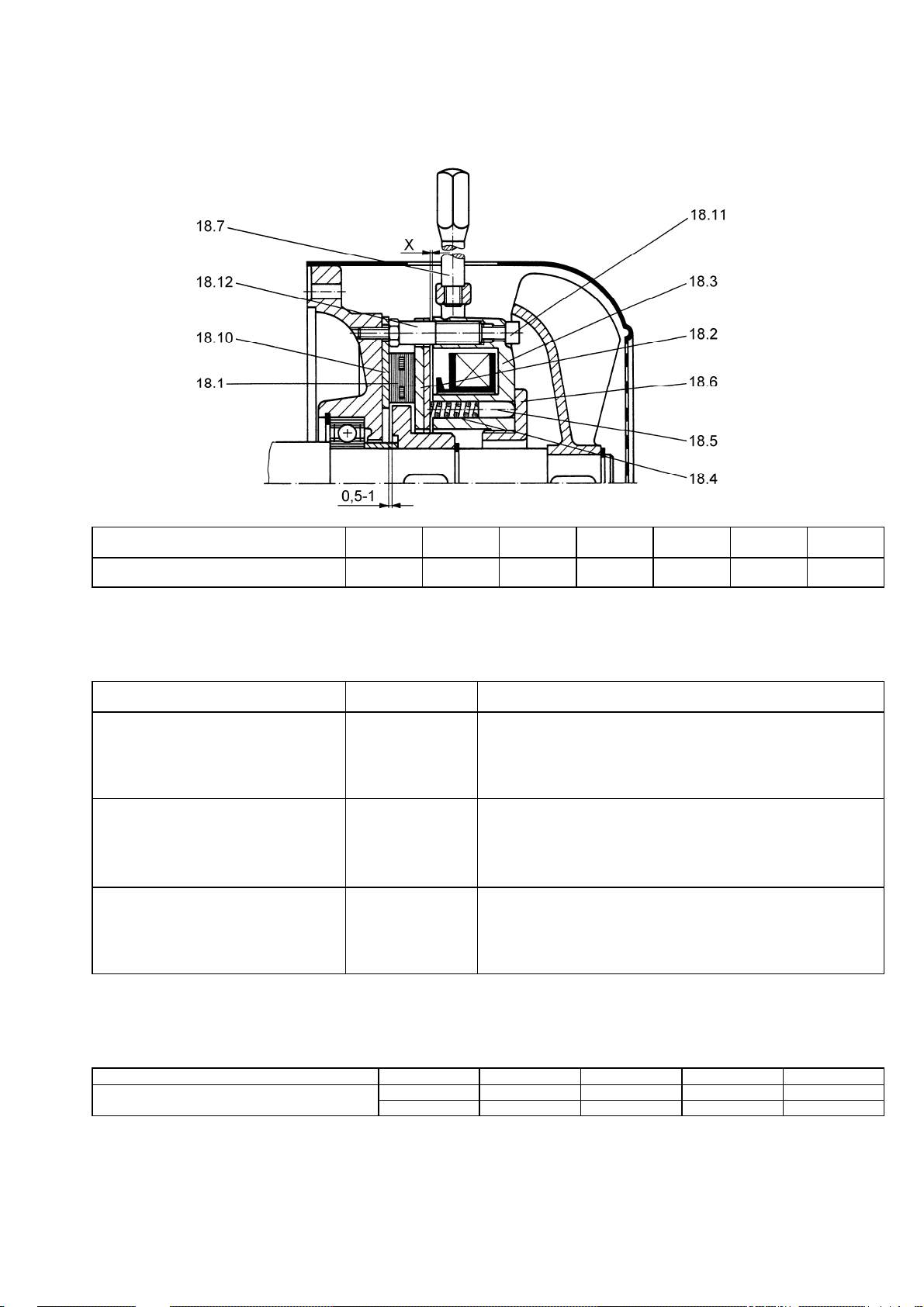
Deutsch / English
Bild 1: Einscheiben-Federkraftbremse
Fig. 1: Single-disc springloaded brake
Bremsmoment / Braking torque
(Nm)
Luftspalt X / Air gap X
(mm)
2
0,2
4
0,2
8
0,2
16
0,2
32
0,3
60
0,3
Bild 2: Schmierstoffe
Fig. 2: Lubricants
Betriebsbedingungen
Operating conditions
Normal
Normal
Hohe Temperaturen,
extreme Betriebsbedingungen
High temperatures,
extreme operating conditions
Tiefe Temperaturen
Low temperatures
Wärmeklasse
Temperature class
F
H
F
Wälzlagerfett / Einsatzbereich
Bearing grease / Application
Baugrößen 56 – 112: Lithiumseifenfett / -30 C bis +140 C
Frame sizes 56 – 112: lithium-based grease / -30 C to +140 C
Hochtemperatur- und Langzeitschmierstoff,
vollsyntetisches Grundöl / -20 C bis +180 C
High-temperature and long-term grease,
fully synthetic base oil / -20 C to +180 C
.
Tieftemperaturschmierstoff,
Barium-Komplex / -50 C bis +150 C
Low-temperature grease,
barium complex / -50 C to +150 C
Bild 3: Anziehdrehmomente für Schraubenverbindungen der Klemmbrettanschlüße
Fig. 3: Tightening torques for the screws and bolts of electrical connections on terminal boards
Gewinde- / Thread-
Anziehdrehmoment / Tightening torque min. 0,8 1,8 2,7 5,5 9,0
(Nm) max. 1,2 2,5 4,0 8,0 13,0
Die Anziehdrehmomente gelten, soweit keine anderen Werte angegeben sind!
The tightening torques apply unless alternative values are specified.
M4 M5 M6 M8 M10
8
80
0,3
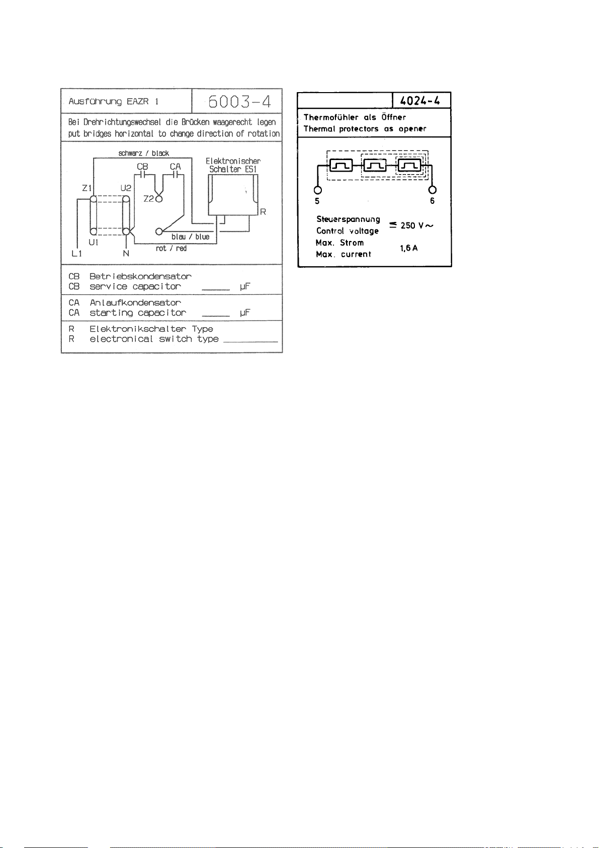
Bild 4: Anschlußschaltbild
Fig. 2: Connection diagram
Deutsch / English
9


KNF worldwide
Find your local KNF partner on: www.knf.com
 Loading...