

KNF LIQUIPORT 100**.18 Series, LIQUIPORT 300**.18 Series, LIQUIPORT 1.100**.18 Series, LIQUIPORT 1.300**.18 Series Operating Instructions Manual

LAB
LIQUIPORT
NF 100_ _.18
NF 1.100_ _.18
NF 300_ _.18
NF 1.300_ _.18
OPERATING INSTRUCTIONS
DIAPHRAGM
LABORATORY PUMP

KNF Flodos AG
Wassermatte 2
6210 Sursee, Switzerland
Tel +41 (0)41 925 00 25
Fax +41 (0)41 925 00 35
www.knf.com

Operating Instructions LIQUIPORT EN Content
1. General information 5
1.1 Information about the instructions 5
1.2 Warnings 6
1.3 Symbols 7
1.4 Disclaimer of liability 8
1.5 Manufacturer's address 8
1.6 Year of manufacture 8
1.7 Other applicable documents 8
1.8 Copyright 8
1.9 Warranty conditions 8
2. Safety 9
2.1 Intended use 9
2.2 Reasonably foreseeable misuse 9
2.3 Owner's responsibility 10
2.4 Personnel requirements 10
2.5 Product-specific dangers 11
2.6 Personal protective equipment 12
2.7 Safety equipment 12
2.8 Environmental protection considerations 13
2.9 Danger areas 13
2.10 Declaration of conformity 14
3. Technical data 15
3.1 Items included in delivery 15
3.2 Storage conditions 15
3.3 Pump materials 15
3.4 Product key 16
3.5 Dimensions 17
3.6 Installation location requirements 18
3.7 Electrical connections and performance data 18
3.8 Other parameters 19
3.9 External actuation (RC version only) 20
3.10 Hydraulic ratings 21
3.11 Hydraulic connections 22
3.12 Transferred medium 23
4. Assembly and function 24
4.1 Metering pump assembly 24
4.2 Operating principle 24
5. Shipment 25
5.1 Checking delivery 25
5.2 Registering a complaint 25
5.3 Arranging for return 25
6. Installation and initial start-up 26
6.1 Safety 26
6.2 Installation 27
6.3 Initial start-up 30
7. Operation 31
7.1 Safety 31
7.2 Operating controls 32
7.3 Starting the pump 32
7.4 Stopping the transferring operation 32
7.5 Adjusting the flow rate 33
8. RC version – external actuation 34
8.1 External actuation analog input 34
8.2 Start/Stop pulse input 35
KNF Flodos | BA_LIQUIPORT_EN_11_153820.docx | Translation of original operating instructions, English 3

Content Operating Instructions LIQUIPORT EN
8.3 Digital output 36
8.4 Shutting down the pump in an emergency 36
9. Cleaning and maintenance 37
9.1 Safety 37
9.2 Maintenance plan 37
9.3 Cleaning the pump 38
9.4 Cleaning / replacing valve plates and pump diaphragm 39
9.5 Checking that pump is leak-tight 42
10. Shutdown 43
10.1 Safety 43
10.2 Procedure 43
11. Troubleshooting 44
11.1 Safety 44
11.2 Rectifying transfer problems 45
12. Spare parts and accessories 46
12.1 Spare parts 46
12.2 Accessories 46
13. Decontamination declaration 47
4 KNF Flodos | BA_LIQUIPORT_EN_11_153820.docx | Translation of original operating instructions, English

Operating Instructions LIQUIPORT EN General information
Contents
Storage location
Passing on
Project pumps
Illustrations in the instructions
1. General information
1.1 Information about the instructions
The Operating Instructions contain important notes on how to use the
pump. In order to ensure safe working and proper functioning it is essential to observe all the specified safety precautions.
These Operating Instructions are part of the product, and must be
stored in its immediate vicinity in a location accessible to personnel at
all times.
These Operating Instructions are part of the product, and must be
passed on to the next owner if the device is resold.
Customer-specific project pumps (pump models which begin with "PL"
or "PML") may differ from the Operating Instructions, in which case the
agreed specification is also applicable. It is listed with the other applicable documents.
Illustrations in these Operating Instructions may be to scale, but do not
have be.
The illustrations may differ slightly from the actual product.
KNF Flodos | BA_LIQUIPORT_EN_11_153820.docx | Translation of original operating instructions, English 5

General information Operating Instructions LIQUIPORT EN
DANGER
Indicates a dangerous situation which will lead directly to death or serious injury if it is not avoided.
WARNING
Indicates a dangerous situation which may lead to death or serious
injury if it is not avoided.
CAUTION
Indicates a dangerous situation which may lead to moderate or minor
injuries if it is not avoided.
NOTE
Indicates a situation which may cause damage to property if it is not
avoided.
1.2 Warnings
Warnings in the Operating Instructions are identified with the danger
symbol, keywords and colours. These provide an indication of the extent of the danger.
6 KNF Flodos | BA_LIQUIPORT_EN_11_153820.docx | Translation of original operating instructions, English

Operating Instructions LIQUIPORT EN General information
WARNING
Danger of injuries and property damage caused by illegible labels
The labelling on the device may become illegible with time.
- Maintain labels on the device in a legible condition.
- Replace any illegible labels.
Recycling
Not to be disposed of with household waste
General danger symbol
Further details of the nature of the danger are provided in the warning highlighted by this symbol.
Electrical danger
Fire danger
Danger of caustic burns or burns
Danger of automatic start-up
Disconnect device from power supply by pulling out the mains plug
1.3 Symbols
The following symbols appear in the Operating Instructions, on labels
on the device, and on its packaging:
The following symbols in the Operating Instructions and on the device
and its packaging indicate environmental protection considerations:
The following symbols in safety precautions and on the device indicate
the nature of the danger:
KNF Flodos | BA_LIQUIPORT_EN_11_153820.docx | Translation of original operating instructions, English 7

General information Operating Instructions LIQUIPORT EN
1.4 Disclaimer of liability
In preparing the contents of these Operating Instructions, account has
been taken of applicable regulations and the state of the art.
The manufacturer can accept no liability for any damage or malfunctions caused by failure to follow the Operating Instructions.
The manufacturer can accept no liability for any damage or malfunctions caused by modification or conversion of the device or improper
handling.
The manufacturer can accept no liability for any damage or malfunctions caused by the use of non-approved spare parts and accessories.
1.5 Manufacturer's address
KNF Flodos AG
Wassermatte 2
6210 Sursee, Switzerland
Tel +41 (0)41 925 00 25
Fax +41 (0)41 925 00 35
www.knf.com
1.6 Year of manufacture
The year of manufacture is shown on the device's type plate.
1.7 Other applicable documents
The documents listed must also be taken into consideration.
▪ Chemical resistance list
▪ Sales documents
▪ GTCs
1.8 Copyright
The information, texts and illustrations in these Operating Instructions
are protected by copyright. The contents of these Operating Instructions must not be copied, translated or passed to third parties without
the written consent of the manufacturer.
1.9 Warranty conditions
The applicable warranty conditions are set out in the General Terms
and Conditions of Business and the sales documents.
The warranty does not cover the following:
▪ Malfunctions caused by particles/fibres in the valve system
▪ Sticking of the valve system as a result of inadequate flushing
8 KNF Flodos | BA_LIQUIPORT_EN_11_153820.docx | Translation of original operating instructions, English

Operating Instructions LIQUIPORT EN Safety
2. Safety
2.1 Intended use
This pump is intended exclusively for use as follows:
▪ For transferring and metering liquids.
▪ For indoor operation.
▪ For temporary operation in laboratories for research pur-
poses.
▪ For operation in accordance with the operating parameters
specified in the technical data (see Chapter 3) and other applicable documents.
▪ For transferring media which meet the requirements in the
technical data and other applicable documents.
▪ For operation in fully assembled condition.
▪ For upright operation on a firm table top.
2.2 Reasonably foreseeable misuse
The pump may not:
▪ be operated in an explosive atmosphere;
▪ be used to transfer explosive media;
▪ be used to produce foodstuffs or pharmacological products
(additional certifications are required for this purpose);
▪ be used to transfer media whose compatibility with the pump
head, valves, diaphragm and seals has not been established;
KNF Flodos | BA_LIQUIPORT_EN_11_153820.docx | Translation of original operating instructions, English 9

Safety Operating Instructions LIQUIPORT EN
WARNING
Danger of injuries and property damage caused by insufficiently
qualified staff
Improper use of the pump may result in serious injury and damage to
property.
- All activities must be performed only by adequately qualified
personnel.
Trained personnel
Specialist personnel
Unauthorised personnel
2.3 Owner's responsibility
The operator is responsible for compliance with the safety precautions
in these Operating Instructions and with any safety, accident prevention and environmental protection regulations which apply to the medium to be transferred and the range of applications of the device.
These include the following in particular:
▪ The operator must perform a risk assessment to identify any
additional risks which may arise from the specific working conditions at the pump's installation location and the nature of the
medium to be transferred. The operator must convert these
into instructions for operating the device.
▪ The operator must ensure that any employees working with
the pump have read the Operating Instructions.
▪ The operator must train personnel at regular intervals and in-
form them of the risks involved.
▪ The operator must provide personnel with the necessary pro-
tective equipment as specified in the safety data sheet for the
medium to be transferred.
▪ The operator must maintain the pump in perfect working or-
der.
▪ The operator must ensure compliance with the maintenance
intervals described in the Operating Instructions.
2.4 Personnel requirements
The following qualifications are specified for various activities in the
Operating Instructions:
These have been instructed in the task assigned to them and made
aware of potential dangers and risks. This training is the minimum
qualification for working on the device. Where no other qualification is
specified, the activity must be performed by a trained individual as a
minimum.
The specialist training, knowledge and experience of such personnel,
together with their knowledge of the relevant regulations, standards
and directives, allow them to perform their assigned duties correctly,
and to independently identify and avoid potential dangers and risks.
Individuals whose reactions have been impaired by the consumption
of medicines, alcohol, drugs or by other causes and conditions are not
authorised to perform activities on the device.
10 KNF Flodos | BA_LIQUIPORT_EN_11_153820.docx | Translation of original operating instructions, English
Operating Instructions LIQUIPORT EN Safety
DANGER
Danger of injuries and property damage caused by leaks in connections and the pump head
Poisoning and caustic burns, or undesirable reactions caused by escaping hazardous materials
- Maintain the torque of connections (see hydraulic connec-
tions)
- Check tightening torque of head screws regularly
- Only use pump if it is in perfect working order
- Operate pump in accordance with the technical data
DANGER
Danger of injuries and property damage caused by medium escaping from the discharge outlet
Poisoning and caustic burns, or undesirable reactions caused by escaping hazardous materials
- Place the pump in a suitable collecting vessel
- Never close the discharge outlet
- If medium escapes from the pump's discharge outlet, stop
using the pump and contact your KNF dealer
DANGER
Risk of fire from escaping flammable media
Escaping or leaking flammable media can produce a combustible environment.
- Take fire protection precautions that are appropriate for the
transferred media
- Keep ignition sources away
- Keep suitable extinguishers accessible
- Use means of fire detection
WARNING
Danger of serious injuries or property damage caused by escaping media in the event of overpressure on the suction side
Excessive pressure on the suction side will result in uncontrolled escape of fluid, even if the pump is not operating
- Avoid overpressure on the suction side
2.5 Product-specific dangers
This chapter describes residual risks that have been identified in a risk
assessment. Safety precautions and warnings in this chapter and in
other chapters in the Operating Instructions must be observed in order
to avoid dangerous situations.
KNF Flodos | BA_LIQUIPORT_EN_11_153820.docx | Translation of original operating instructions, English 11

Safety Operating Instructions LIQUIPORT EN
Safety gloves
to protect skin from contact with the transferred medium in accordance with the safety data sheet.
Safety glasses
to protect the eyes from contact with the transferred medium in accordance with the safety data sheet.
Face protection
to protect skin and eyes from contact with the transferred medium in
accordance with the safety data sheet.
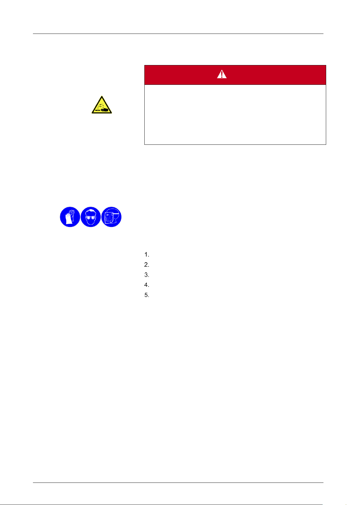
DANGER
Danger of injuries and property damage caused by medium escaping from the discharge outlet
Poisoning and caustic burns, or undesirable reactions caused by escaping hazardous materials
- Place the pump in a suitable collecting vessel
- Check the discharge outlet regularly for leaks
- Never close the discharge outlet (see Fig. 1)
- If medium escapes from the pump's discharge outlet, stop
using the pump and contact your KNF dealer
Fig. 1: Discharge outlet
2.6 Personal protective equipment
Special protective equipment must be used when performing certain
tasks. These are indicated separately in the individual chapters.
Where the wearing of protective equipment is concerned it is essential
to observe the safety data sheet for the medium to be transferred.
The following symbols appear in the working area or in the Operating
Instructions:
2.7 Safety equipment
2.7.1 Discharge outlet
If the pump diaphragm ruptures, the transferred medium is channelled
out of the pump through the discharge outlet (see Fig. 1).
2.7.2 Emergency Stop
Pulling out the mains plug acts as an Emergency Stop. If the pump is
installed permanently, an Emergency Stop and a maintenance switch
must be fitted.
12 KNF Flodos | BA_LIQUIPORT_EN_11_153820.docx | Translation of original operating instructions, English

Operating Instructions LIQUIPORT EN Safety
2.8 Environmental protection considerations
All replacement parts should be properly stored and disposed of in accordance with the applicable environmental protection regulations. Ensure adherence to the pertinent national and international regulations.
This applies especially to parts contaminated with toxic substances.
Dispose of any packaging material that is no longer required in an environmentally friendly manner. The packaging materials are recyclable.
Dispose of end-of-life equipment in an environmentally friendly manner. Use appropriate waste collection systems for the disposal of endof-life equipment. Used pumps contain valuable recyclable materials.
2.9 Danger areas
A discharge of aggressive, corrosive, ionizing, flammable or biological
liquids can be dangerous.
The pump danger area should be limited by safe workplaces. Safe
workplaces should comply with the requirements of local work safety
regulations.
KNF Flodos | BA_LIQUIPORT_EN_11_153820.docx | Translation of original operating instructions, English 13

Safety Operating Instructions LIQUIPORT EN
2.10 Declaration of conformity
14 KNF Flodos | BA_LIQUIPORT_EN_11_153820.docx | Translation of original operating instructions, English
Operating Instructions LIQUIPORT EN Technical data
Assembly
Material1)
Pump head
PP
Valve plate / seals
FFKM
Diaphragm
PTFE-coated
Housing
PA, TPE, PC
Assembly
Material1)
Pump head
PVDF
Valve plate / seals
FFKM
Diaphragm
PTFE-coated
Housing
PA, TPE, PC
Assembly
Material1)
Pump head
PTFE
Valve plate / seals
FFKM
Diaphragm
PTFE-coated
Housing
PA, TPE, PC
3. Technical data
3.1 Items included in delivery
▪ LIQUIPORT pump
▪ Mains plug
▪ Operating instructions
3.2 Storage conditions
▪ Pumps must be stored in a dry place and protected from con-
tamination.
▪ The storage temperature must be between 5°C and 40°C.
▪ The pump is supplied with protective caps. These protective
caps must be fitted during storage.
▪ Store pump upright and with protection.
3.3 Pump materials
The type designation KT stands for:
Tab. 1: KT
1)
according to DIN ISO 1629 and 1043.1
The type designation TT stands for:
Tab. 2: TT
1)
according to DIN ISO 1629 and 1043.1
The type designation FT stands for:
Tab. 3: FT
1)
according to DIN ISO 1629 and 1043.1
KNF Flodos | BA_LIQUIPORT_EN_11_153820.docx | Translation of original operating instructions, English 15

Technical data Operating Instructions LIQUIPORT EN
Description
Meaning
PML / PL
Customer-specific designs
NF
Flodos liquid pump
100 / 1.100 / 300 / 1.300
Pump type
KT / TT / FT
Head material
.18
Laboratory device with housing
S / RC
S without external actua-
tion
RC with external actuation
(remote control)
NF 100 KT .18 S
.18
100 / 1.100 / 300 / 1.300
NF
S / RC
- / PMLxxxx / PLxxxx
3.4 Product key
Tab. 4: Product key
16 KNF Flodos | BA_LIQUIPORT_EN_11_153820.docx | Translation of original operating instructions, English

Operating Instructions LIQUIPORT EN Technical data
3.5 Dimensions
Fig. 2: Mounting dimensions LIQUIPORT 100 / LIQUIPORT 1.100
Fig. 3: Mounting dimensions LIQUIPORT 300 / LIQUIPORT 1.300
KNF Flodos | BA_LIQUIPORT_EN_11_153820.docx | Translation of original operating instructions, English 17

Technical data Operating Instructions LIQUIPORT EN
NOTE
An unsuitable location may cause damage to the device
- Install in a dry place
- Protect the installation location of the pump from water in
the form of rain, spray, splashes and drips
- Do not operate the pump in an aggressive or flammable en-
vironment
- Choose a safe location (a level, flat surface) for the pump
- Place the pump in a suitable collecting pan
- If the stability of the pump cannot be ensured, fasten the
pump in place using two screws
- Make sure that the hose connections can be fitted without
strain on the hoses
- Protect the pump against shocks, impacts and strong vibra-
tions
Pump type
LIQUIPORT
100
LIQUIPORT
1.100
Nominal mains voltage [V]
100 – 240V AC +/- 10%,
Frequency [Hz]
50-60 Hz
Max. power consumption AC
100 V / 115 V / 240 V [W]
12 / 12 / 12
15 / 15 / 16
Max. power consumption DC [W]
12
15
Pump DC voltage [V]
24V DC
Maximum operating current, DC
RMS 24 V [A]
0.5
0.63
Max. short-term peak current [A]
0.8
0.8
Power supply fuse
Electronic overload protection
Pump fuse
Electronic overload protection
Pump type
LIQUIPORT
300
LIQUIPORT
1.300
Nominal mains voltage [V]
100 – 240V AC +/- 10%,
Frequency [Hz]
50-60 Hz
Max. power consumption AC
100 V / 115 V / 240 V [W]
22 / 22 / 24
30 / 30 / 32
Max. power consumption DC [W]
22
29
Pump DC voltage [V]
24V DC
Maximum operating current, DC
RMS 24 V [A]
0.92
1.2
Max. short-term peak current [A]
1.3
1.3
Power supply fuse
Electronic overload protection
Pump fuse
Electronic overload protection
3.6 Installation location requirements
The pump is designed to be operated in an upright position.
3.7 Electrical connections and performance data
Tab. 5: Electrical data LIQUIPORT 100
Tab. 6: Electrical data LIQUIPORT 300
18 KNF Flodos | BA_LIQUIPORT_EN_11_153820.docx | Translation of original operating instructions, English

Operating Instructions LIQUIPORT EN Technical data
Pump type
LIQUIPORT 100
LIQUIPORT 1.100
LIQUIPORT 300
LIQUIPORT1.300
Pump weight [kg] 1)
1.0
1.5
Permissible ambient temperature [°C]
+5 to +40
Permissible media temperature
[°C]
+5 to +80
Permissible working height [m
above sea level]
2000
Max. humidity
90% (non-condensing)
Nominal speed [rpm]
3000 rpm
Noise level [dBA]
< 40dBA
Pump protection type
IP 65
Power supply protection type
IP 40
Protection class
III
3.8 Other parameters
Tab. 7: Other parameters
1)
The weight may differ slightly from the stated value, depending on
the version.
KNF Flodos | BA_LIQUIPORT_EN_11_153820.docx | Translation of original operating instructions, English 19

Technical data Operating Instructions LIQUIPORT EN
Parameter
Value
Analog input
Signal range
0-10V
Signal range optional 1)
0-20mA
Input resistance
133 k at 0-10 V
510 at 0-20mA
Dielectric strength
24V DC
Digital input
Signal range
Pull up to 24 V
Dielectric strength
24V DC
Voltage level without external wiring
19V typ.
Level low
≤ 4.0V = low
Level high
≥ 14.0V = high
Pull-up resistance
10 k
Resistance to ground/GND
43 k
Digital output – open-collector output (NPN transistor to GND)
Dielectric strength
24V DC
Loading capacity/output current
low level
0…10mA typ.
20mA max.
1 Analog input
Brown
2 External actuation jumper
White
3 Pulse input
Blue
4 Open collector output
Black
5 Ground
Grey
Pin no.
Lead colour
Description
Function
1
brown
Analog input
(0%) 15% to 100% flow
rate
2
white
External actuation
jumper
Switches pump over to
external actuation.
→ Control knob is deactivated
3
blue
Pulse input
Start/Stop via external
actuation
4
black
Open collector output
Operating mode output
(On/Off)
5
grey
Ground/GND
--
3.9 External actuation (RC version only)
Tab. 8: External actuation
1)
Optional on request.
Fig. 4: RC cable pin assignment
Tab. 9: RC cable pin assignment
20 KNF Flodos | BA_LIQUIPORT_EN_11_153820.docx | Translation of original operating instructions, English

Operating Instructions LIQUIPORT EN Technical data
Type
LIQUIPORT 100
LIQUIPORT 1.100
Flow rate [l/min]
1) 2)
0.2 – 1.3
0.2 - 1.3
Suction head [mWG]
3
3
Max. inlet pressure [bar g] 3)
0.4
0.4
Permissible pressure [bar g]
1.0
6.0
Permissible medium viscosity
[cSt]
150
150
3.10 Hydraulic ratings
Tab. 10: Hydraulic ratings LIQUIPORT 100 / LIQUIPORT 1.100
Fig. 5: Flow rate curve LIQUIPORT 100
Fig. 6: Flow rate curve LIQUIPORT 1.100
1)
Measured with water at 20°C
2)
Flow rates may vary from the values shown, depending on fluid vis-
cosity, pump head material and the hoses / hose connectors used.
3)
Overpressure on the suction side will result in uncontrolled escape of
fluid, even if the pump is not operating. The pressure increase via the
pump must be positive.
KNF Flodos | BA_LIQUIPORT_EN_11_153820.docx | Translation of original operating instructions, English 21

Technical data Operating Instructions LIQUIPORT EN
Pump type
LIQUIPORT 300
LIQUIPORT 1.300
Flow rate [l/min]
1) 2)
0.5 – 3.0
0.5 – 3.0
Suction head [mWG]
3 3 Max. inlet pressure [bar g] 3)
0.4
0.4
Permissible pressure [bar g]
1.0
6.0
Permissible medium viscosity
[cSt]
150
150
Pump type
Connection
LIQUIPORT 100
LIQUIPORT 1.100
Internal thread NPT 1/8" with hose connector for hose ID 8mm
LIQUIPORT 300
LIQUIPORT 1.300
Internal thread NPT 3/8" with hose connector for hose ID 12mm
Tab. 11: Hydraulic ratings
Fig. 7: Flow rate curve LIQUIPORT 300
Fig. 8: Flow rate curve LIQUIPORT 1.300
1)
Measured with water at 20°C
2)
Flow rates may vary from the values shown, depending on fluid vis-
cosity, pump head material and the hoses / hose connectors used.
3)
Overpressure on the suction side will result in uncontrolled escape of
fluid, even if the pump is not operating. The pressure increase via the
pump must be positive.
3.11 Hydraulic connections
22 KNF Flodos | BA_LIQUIPORT_EN_11_153820.docx | Translation of original operating instructions, English
Tab. 12: Hydraulic connections

Operating Instructions LIQUIPORT EN Technical data
Parameter
Value
Permissible medium viscosity [cSt]
150
Ideally free of solids, max. particle size [µm]
< 70
Permissible media temperature1 [°C]
+5 to +80
WARNING
Poisoning and caustic burns
If corrosive, poisonous, ionising or biological media come into contact
with skin, eyes and the respiratory tract they may cause serious injuries
- Observe the safety data sheets for the media to be trans-
ferred
- Use personal protective equipment
- Operate the pump in a suitably protected area
- Check the resistance of any parts which come into contact
with the fluid (see chemical resistance list or consult your local
KNF dealer)
WARNING
Damage caused by ionising radiation
Radioactive materials cause serious damage to health and reduce the
service life of the pump.
- Decontaminate the pump
- Wear personal protective equipment
- Mark the pump
NOTE
If the absence of solid material in the pumped material is not ensured, a filter < 70 µm with a sufficiently large filtration surface area
must be installed upstream of the pump in order to prevent damage
to the pump.
NOTE
Before using a medium, check the compatibility of the materials of
the pump head, pump housing, diaphragm and valves with the medium.
- Check the resistance, see the resistance list
- Clarify resistance with KNF
3.12 Transferred medium
KNF Flodos | BA_LIQUIPORT_EN_11_153820.docx | Translation of original operating instructions, English 23
1
Applies to water and low-reactivity media. For aggressive media, re-
sistance is to be checked at a higher medium temperature.

Assembly and function Operating Instructions LIQUIPORT EN
1 On/Off button
2 Control knob
3 Flow rate indicator
4 Standby indicator
5 External indicator
6 Inlet
7 Pump head
8 Outlet
9 Power supply plug
10 External actuation plug (RC
version only)
1 Outlet valve
2 Inlet valve
3 Working chamber
4 Diaphragm
5 Eccentric
6 Connecting rod
7 Pump drive
4. Assembly and function
4.1 Metering pump assembly
Fig. 9: Diaphragm pump
4.2 Operating principle
Fig. 10: Pump assembly
The diaphragm liquid pumps are based on reciprocating displacement
pump technology. The elastic diaphragm (4) is moved up and down by
the eccentric (5) and the connecting rod (6). In the downward stroke it
aspirates the medium to be transferred via the inlet valve (2). In the
upward stroke the diaphragm pushes the medium out of the pump
head via the outlet valve (1). The diaphragm hermetically seals off the
working chamber (3) from the pump drive (7).
24 KNF Flodos | BA_LIQUIPORT_EN_11_153820.docx | Translation of original operating instructions, English

Operating Instructions LIQUIPORT EN Shipment
DANGER
Danger of poisoning, chemical burns, or radioactive contamination through contact with pump parts that are not decontaminated
Contact with pump parts that are not properly decontaminated will result in poisoning, chemical burns, or radioactive contamination.
- Use personal protective equipment
- Flush and decontaminate the pump until the possibility of
danger can be eliminated.
- Label any pumps that are used with particularly dangerous
media
- Only decontaminated pumps may be sent
Requirements
Procedure
Requirements
Procedure
Requirements
Procedure
5. Shipment
5.1 Checking delivery
▪ Device delivered and packaged
Check delivery for visible damage
Check that delivery is correct and complete using the packing list
In the event of a discrepancy, register a complaint.
Keep original packaging in case you have to return the item
5.2 Registering a complaint
▪ Device damaged or incomplete
If there are any visible signs of damage, only accept the delivery
with reservations.
Damage and complaints of any kind should be recorded on the
delivery note
Notify the manufacturer of any damage and complaints
5.3 Arranging for return
▪ Device damaged or incomplete
Contact KNF before returning the device
Flush and decontaminate pump
Fill out decontamination declaration and attach to the pump
Send the pump in its original packaging to a service location or
one of our product centres
The pump can be sent by parcel service or post in its original
packaging
KNF Flodos | BA_LIQUIPORT_EN_11_153820.docx | Translation of original operating instructions, English 25
Installation and initial start-up Operating Instructions LIQUIPORT EN
NOTE
KNF retains the right to refuse repair of pumps that are used to move
hazardous materials.
This applies particularly to the following materials:
- Poisons
- Radioactive media
- Elementary halogens (e.g. bromine)
WARNING
Danger as a result of incorrect installation
Injuries or damage to equipment caused by escaping media
- Follow installation instructions
- After assembly, test the system with a harmless liquid
- Only use pump if it is in perfect working order
WARNING
Danger of serious injuries or property damage caused by escaping media in the event of rupturing of the pump diaphragm
Poisoning and caustic burns caused by escaping media as a result of
rupturing of the pump diaphragm. If the pump diaphragm ruptures, the
medium is channelled out of the pump through the discharge outlet.
- When transferring critical media, operate the pump in a col-
lecting tank
- Check discharge outlet for leaks
WARNING
Danger of serious injuries or property damage caused by escaping media in the event of overpressure on the suction side
Overpressure on the suction side will result in uncontrolled escape of
fluid, even if the pump is not operating.
- Avoid overpressure on the suction side
Requirements
Personnel
Personal protective equipment
6. Installation and initial start-up
6.1 Safety
The following requirements apply to all the activities described in this
chapter:
▪ Device is in perfect working order
▪ The system is operated with water
▪ Must be assembled by specialist personnel
▪ Not required
26 KNF Flodos | BA_LIQUIPORT_EN_11_153820.docx | Translation of original operating instructions, English
Operating Instructions LIQUIPORT EN Installation and initial start-up
NOTE
For problem-free, safe operation the following instructions should be
followed:
- Install in a dry place.
- Protect the installation location of the pump from water in the
form of rain, spray, splashes and drips.
- Do not operate the pump in an aggressive or flammable envi-
ronment.
- Choose a safe location (a level, flat surface) for the pump.
- If the stability of the pump cannot be ensured, fasten the
pump in place using two screws.
- Make sure that the hose connections can be fitted without
strain on the hoses.
- Protect the pump against shocks, impacts and strong vibra-
tions.
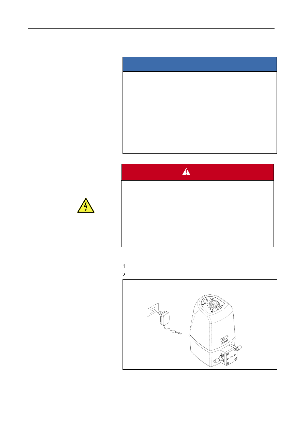
DANGER
Risk of electric shock
- Only operate the pump with the power supply unit supplied.
- Connect the cable from the mains plug to the pump's power
supply socket.
- Plug the mains plug into a correctly installed and properly
earthed mains socket.
- Ensure that the mains plug is protected from water splashes.
- Do not open pump housing or power supply unit.
- Disconnect pump from power supply during maintenance
work.
- If pump is installed permanently, fit a maintenance switch.
6.2 Installation
Before installation, store the pump at the installation location to bring it
up to ambient temperature.
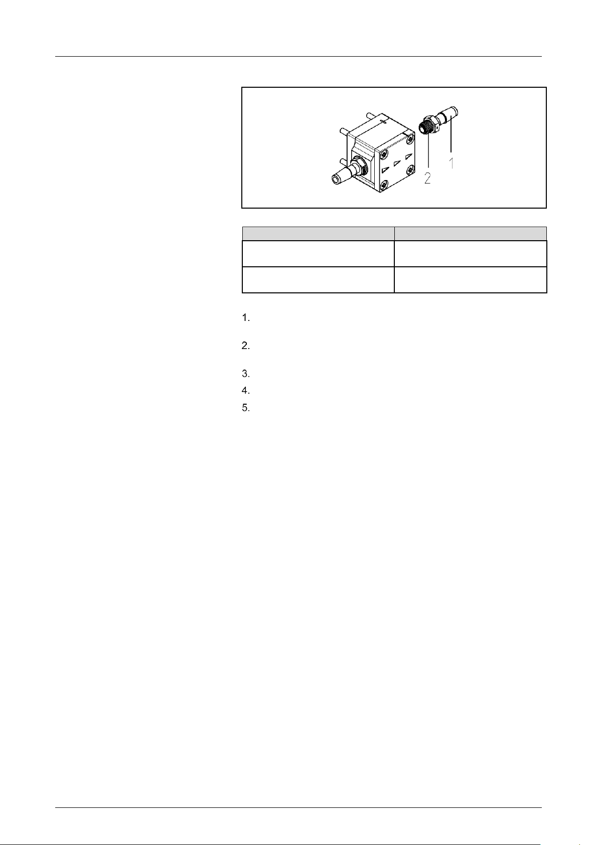
6.2.1 Connect mains plug
When connecting the device to a power source, the relevant norms, directives, regulations and technical standards must be observed.
Use suitable adapters in the power supply unit
Connect power supply unit to pump
KNF Flodos | BA_LIQUIPORT_EN_11_153820.docx | Translation of original operating instructions, English 27
Fig. 11: Electrical connection

Installation and initial start-up Operating Instructions LIQUIPORT EN
NOTE
Arrows on the pump head indicate the flow direction.
1 Hose
2 Connector
3 Hose clip
Connected
components
Hoses
Customer-specific
pumps (PL, PML)
6.2.2 Connect hydraulics
Only connect components to the pump that are designed to han-
dle the hydraulic data of the pump (see Chapter 3).
Only use hoses that are suitable for the maximum operating pres-
sure of the pump (see Section 3).
Only use hoses that are sufficiently chemically resistant to the liq-
uids being transferred.
The connections described below apply to standard products. Dif-
ferent connections may apply for customer-specific projects (PML
or PL).
Use of hose connectors
Fig. 12: Hose connector ID 8mm or ID 12mm
Remove protective caps from connections.
Suction and pressure lines (LIQUIPORT 100 and LIQUIPORT
1.100: hose ID 8mm; LIQUIPORT 300 and LIQUIPORT 1.300:
hose ID 12mm), cut off straight with a sharp knife.
Push the hoses onto the connectors as far as they will go.
For pressure applications with LIQUIPORT 1.100 or LIQUIPORT
1.300, secure hoses with suitable hose clips.
Check that the hoses and transition joints (hose connector/hose)
are fitted correctly and securely.
Check that the system is leak-tight.
28 KNF Flodos | BA_LIQUIPORT_EN_11_153820.docx | Translation of original operating instructions, English
Operating Instructions LIQUIPORT EN Installation and initial start-up
1 Connector
2 Teflon sealing tape
Pump type
Internal thread
LIQUIPORT 100
LIQUIPORT 1.100
NPT 1/8"
LIQUIPORT 300
LIQUIPORT 1.300
NPT 3/8"
Use of internal threads
Fig. 13: Internal thread NPT 1/8"
Tab. 13: Internal thread
Remove protective cap and screwed-in connectors from the con-
nections.
Prepare required fitting with corresponding external thread with
suitable sealant (e.g. Teflon sealing tape).
Screw in fitting and tighten.
Check that the fitting is fitted correctly and securely.
Check that the system is leak-tight.
KNF Flodos | BA_LIQUIPORT_EN_11_153820.docx | Translation of original operating instructions, English 29

Installation and initial start-up Operating Instructions LIQUIPORT EN
CAUTION
Danger of rupture of the fluid system as a consequence of overpressure
The pump builds up pressure. In a closed system the max. permitted
operating pressure may be exceeded, thus causing damage to the
pump and/or the system
- In the case of parts that are in contact with the fluid, use only
those that are designed for the pump's operating pressure as
a minimum
- Do not transfer media against shut-off elements or closed sys-
tems, otherwise
- install pressure relief/safety valve and set to 6 bar (in the KNF
product range)
CAUTION
Danger of unexpected chemical reactions with water
Water residues left in the pump from testing in the factory may react
with the transferred medium.
- Before putting the pump into service, flush it with a non-criti-
cal medium
Prerequisites for start-up
▪ All hoses attached properly
▪ Specifications of the power supply must correspond with the
data on the pump and mains plug type plates.
▪ The pump outlet must be clear of any obstruction.
▪ All cables properly connected
6.3 Initial start-up
Before switching on the pump, check the following points:
Tab. 14: Prerequisites for start-up
Only operate the pump under the operating parameters and condi-
tions described in Section 3.
Ensure that the pump is used as intended
(see Section 2.1).
Avoid improper use of the pump
(see Section 2.2).
Observe safety precautions.
6.3.1 Test the system
In order to prevent damage, the safety, leak-tightness and functioning
of the test set-up should be checked using a suitable harmless medium, such as water.
30 KNF Flodos | BA_LIQUIPORT_EN_11_153820.docx | Translation of original operating instructions, English
Operating Instructions LIQUIPORT EN Operation
DANGER
Danger of injuries and property damage caused by hazardous
materials
Poisoning and caustic burns, or undesirable reactions caused by escaping hazardous materials
- Observe the safety data sheets for the media to be trans-
ferred
- Determine the resistance of the head materials
- Check tightening torque of head screws regularly (see Sec-
tion 9.4)
- Check that pump and system are leak-tight
- Maintain the pump regularly
- Only use pump if it is in perfect working order
- Operate pump in accordance with the technical data
WARNING
Danger of undetected diaphragm rupture
The diaphragm may be damaged by aggressive media, and the medium may escape from the discharge outlet
- Operate the pump in a collecting pan
- Flush pump thoroughly after use or if it is not to be used for
an extended period (see Chapter 9)
- Check the discharge outlet regularly for leaks
- Observe the service life of the diaphragm and other elasto-
mer parts (see Maintenance)
WARNING
Danger of splashing media
If corrosive, poisonous, ionising or biological media come into contact
with skin, eyes and the respiratory tract they may cause serious injuries
- Observe the safety data sheets for the media to be trans-
ferred
- Check that the system is leak-tight before use
- Use personal protective equipment
7. Operation
7.1 Safety
KNF Flodos | BA_LIQUIPORT_EN_11_153820.docx | Translation of original operating instructions, English 31

Operation Operating Instructions LIQUIPORT EN
1 On/Off button
2 Control knob
3 Flow rate indicator
4 Standby indicator
5 External indicator
An externally actuated pump will start as soon as a valid control
signal is present.
(see Chapter 8).
Requirements
Personnel
Personal protective equipment
Special tools required
Fig. 15: Starting / stopping the
pump
The following requirements apply to all the activities described in this
chapter:
▪ Device is in perfect working order.
▪ The system has previously been operated and tested with a
suitable harmless medium (e.g. water).
▪ Trained personnel
▪ The type of protective equipment required will depend on the
medium to be transferred.
▪ Observe safety data sheets and regulations for the handling
of the media to be transferred.
▪ At medium temperatures of over 50°C, take safety precau-
tions against burns.
▪ When transferring very aggressive, biological, flammable or
ionising media, a suitable work station with a safety and extraction system is to be used.
7.2 Operating controls
Fig. 14: Operating controls
7.3 Starting the pump
When it is connected to the power supply, the pump is in standby
mode by default, and the "Standby" indicator illuminates.
➔ Briefly press the “On/Off” button and the pump will start to trans-
fer.
The "Standby" indicator goes off.
7.4 Stopping the transferring operation
➔ Briefly press the “On/Off” button and the pump will stop.
The "Standby" indicator goes on.
32 KNF Flodos | BA_LIQUIPORT_EN_11_153820.docx | Translation of original operating instructions, English

Operating Instructions LIQUIPORT EN Operation
Type
Flow rate [l/min]
LIQUIPORT 100
0.2 to 1.3
LIQUIPORT 1.100
0.2 to 1.3
LIQUIPORT 300
0.5 to 3.0
LIQUIPORT 1.300
0.5 to 3.0
If the analog input is active, the "EXT" indicator illuminates and the
control knob has no function. The flow rate is then specified by the
analog input. See Chapter 8.1
The flow rate of the pump is reduced by counterpressure, suction
head and higher medium viscosity.
In the event of counterpressure, the pump will not start at low flow
rate settings.
Reduce counterpressure or select a higher setting.
Fig. 16: Adjusting the flow rate
Operation in the event of counter-
pressure
7.5 Adjusting the flow rate
Set the pump to the required flow rate using the control knob.
The flow rate setting is shown by the flow rate indicator around the
control knob.
Tab. 15: Specified flow
In the event of counterpressure the pump cannot be set to the lower
flow rates. The counterpressure must be reduced or a higher flow rate
must be selected.
Fig. 17: Operating range
KNF Flodos | BA_LIQUIPORT_EN_11_153820.docx | Translation of original operating instructions, English 33

RC version – external actuation Operating Instructions LIQUIPORT EN
WARNING
Danger of automatic start-up
The pump starts up by itself and without warning.
- Send the start command only when the system has been
tested and is ready for operation
- Mark remote-controlled pumps
- Before start-up, check that hoses and equipment are leak-
tight and working properly
- Do not operate the pump with hazardous media
External actuation functions are available only in the RC version.
When the analog input is active, the pump can be started only if a
valid analog signal is present.
The control knob is deactivated. Manual flow rate entry is blocked.
Name
Voltage range
0 – 10V
On threshold
≥ 0.2V
Off threshold
≤ 0.2V
Activating the analog input
1 Brown (analog input)
2 White (external jumper)
3 Blue
4 Black
5 Grey (ground)
6 Jumper
7 Analog signal 0-10V
Fig. 18: RC cable jumper
Fig. 19: "EXT" indicator
8. RC version – external actuation
Connection details and technical data are provided in Chapter 3.9
8.1 External actuation analog input
The analog input can be used to externally control a pump flow rate
from (0%) 15% to 100%.
The analog input must be activated by connecting the RC cable.
➔ With the RC cable connect the white lead (jumper) to the grey
lead (ground) or with the RC connector, connect pin 2 to pin 5.
See Fig. 18
➔ If external actuation is switched on, this is indicated on the pump
by the illuminated "EXT" symbol.
See Fig. 19
Control signals
Tab. 16: Analog input signals
34 KNF Flodos | BA_LIQUIPORT_EN_11_153820.docx | Translation of original operating instructions, English

Operating Instructions LIQUIPORT EN RC version – external actuation
Input
Meaning
Signal
Pulse
Start/Stop on signal pulse
Falling edge below
4.0V
Pulse duration
Maximum pulse duration
200 ms
Activation
time
Minimum delay between activation pulse and deactivation
pulse
300 ms
Deactivation
time
Minimum delay between deactivation pulse and activation
pulse
400 ms
Following a pulse, there must be a delay before a new pulse is
sent. See Tab 17.
The pulse duration must not be longer than 200 ms.
The use of debounced switches is recommended.
1 Brown
2 White
3 Blue (pulse input)
4 Black
5 Grey (ground)
6 Pulse switch
Fig. 21: Pulse input
Fig. 20: range analog input
8.2 Start/Stop pulse input
The pump can be externally started and stopped via the pulse input.
➔ The falling signal edge at the pulse input triggers the starting or
stopping of the pump.
➔ If analog actuation is also used, a valid analog signal must be pre-
sent.
Control signals
Tab. 17: Signal pulse input
Fig. 22: Start/stop impulse control
KNF Flodos | BA_LIQUIPORT_EN_11_153820.docx | Translation of original operating instructions, English 35

RC version – external actuation Operating Instructions LIQUIPORT EN
The minimum switching times must be taken into consideration
when the foot switch is operated. See Chapter 8.2
The pump can also be switched on or off using the Start/Stop button at any time.
The open collector output is internally connected to the collector of
an NPN transistor (BC817-40) and to the internal 24V feed via a
diode.
A maximum of 24V may be connected to the output.
The maximum current via the open collector must be limited to
10mA.
Fig. 23: Foot switch
1 Brown
2 White
3 Blue
4 Black (digital output)
5 Grey (ground)
6 Open collector
Fig. 24: Digital output
Foot switch
With the RC version, the pulse foot switch (KNF Id. no. 155872) can
be connected to the RC connector as an accessory.
➔ When the foot switch is operated, the pulse signal is shorted to
ground, which switches the pump on.
➔ If it is operated again, the pump is switched off.
8.3 Digital output
The current operating status of the pump can be read out via the digital output.
The open collector is only switched on if the pump is transferring.
8.4 Shutting down the pump in an emergency
In order to shut the pump down in an emergency, pull out the mains
plug. Or shut the pump down using the "Stop" button.
36 KNF Flodos | BA_LIQUIPORT_EN_11_153820.docx | Translation of original operating instructions, English

Operating Instructions LIQUIPORT EN Cleaning and maintenance
DANGER
Danger of injuries caused by hazardous materials
Poisoning and caustic burns caused by contact with aggressive, flammable or radioactive media
- Flush the pump thoroughly (see Section 9.3)
- Decontaminate the pump if necessary
- Observe the safety data sheets for the media to be trans-
ferred
- Wear suitable protective equipment
WARNING
Danger of heat build-up as a result of chemical reactions with the
flushing liquid
Significant heat build-up will damage the diaphragm, O-rings and valve
system, resulting in leaks
- Avoid chemical reactions in the pump
- Observe the safety data sheets for the liquid to be transferred
- Observe the following advice
Component
Servicing interval
Pump
- Regular inspection for external
damage or leaks
Pump head
- Clean if the flow rate decreases,
the pump does not work or no
vacuum is created
- Replace parts if necessary
See Chapter 12
Pump diaphragm
- Replace pump diaphragm if the
pumping capacity decreases or
a leak occurs
- Replace pump diaphragm in the
event of repeated head installation
Filter (accessory)
- Replace if it is dirty
Requirements
Personnel
Personal protective equipment
Spare parts
9. Cleaning and maintenance
9.1 Safety
The following requirements apply to all the activities described in this
chapter:
▪ None
▪ Specialist personnel
▪ The type of protective equipment required will depend on the
medium to be transferred.
▪ Observe the safety data sheets for the media to be trans-
ferred.
Use only genuine parts from KNF for servicing work.
9.2 Maintenance plan
Tab. 18: Servicing schedule
KNF Flodos | BA_LIQUIPORT_EN_11_153820.docx | Translation of original operating instructions, English 37

Cleaning and maintenance Operating Instructions LIQUIPORT EN
IMPORTANT:
To ensure satisfactory start-up when the unit is restarted, it is important to ensure that the pump is free of any crystallising, adhesive or
curing media.
NOTE
Never flush non-polar solvents immediately with water
NOTE
The procedure described in Section 9.3.4 is not a sterilisation
9.3 Cleaning the pump
In order to maintain the service life of the pump, after each use and
before any long periods of inactivity the pump must be flushed through
with neutral media.
9.3.1 Acids
- Flush pump with a suitable neutralising liquid in a circular flow
for 10 minutes
- Then flush with distilled water for 5 minutes
9.3.2 Bases
- Flush pump with a suitable neutralising liquid in a circular flow
for 10 minutes
- Then flush with distilled water for 5 minutes
9.3.3 Organic solvents
- Flush pump with isopropyl alcohol (C3H8O) in a circular flow
for 10 minutes
9.3.4 Biological solution
- Flush pump with 10% hydrogen peroxide in a circular flow for
10 minutes
- Then flush with distilled water for 10 minutes
38 KNF Flodos | BA_LIQUIPORT_EN_11_153820.docx | Translation of original operating instructions, English
Operating Instructions LIQUIPORT EN Cleaning and maintenance
DANGER
Danger from hazardous materials
Poisoning and caustic burns or undesirable reactions caused by escaping hazardous materials as a result of incorrect maintenance/servicing or the transferring of incompatible media.
- Follow the maintenance instructions
- Ensure cleanliness during maintenance
(particles on seal faces cause leaks)
- Check that pump and system are leak-tight after mainte-
nance
WARNING
Danger of poisoning and caustic burns
If they come into contact with skin and eyes, aggressive media cause
poisoning and caustic burns.
- Cleaning the pump according to chapter 9.3
- flashing
- Wear protective equipment, e.g. protective gloves, safety
glasses.
Qty
Tools/materials
1
T20 Torx screwdriver
1
Phillips screwdriver no. 2
1
Spare parts kit (see Chapter 12)
1
Torque screwdriver that can be set to 1.5 Nm.
Requirements
Personnel
Personal protective equipment
Tools and materials
Information on procedure
9.4 Cleaning / replacing valve plates and pump diaphragm
▪ The pump must be switched off and disconnected from mains
▪ The pump must be free of any hazardous substances
▪ The hoses must be disconnected from the pump head
▪ Specialist personnel
▪ The type of protective equipment required will depend on the
medium to be transferred.
▪ Observe the safety data sheets for the media to be trans-
ferred.
Tab. 19: Tools/materials
Always replace valve disks, valve seats and seals at the same time to
maintain a satisfactory flow rate.
KNF Flodos | BA_LIQUIPORT_EN_11_153820.docx | Translation of original operating instructions, English 39

Cleaning and maintenance Operating Instructions LIQUIPORT EN
9.4.1 Dismantling the pump head
Fig. 25: LIQUIPORT100
Fig. 26: LIQUIPORT300
Loosen the four head screws (1) and remove the entire head.
40 KNF Flodos | BA_LIQUIPORT_EN_11_153820.docx | Translation of original operating instructions, English

Operating Instructions LIQUIPORT EN Cleaning and maintenance
9.4.2 Removing the valves and seals
Remove the connecting plate (5) from the intermediate plate (7).
Take the valve plate (6) out of the intermediate plate (7).
Remove the resonating diaphragm (3) from the connecting plate
(5).
Remove the O-ring (4) from the head plate.
Carefully grip the diaphragm (8) and remove by turning anti-clock-
wise. Remove the washers (9) and make sure that no washers 9
fall into the pump housing.
We recommend replacing the diaphragm (8).
9.4.3 Cleaning the parts
Clean the diaphragm (8), O-ring (4), resonating diaphragm (3),
valve plate (6), intermediate plate (7) and connecting plate (5) with
a cloth and then blow off with compressed air.
9.4.4 Installing the diaphragm
Place the same number of washers on the connecting rod (9) as
were there previously. Make sure that no washers (9) fall into the
pump housing.
Screw in the diaphragm (8).
By lightly pressing on the diaphragm push the ridge on the under-
side of the diaphragm into the groove of the housing.
9.4.5 Installing the valve plate
Place the dust-free valve plate(6) into the intermediate plate (7),
making sure it is in the correct position.
9.4.6 Installing the pump head
Insert the resonating diaphragm (3) in the connecting plate (5) and
cover with the head plate (2) fitted with a new O-ring (4).
The positions of the intermediate plate (7), the connecting plate
(5) and the head plate (2) with respect to one another are determined by the arrangement of the visible grooves.
Insert the four head screws (1) into the through holes of the pump
head.
Make sure that the flow direction of the pump head (see direc-
tional arrow on the head plate (2)) is the same as previously.
Place the pump head onto the pump housing and alternately
tighten the four head screws (1). The maximum tightening torque
is 1.5 Nm.
Check that pump and system are leak-tight after maintenance.
KNF Flodos | BA_LIQUIPORT_EN_11_153820.docx | Translation of original operating instructions, English 41
Cleaning and maintenance Operating Instructions LIQUIPORT EN
WARNING
Danger of fluid system bursting due to overpressure.
The pump builds up pressure. In a closed system the max. permitted
operating pressure may be exceeded, thus causing damage to the
pump and/or the system.
- In the case of parts that are in contact with the fluid, use only
those that are designed for the pump's operating pressure
- Do not transfer media against shut-off elements or closed
systems, otherwise
- install pressure relief/safety valve and set to 6 bar (in the
KNF product range)
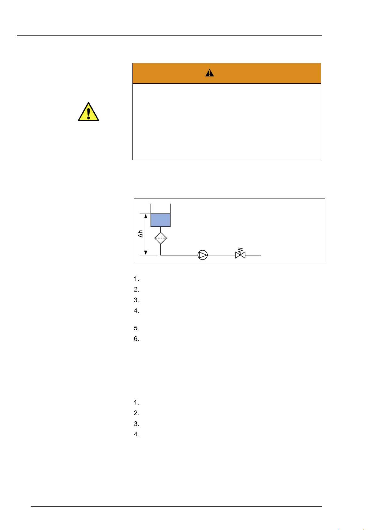
9.5 Checking that pump is leak-tight
In order to ensure correct assembly and hence reliability, it is essential
to perform a leak test.
Fig. 27: Pressure test setup
Set up the system as shown in Fig. 27.
Use distilled water as a test medium.
Set pressure control valve to working pressure.
Make sure that the fitting is leak-tight
(see Section 6.2.2).
Operate pump carefully for 5 minutes.
Check pump for leaks.
If no traces of medium are visible on the head, the pump can be used
in accordance with its specification (see Chapter 3).
Caution!
If it is found that liquid is escaping, under no circumstances should the
pump continue to be used.
Check that connections are leak-tight.
Check tightening torque of head screws.
Check that elastomer parts are clean.
Check leak-tightness again.
If these actions have no effect, contact your local KNF dealer and do
42 KNF Flodos | BA_LIQUIPORT_EN_11_153820.docx | Translation of original operating instructions, English
not under any circumstances continue to use the pump.
Operating Instructions LIQUIPORT EN Shutdown
DANGER
Danger of injuries caused by hazardous materials
Poisoning and caustic burns caused by contact with aggressive, flammable or radioactive media
- Flush the pump thoroughly (see Section 9.3)
- Decontaminate the pump if necessary
- Observe the safety data sheets for the media to be trans-
ferred
- Wear suitable protective equipment
Requirements
Personnel
Personal protective equipment
10. Shutdown
10.1 Safety
The following requirements apply to all the activities described in this
chapter:
▪ System depressurised
▪ Specialist personnel
▪ The type of protective equipment required will depend on the
medium to be transferred.
▪ Observe the safety data sheets for the media to be trans-
ferred.
10.2 Procedure
Flush the whole system including the pump with a neutral liquid
Pump the pump empty (see Section 9.3)
Press the STOP button to end the transferring operation
Unplug the pump from the power supply
Dispose of pump properly
KNF Flodos | BA_LIQUIPORT_EN_11_153820.docx | Translation of original operating instructions, English 43

Troubleshooting Operating Instructions LIQUIPORT EN
Cause
Remedy
Pump not connected to the power
supply.
Connect pump to the power supply.
No voltage in the power supply.
Check room fuse and switch on if necessary.
Connections or hoses are blocked.
Check connections and hoses.
Remove blockage.
External valve is closed or filter is
clogged.
Check external valves and filters.
Worn diaphragm or valve
plates/seals.
Replace diaphragm and valve plates/seals (see Section 9.4).
External actuation connected without a signal
Check external actuation signal.
Pump overload protection has
tripped.
- Flow rate indicator flashing
- Standby indicator not illuminated
Pump unable to build up counterpressure
Pump transferring against pressure that is too high
Reduce pressure in system
Reduce flow rate
Requirements
Personnel
Personal protective equipment
11. Troubleshooting
11.1 Safety
Disconnect the mains plug from the power supply before working on
the pump head.
▪ Pump has been thoroughly flushed/decontaminated
▪ Specialist personnel
▪ None
Pump does not transfer
Tab. 20: Pump does not transfer
1)
Maximum pressure build-up depends on flow rate setting.
Please note: Pump not protected from overpressure.
44 KNF Flodos | BA_LIQUIPORT_EN_11_153820.docx | Translation of original operating instructions, English

Operating Instructions LIQUIPORT EN Troubleshooting
Cause
Remedy
Presence of positive pressure on
the pressure side with simultaneous vacuum or positive pressure
on the suction side.
Change pressure conditions.
Cross-section of hydraulic hoses or
connectors too narrow or restricted.
Disconnect the pump from the system and determine output values.
Remove restriction (e.g. valve) if necessary.
If applicable, use larger-diameter hoses or connectors.
Leaks in connections, hoses or
pump head.
Repair leaks.
Connections or hoses completely
or partially obstructed.
Check connections and hoses.
Remove any parts or particles causing blockages.
Pump head components are
soiled.
Clean head components.
Worn diaphragm or valve
plates/seals.
Replace diaphragm and valve plates/seals (see Chapter 9.4).
Materials chemically damaged by
transferred media.
Select a type of material that is resistant and suitable.
11.2 Rectifying transfer problems
Flow rate, pressure, or vacuum are too low
The pump does not achieve the performance stated in the technical data or on the data sheet.
Tab. 21: Flow rate, pressure, or vacuum are too low
Fault cannot be rectified
If you are unable to identify the cause of the problem, please send the
pump to KNF customer service (see address on last page).
Flush the pump to clear the pump head of any hazardous or ag-
gressive liquids (see Section 9.4).
Dismantle the pump.
Clean the pump (see Section 9.3).
Send the pump, with completed decontamination declaration (see
Chapter 13), to KNF customer service stating the nature of the
transferred medium (see arranging for return).
KNF Flodos | BA_LIQUIPORT_EN_11_153820.docx | Translation of original operating instructions, English 45

Spare parts and accessories Operating Instructions LIQUIPORT EN
Spare parts
Order No.
LIQUIPORT 100 spare parts kit KT head
065262
LIQUIPORT 100 spare parts kit TT head
065262
LIQUIPORT 100 spare parts kit FT head 1)
152631
LIQUIPORT 1.100 spare parts kit KT head
065262
LIQUIPORT 1.100 spare parts kit TT head
065262
LIQUIPORT 1.100 spare parts kit FT head 1)
152631
LIQUIPORT 300 spare parts kit KT head
068691
LIQUIPORT 300 spare parts kit TT head
068691
LIQUIPORT 300 spare parts kit FT head 1)
151902
LIQUIPORT 1.300 spare parts kit KT head
069728
LIQUIPORT 1.300 spare parts kit TT head
069728
LIQUIPORT 1.300 spare parts kit FT head 1)
151903
Connection nipples
Order No.
Spare parts kit screw-in nipples
NPT1/8 ETFE/FFKM
168547
Spare parts kit screw-in nipples
NPT3/8 ETFE/FFKM
168551
Spare parts kit screw-in nipples
NPT1/8 ETFE/EPDM
168555
Spare parts kit screw-in nipples
NPT3/8 ETFE/EPDM
168549
Foot switch
Order No.
LIQUIPORT pulse foot switch
155872
Fasteners
Order No.
Tripod holder
160474
Mounting plate
160473
12. Spare parts and accessories
12.1 Spare parts
Tab. 22: Spare parts
1) The FT head is not compatible with the KT/TT pump housing.
12.2 Accessories
Tab. 23: Connection nipples
Tab. 24: Foot switch
46 KNF Flodos | BA_LIQUIPORT_EN_11_153820.docx | Translation of original operating instructions, English
Tab. 25: Fasteners

Operating Instructions LIQUIPORT EN Decontamination declaration
NOTE
KNF shall only undertake to repair the pump on condition that the
customer provides certification of the transferred media and the
cleaning of the pump (decontamination declaration).
Pump model
Serial no.
Transferred media
Company
Date/Signature
KNF Flodos AG
Wassermatte 2
6210 Sursee, Switzerland
Tel +41 (0)41 925 00 25
Fax +41 (0)41 925 00 35
www.knf.com
13. Decontamination declaration
Copy this page, or print out the decontamination declaration from
our website http://www.knf.com/downloads.
Enter the pump model, the serial no. and the transferred media in
the form below and send the signed form together with the flushed
and cleaned pump to KNF customer service.
Customer decontamination declaration for
repair order
We confirm that the pump below has been used to transfer the following media, and that the pump has been flushed and cleaned.
The pump does not contain aggressive, biological, radioactive, poisonous, or other dangerous media.
KNF Flodos | BA_LIQUIPORT_EN_11_153820.docx | Translation of original operating instructions, English 47

www.knf.com
 Loading...