


LABOPORT®
A
Chemically-resistant Laboratory Pumps
with Modular
ccessories
Operating Instructions
for Laboratory Pumps N810, N820, N840, N842
and for LABOPORT Systems SR..., SH…, SC…, SCC…
Operating Instructions
Vacuum-Controller NC800 / NBC800
KNF 121722-121728 02/10
Translation of original Operating Instructions, english

KNF Neuberger UK Ltd
Ave 2, Station Lane Ind Est,
Witney, Oxfordshire,
OX28 4FA, UK
Tel: +44 (0) 1993 778373
Fax: +44 (0)1993 775148
E-Mail: info@knf.co.uk
www.knf.co.uk

LABOPORT Pumps and Systems Content
Content Page
1.
About this document 4
1.1. Using the Operating Instructions 4
1.2. Symbols and Markings 4
2. Use 5
2.1. Proper Use 5
2.2. Improper Use 5
3. Safety 6
4. System overview 8
5. Technical Data 10
5.1. Pumps 10
5.2. Electrical Supply Unit 17
5.3. Vacuum Controller 17
5.4. Vacuum Systems 18
6. Design and Function 19
6.1. Pump 19
6.2. Separator 20
6.3. High Performance Condenser 21
6.4. Vacuum Controller 22
7. Installation, mounting and
connection 23
7.1. Connect pump 23
7.2. Baseplate 24
7.3. Separator 24
7.4. High Performance Condenser 25
7.5. Electrical Supply Unit and
Vacuum Controller 25
7.6. Gas Ballast 28
7.7. Mounting of Systems 28
7.7.1. System SR 28
7.7.2. System SH 29
7.7.3. System SC 30
7.7.4. System SCC 31
7.7.5. Retrofitting from System SC to
System SCC 32
9.2.3. Emptying and Cleaning the
Separator 37
9.2.4. Emptying and Cleaning the
Condenser 37
9.3. Changing Diaphragm and Valve
Plates/Sealings 38
10. Troubleshooting 42
10.1. Pump/System without Vacuum
Controller 42
10.2. System with one Vacuum
Controller 43
10.3. System with two Vacuum
Controllers 45
10.4. Fault cannot be rectified 45
11. Ordering Information 46
11.1. Pumps and Spare Parts 46
11.2. Accessories for Pump Systems 46
12. Decontamination Declaration 47
8. Operation 33
8.1. Pump 33
8.1.1. Preparing for Start-up 33
8.1.2. Starting 33
8.2. Switching Pump/System on and
off 35
8.3. Notices related to System
Operation 35
8.3.1. Separators 35
8.3.2. High Performance Condenser 35
8.3.3. Vacuum Controller 36
8.3.4. Gas Ballast 36
9. Servicing 37
9.1. Servicing Schedule 37
9.2. Cleaning 37
9.2.1. Flushing Pump 37
9.2.2. Cleaning Pump 37
Translation of original Operating Instructions, english, KNF 121211-121345 01/10 3
About this document LABOPORT Pumps and Systems
1. About this document
1.1. Using the Operating Instructions
The Operating Instructions are part of the pump/system.
Carefully study the Operating Instructions before using a pump
or system.
Always keep the Operating Instructions handy in the work
area.
Pass on the Operating Instructions to the next owner.
Project systems and pumps
Customer-specific project systems or pumps (systems and pump
models which begin with “PJ” or “PM”) may differ from the Operating Instructions.
For project systems and pumps, also observe the agreed upon
specifications.
1.2. Symbols and Markings
Warning
A danger warning is located here.
Possible consequences of a failure to observe the
warning are specified here. The signal word, e.g.
WARNING
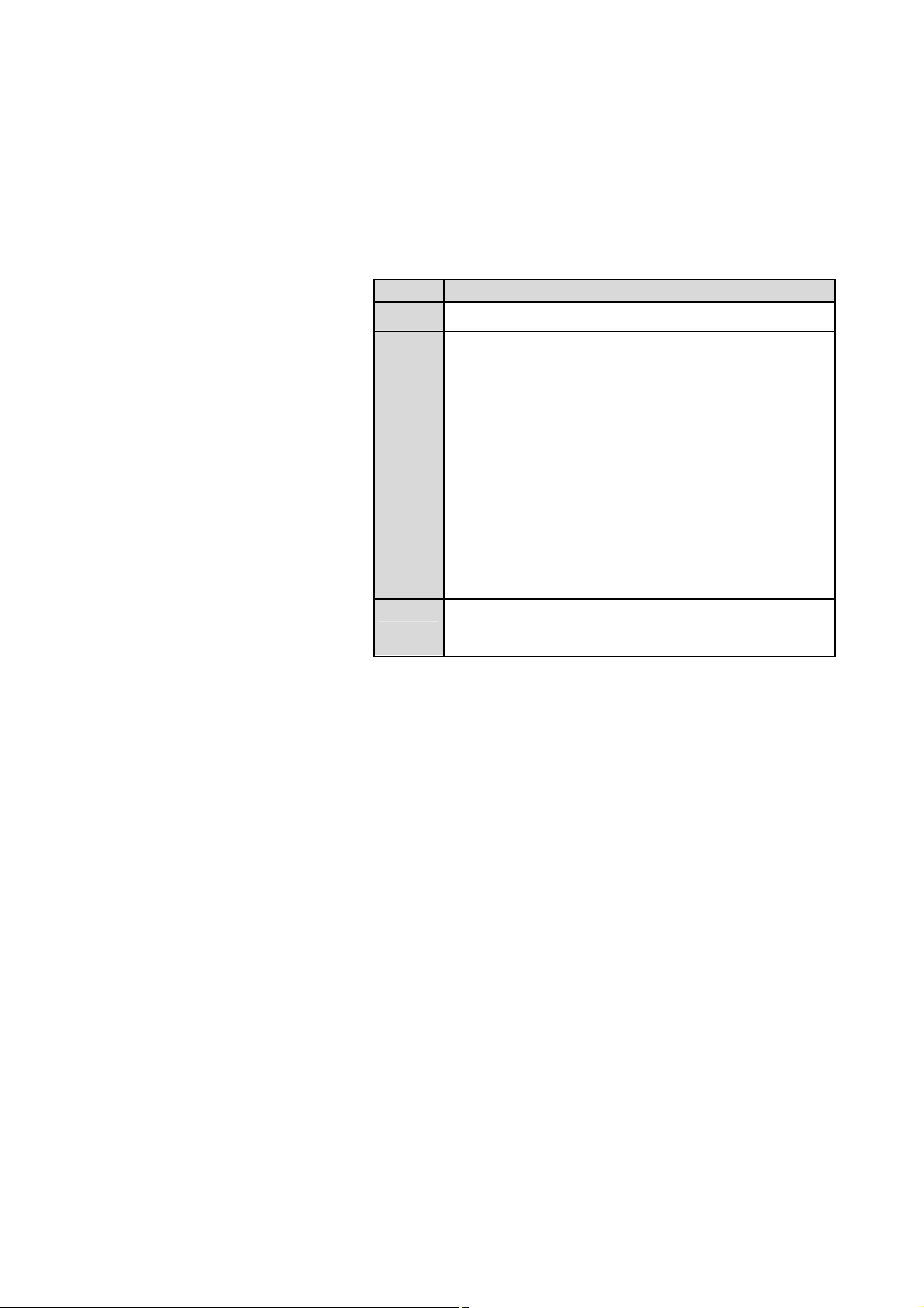
Danger levels
Signal word Meaning Consequences if not observed
DANGER
WARNING
CAUTION
Tab. 1
Other information and symbols
Warning, indicates the danger level.
Measures for avoiding the danger and its conse-
quences are specified here.
warns of immediate danger
warns of possible
danger
warns of a possibly
dangerous situation
Death or serious injuries
and/or serious damage are the
consequence.
Death or serious injuries
and/or serious damage are
possible.
Minor injuries or damage are
possible.
An activity to be carried out (a step) is specified here.
1. The first step of an activity to be carried out is specified here.
Additional, consecutively numbered steps follow.
This symbol refers to important information.
4 Translation of original Operating Instructions, english, KNF 121211-121345 01/10

LABOPORT Pumps and Systems Use
2. Use
2.1. Proper Use
The pump/system is exclusively intended for transferring gases
and vapors.
Owner's responsibility
Operating parameters and
conditions
Requirements for
transferred medium
High performance condenser
Accessories
Only install and operate the pump/system under the operating
parameters and conditions described in chapter 5, Technical data.
Make sure that the installation location is dry and the pump/system
is protected against rain, splash, hose and drip water.
Before using a medium, check the compatibility of the materials of
the pump head, diaphragm and valves with the medium.
Before using a medium, check whether the medium can be transferred danger-free in the specific application case.
Only transfer gases which remain stable under the pressures and
temperatures occurring in the pump.
The high performance condenser must be installed on the outlet
side of the pump; if it is installed on the inlet side there is a danger
of implosion.
Observe the correct usage of the gas- and cooling liquidconnections on the high performance condenser. Inlet and outlet
connections for the gas are not interchangeable.
Laboratory equipment or additional components connected to a
pump/system have to be suitable for use with the pneumatic capabilities of the pump (see chapter 5.1, page 10).
2.2. Improper Use
The pump/system may not be operated in an explosive atmosphere.
The pump/system is not suitable for transferring dusts.
The pump/system is not suitable for transferring liquids.
For LABOPORT systems with vacuum controller: The vacuum
system must not be used if the entry of air or gas into the vacuum
system during venting (pump vent valve) could result in the creation of reactive, explosive or otherwise hazardous mixtures (e.g.
with the medium).
The pump/the system must not be used to create vacuum and
overpressure simultaneously.
An overpressure must not be applied to the suction side of the
pump/ the system.
Translation of original Operating Instructions, english, KNF 121211-121345 01/10 5
Safety LABOPORT Pumps and Systems
3. Safety
Note the safety precautions in chapters 7. Installation, mounting and connection, and 8. Operation.
The pump/system is built according to the generally recognized
rules of technology and in accordance with the occupational safety
and accident prevention regulations. Nevertheless, dangers can
result during their use which lead to injuries to the user or others,
or to damage to the pump/system or other property.
Only use the pump/system when it is in a good technical and
proper working order, in accordance with its intended use, observing the safety advice within the operating instructions, at all times.
Personnel
Working in a safety-
conscious manner
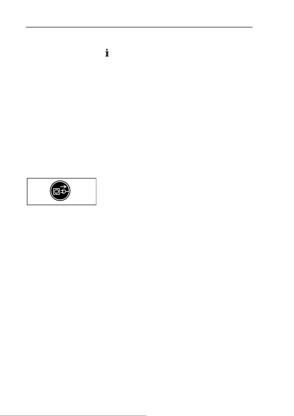
Fig. 1: Notice sticker
Handling dangerous media
Handling flammable media
Make sure that only trained and instructed personnel or specially
trained personnel work on the pump/system. This especially applies to assembly, connection and servicing work.
Make sure that the personnel has read and understood the operating instructions, and in particular the "Safety" chapter.
Observe the accident prevention and safety regulations when
performing any work on the pump/system and during operation.
Do not expose any part of your body to the vacuum.
Open housing parts with notice sticker (see fig. 1) only after
separating mains plug from power source.
When transferring dangerous media, observe the safety regulations when handling these media.
Be aware that the pump/system is not designed to be explosionproof.
Make sure the temperature of the medium is always sufficiently
below the ignition temperature of the medium, to avoid ignition or
explosion. This also applies for unusual operational situations.
Note that the temperature of the medium increases when the pump
compresses the medium.
Hence, make sure the temperature of the medium is sufficiently
below the ignition temperature of the medium, even when it is
compressed to the maximum permissible operating pressure of the
pump. The maximum permissible operating pressure of the pump
is stated in the technical specifications (see chapter 5.1, page 10).
If necessary, consider any external sources of energy, such as
radiation, that may add heat to the medium.
In case of doubt, consult the KNF customer service.
Environmental protection
6 Translation of original Operating Instructions, english, KNF 121211-121345 01/10
Store all replacement parts in a protected manner and dispose of
them properly in accordance with the applicable environmental
protection regulations. Observe the respective national and international regulations. This especially applies to parts contaminated
with toxic substances.

LABOPORT Pumps and Systems Safety
Standards
Customer service and
repairs
®
The KNF LABOPORT
pumps conform to the safety regulations of
the EC Directive 2004/108/EC concerning Electromagnetic Compatibility and the EC Directive 2006/42/EC concerning Machinery.
The requirements of the following harmonised standards are
fulfilled:
DIN EN 61010-1
DIN EN 61326-1
DIN EN 61000-3-2/3
The pumps correspond to IEC 664:
the overvoltage category II
the pollution degree 2
Only have repairs to the pump/system carried out by the KNF
Customer Service responsible.
Only authorized personnel should open those parts of the housing
that contain live electrical parts.
Use only genuine parts from KNF for servicing work.
Translation of original Operating Instructions, english, KNF 121211-121345 01/10 7

System overview LABOPORT Pumps and Systems
4. System overview
1 Electrical supply unit
2 Vacuum controller
3 Vent valve at vacuum
controller
4 On/off switch of vacuum
controller
5 Pump vent valve
6 Vacuum valve
7 High performance con-
denser
8 Hose connector
9 Angled nozzle for coolant
10 Spring clamp
11 Flask for condenser
12 Support for high perform-
ance condenser
13 Locating pin for pump
14 Separator
15 Holder for Separator
16 Support for vacuum control-
ler
17 Baseplate
18 Vacuum pump
19 On/off switch of pump
Fig. 2: Full expanded LABOPORT System SCC..., for example pump
model N 840.3 FT.18 (symbolic)
8 Translation of original Operating Instructions, english, KNF 121211-121345 01/10

LABOPORT Pumps and Systems System overview
Fig. 3: LABOPORT Systems
Module SR... SH... SC... SCC...
System
Pump X X X X
Baseplate X X X X
2 separators X
1 separator X X X
High performance
X X X
condenser
Electrical supply unit X X
1 vacuum controller X
2 vacuum controllers X
Tab. 2
Each pump and all systems can be expanded modularly up to
a full system SCC… (see chapter 7.7, page 28).
Translation of original Operating Instructions, english, KNF 121211-121345 01/10 9

Technical Data LABOPORT Pumps and Systems
5. Technical Data
5.1. Pumps
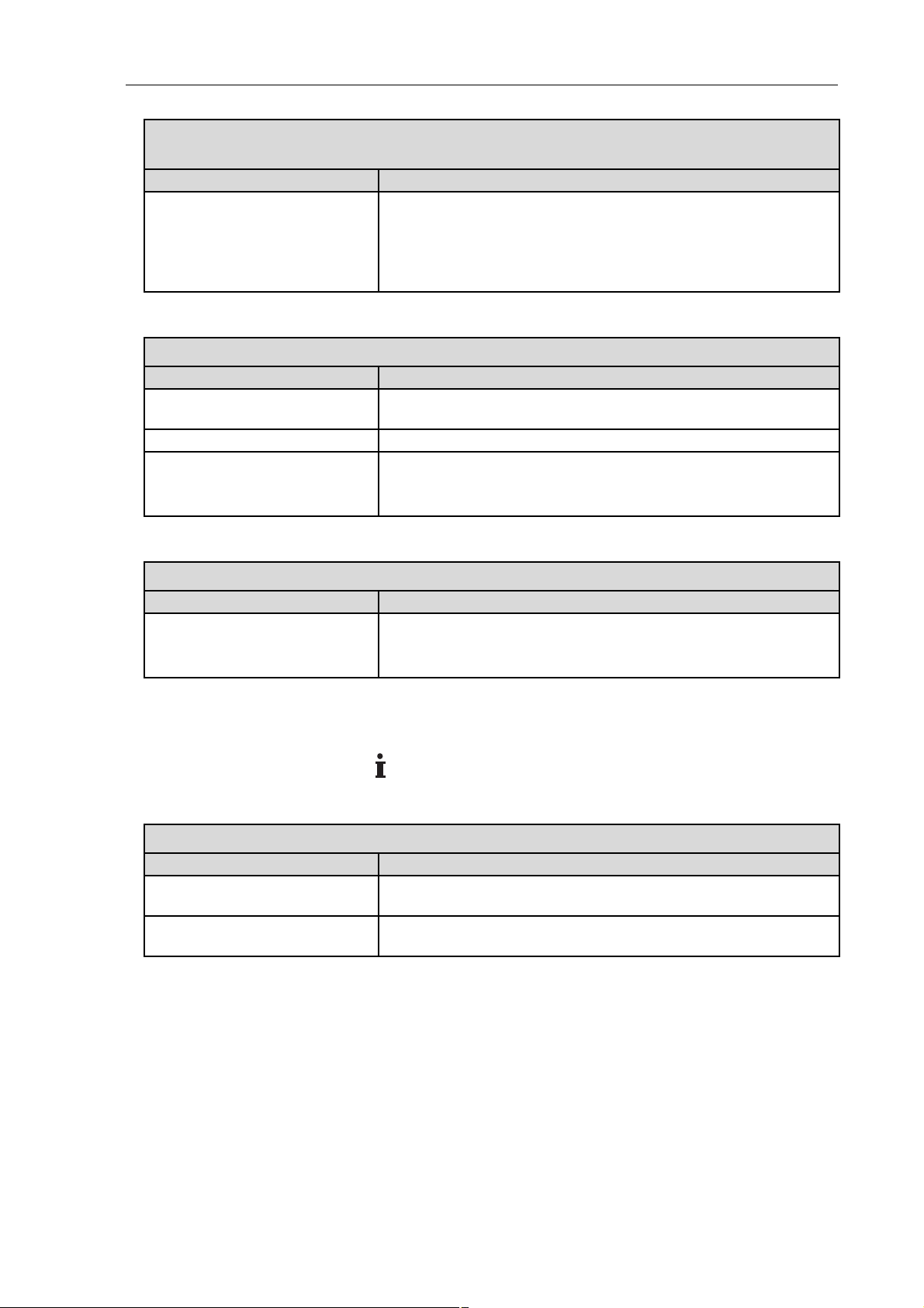
All pumps are secured against overheating with thermal
switches and are equipped with a mains fuse.
Pump materials (for all pump types) *
Pump head PTFE
Diaphragm PTFE coated
Valve FFPM
Tab. 3 *according to DIN ISO 1629 and 1043.1
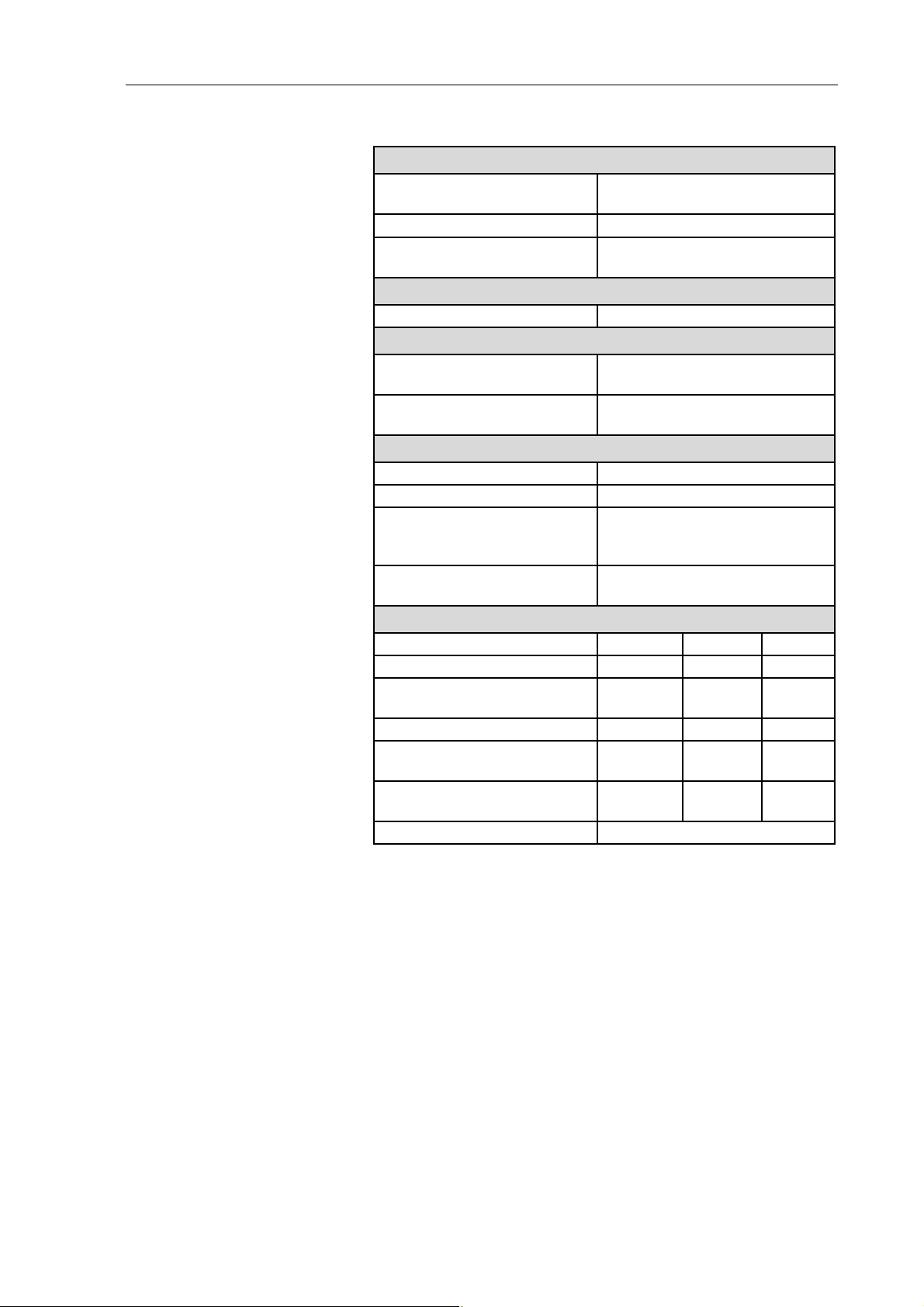
Refer to the type plate for the pump’s electrical configuration.
N 810 FT.18
Pneumatic performance
Max. permissible operating
1.0
pressure [bar g]
Ultimate vacuum [mbar abs.]
Delivery rate at atm. pressure
≤ 100
max. 10
[l/min]*
Pneumatic connection
Hose connection [mm] ID 10
Ambient and media temperature
Permissible
+ 5 °C to + 40 °C
ambient temperature
Permissible media temperatu-
+ 5 °C to + 40 °C
re
Other parameters
Weight [kg] 5.9
Dimensions: L x H x W [mm] 256 x 187 x 146
Maximum permissible ambient
relative humidity
80 % for temperatures up to
31 °C, decreasing linearly to
50 % at 40 °C
Maximum altitude of site
2000
[m above sea level]
Electrical Data
Voltage [V] 100 115 230
Frequency [Hz] 50/60 60 50
Maximum current consump-
1.4 1.3 0.6
tion [A]
Power consumption pump [W] 110 110 100
Maximum permitted mains
+/- 10 % +/- 10 % +/- 10 %
voltage fluctuation
Fuse pump
2.5 2.5 1.25
(2x) T [A]
Protection class motor IP44
Tab. 4 * Liters in standard state (1,013 mbar)
10 Translation of original Operating Instructions, english, KNF 121211-121345 01/10
LABOPORT Pumps and Systems Technical Data
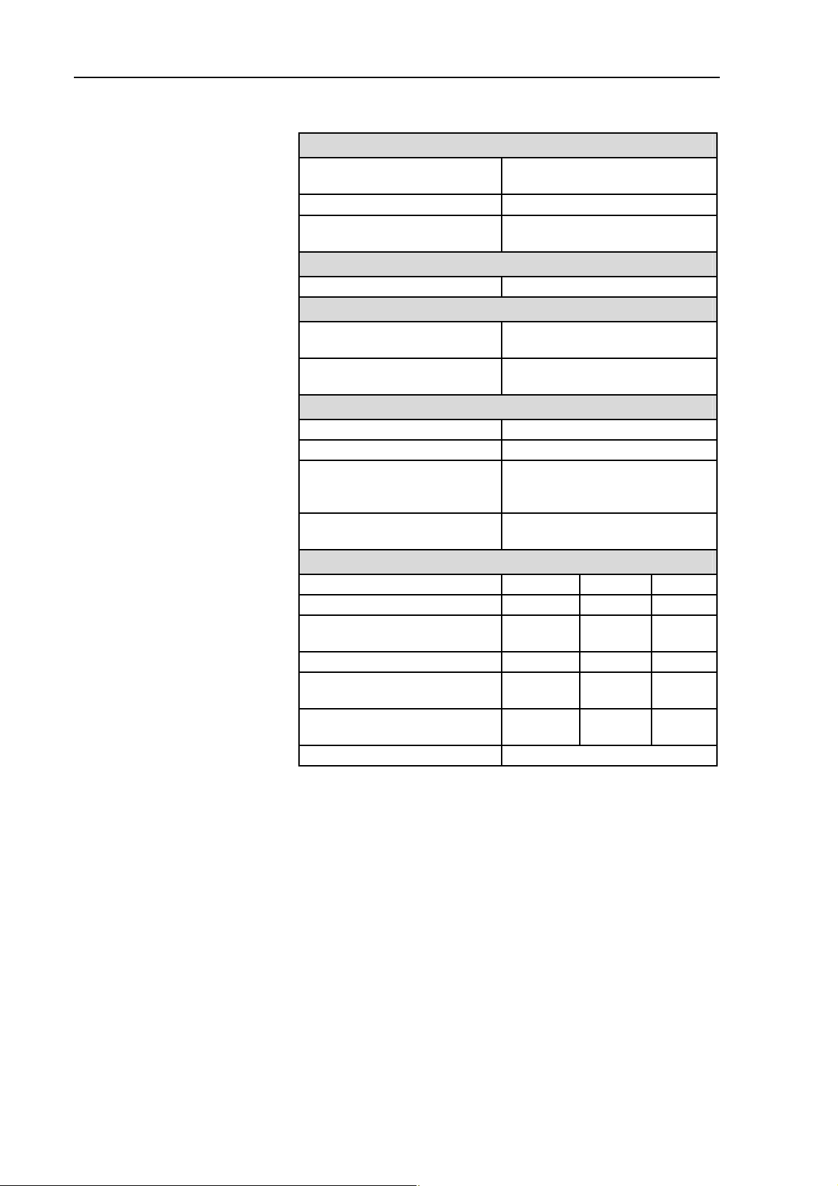
N 820 FT.18
Pneumatic performance
Max. permissible operating
1.0
pressure [bar g]
Ultimate vacuum [mbar abs.]
Delivery rate at atm. pressure
≤ 100
max. 20
[l/min]*
Pneumatic connection
Hose connection [mm] ID 10
Ambient and media temperature
Permissible
+ 5 °C to + 40 °C
ambient temperature
Permissible media temperatu-
+ 5 °C to + 40 °C
re
Other parameters
Weight [kg] 7.1
Dimensions: L x H x W [mm] 268 x 207 x 159
Maximum permissible ambient
relative humidity
80 % for temperatures up to
31 °C, decreasing linearly to
50 % at 40 °C
Maximum altitude of site
2000
[m above sea level]
Electrical Data
Voltage [V] 100 115 230
Frequency [Hz] 50/60 60 50
Maximum current consump-
2.2 1.9 0.9
tion [A]
Power consumption pump [W] 145 145 130
Maximum permitted mains
+/- 10 % +/- 10 % +/- 10 %
voltage fluctuation
Fuse pump
4.0 3.15 2.0
(2x) T [A]
Protection class motor IP44
Tab. 5 * Liters in standard state (1,013 mbar)
Translation of original Operating Instructions, english, KNF 121211-121345 01/10 11

Technical Data LABOPORT Pumps and Systems
N 840 FT.18
Pneumatic performance
Max. permissible operating
1.0
pressure [bar g]
Ultimate vacuum [mbar abs.]
Delivery rate at atm. pressure
≤ 100
max. 34
[l/min]*
Pneumatic connection
Hose connection [mm] ID 10
Ambient and media temperature
Permissible
+ 5 °C to + 40 °C
ambient temperature
Permissible media temperatu-
+ 5 °C to + 40 °C
re
Other parameters
Weight [kg] 10.3
Dimensions: L x H x W [mm] 297x 226 x 171
Maximum permissible ambient
relative humidity
80 % for temperatures up to
31 °C, decreasing linearly to
50 % at 40 °C
Maximum altitude of site
2000
[m above sea level]
Electrical Data
Voltage [V] 100 115 230
Frequency [Hz] 50/60 60 50
Maximum current consump-
4.4 3.2 1.5
tion [A]
Power consumption pump [W] 200 220 180
Maximum permitted mains
+/- 10 % +/- 10 % +/- 10 %
voltage fluctuation
Fuse pump
6.3 6.3 3.15
(2x) T [A]
Protection class motor IP44
Tab. 6 * Liters in standard state (1,013 mbar)N 810.3 FT.18
12 Translation of original Operating Instructions, english, KNF 121211-121345 01/10

LABOPORT Pumps and Systems Technical Data
N 810.3 FT.18
Pneumatic performance
Max. permissible operating
1.0
pressure [bar g]
Ultimate vacuum [mbar abs.]
Delivery rate at atm. pressure
≤ 8
max. 10
[l/min]*
Pneumatic connection
Hose connection [mm] ID 10
Ambient and media temperature
Permissible
+ 5 °C to + 40 °C
ambient temperature
Permissible media temperatu-
+ 5 °C to + 40 °C
re
Other parameters
Weight [kg] 6.9
Dimensions: L x H x W [mm] 281 x 187 x140
Maximum permissible ambient
relative humidity
80 % for temperatures up to
31 °C, decreasing linearly to
50 % at 40 °C
Maximum altitude of site
2000
[m above sea level]
Electrical Data
Voltage [V] 100 115 230
Frequency [Hz] 50/60 60 50
Maximum current consump-
1.4 1.3 0.6
tion [A]
Power consumption pump [W] 100 110 90
Maximum permitted mains
+/- 10 % +/- 10 % +/- 10 %
voltage fluctuation
Fuse pump
2.5 2.5 1.25
(2x) T [A]
Protection class motor IP44
Tab. 7 *Liters in standard state (1,013 mbar)
Translation of original Operating Instructions, english, KNF 121211-121345 01/10 13
Technical Data LABOPORT Pumps and Systems
N 820.3 FT.18
Pneumatic performance
Max. permissible operating
1.0
pressure [bar g]
Ultimate vacuum [mbar abs.]
Delivery rate at atm. pressure
≤ 8
max. 20
[l/min]*
Pneumatic connection
Hose connection [mm] ID 10
Ambient and media temperature
Permissible
+ 5 °C to + 40 °C
ambient temperature
Permissible media temperatu-
+ 5 °C to + 40 °C
re
Other parameters
Weight [kg] 9.3
Dimensions: L x H x W [mm] 312 x 207 x 144
Maximum permissible ambient
relative humidity
80 % for temperatures up to
31 °C, decreasing linearly to
50 % at 40 °C
Maximum altitude of site
2000
[m above sea level]
Electrical Data
Voltage [V] 100 115 230
Frequency [Hz] 50/60 60 50
Maximum current consump-
1.8 1.2 0.7
tion [A]
Power consumption pump [W] 130 130 120
Maximum permitted mains
+/- 10 % +/- 10 % +/- 10 %
voltage fluctuation
Fuse pump
3.15 2.5 1.6
(2x) T [A]
Protection class motor IP44
Tab. 8 *Liters in standard state (1,013 mbar)
14 Translation of original Operating Instructions, english, KNF 121211-121345 01/10

LABOPORT Pumps and Systems Technical Data
N 840.3 FT.18
Pneumatic performance
Max. permissible operating
1.0
pressure [bar g]
Ultimate vacuum [mbar abs.]
Delivery rate at atm. pressure
≤ 8
max. 34
[l/min]*
Pneumatic connection
Hose connection [mm] ID 10
Ambient and media temperature
Permissible
+ 5 °C to + 40 °C
ambient temperature
Permissible media temperatu-
+ 5 °C to + 40 °C
re
Other parameters
Weight [kg] 12.6
Dimensions: L x H x W [mm] 341 x 226 x 166
Maximum permissible ambient
relative humidity
80 % for temperatures up to
31 °C, decreasing linearly to
50 % at 40 °C
Maximum altitude of site
2000
[m above sea level]
Electrical Data
Voltage [V] 100 115 230
Frequency [Hz] 50/60 60 50
Maximum current consump-
4.4 3.2 1.5
tion [A]
Power consumption pump [W] 220 250 245
Maximum permitted mains
+/- 10 % +/- 10 % +/- 10 %
voltage fluctuation
Fuse pump
6.3 6.3 3.15
(2x) T [A]
Protection class motor IP44
Tab. 9 *Liters in standard state (1,013 mbar)
Translation of original Operating Instructions, english, KNF 121211-121345 01/10 15

Technical Data LABOPORT Pumps and Systems
N 840.1.2 FT.18
Pneumatic performance
Max. permissible operating
1.0
pressure [bar g]
Ultimate vacuum [mbar abs.]
Delivery rate at atm. pressure
≤ 90
max. 60
[l/min]*
Pneumatic connection
Hose connection [mm] ID 10
Ambient and media temperature
Permissible
+ 5 °C to + 40 °C
ambient temperature
Permissible media temperatu-
+ 5 °C to + 40 °C
re
Other parameters
Weight [kg] 12.6
Dimensions: L x H x W [mm] 341 x 226 x 160
Maximum permissible ambient
relative humidity
80 % for temperatures up to
31 °C, decreasing linearly to
50 % at 40 °C
Maximum altitude of site
2000
[m above sea level]
Electrical Data
Voltage [V] 100 115 230
Frequency [Hz] 50/60 60 50
Maximum current consump-
5.1 4.2 1.9
tion [A]
Power consumption pump [W] 275 280 270
Maximum permitted mains
+/- 10 % +/- 10 % +/- 10 %
voltage fluctuation
Fuse pump
6.3 6.3 3.15
(2x) T [A]
Protection class motor IP44
Tab. 10 *Liters in standard state (1,013 mbar)
16 Translation of original Operating Instructions, english, KNF 121211-121345 01/10

LABOPORT Pumps and Systems Technical Data
N 842.3 FT.18
Pneumatic performance
Max. permissible operating
1.0
pressure [bar g]
Ultimate vacuum [mbar abs.]
Delivery rate at atm. pressure
≤ 2
max. 34
[l/min]*
Pneumatic connection
Hose connection [mm] ID 10
Ambient and media temperature
Permissible
+ 5 °C to + 40 °C
ambient temperature
Permissible media temperatu-
+ 5 °C to + 40 °C
re
Other parameters
Weight [kg] 13.4
Dimensions: L x H x W [mm] 341 x 223 x 167
Maximum permissible ambient
relative humidity
80 % for temperatures up to
31 °C, decreasing linearly to
50 % at 40 °C
Maximum altitude of site
2000
[m above sea level]
Electrical Data
Voltage [V] 100 115 230
Frequency [Hz] 50/60 60 50
Maximum current consump-
4.4 3.2 1.5
tion [A]
Power consumption pump [W] 260 290 245
Fuse pump
6.3 6.3 3.15
(2x) T [A]
Protection class motor IP44
Tab. 11 *Liters in standard state (1,013 mbar)
5.2. Electrical Supply Unit
Electrical Data
Voltage [V] 100 115 230
Frequency [Hz] 50/60 60 50
Power consumption* [W] 270 300 295
Fuse pump
6.3 6.3 3.15
(2x) T [A]
Tab. 12
* includes the power consumption of the whole system (inclusive pump
and vacuum controller); for pumps N 840.1.2 FT.18 and N 842.3 FT.18
power consumption raises by approx. 50 W.
5.3. Vacuum Controller
See Operating Manual of the vacuum controller.
Translation of original Operating Instructions, english, KNF 121211-121345 01/10 17

Technical Data LABOPORT Pumps and Systems
5.4. Vacuum Systems
Ambient temperature
Permissible
+ 5 °C to + 40 °C
ambient temperature
Operating parameters of coolant (only for high performance condensers)
Permissible pressure [bar g] 3
Permissible temperature - 15 °C to + 20 °C
Condenser connectors For tube 8mm ID
Tab. 13
18 Translation of original Operating Instructions, english, KNF 121211-121345 01/10

LABOPORT Pumps and Systems Design and Function
6. Design and Function
6.1. Pump
Design
1 Connection piece
2 Pneumatic connection
3 Pump head
4 Outlet (pressure side)
5 Inlet (suction side)
6 Power switch
1 Outlet valve
2 Inlet valve
3 Transfer chamber
4 Diaphragm
5 Eccentric
6 Connecting rod
7 Pump drive
Fig. 4: Diaphragm pump (shown: pump N 840.3 FT.18)
Function Diaphragm pump
Fig. 5: Pump head
Diaphragm pumps transfer, compress (depending on pump version) and evacuate gases and vapors.
The elastic diaphragm (4) is moved up and down by the eccentric
(5) and the connecting rod (6). In the downward stroke it aspirates
the gas to be transferred via the inlet valve (2). In the upward
stroke, the diaphragm presses the medium out of the pump head
via the outlet valve (1). The transfer chamber (3) is hermetically
separated from the pump drive (7) by the diaphragm.
Translation of original Operating Instructions, english, KNF 121211-121345 01/10 19

Design and Function LABOPORT Pumps and Systems
6.2. Separator
Design
1 Tubing
2 Hose nozzle
3 Separator container
4 Holder for separator
1
2
3
4
Fig. 6: Separator (shown: LABOPORT system SR with pump
N 840.3 FT.18 as example)
Function
Condensable components in the gas can be separated on the
pressure side of the pump. On the suction side the separator
collects particular matter and droplets. This protects the pump from
contamination.
The separator is made of a specially treated glass and features
implosion protection.
20 Translation of original Operating Instructions, english, KNF 121211-121345 01/10

LABOPORT Pumps and Systems Design and Function
6.3. High Performance Condenser
Design
1 Hose nozzle
2 High Performance Con-
denser
3 Angled nozzle for coolant
4 Tubing
5 Spring clamp
6 Flask
7 Support
3
Fig. 7: High performance condenser (shown: LABOPORT system SH with
pump N 840.3 FT.18 as example)
Function
1
2
3
4
5
6
7
The high performance condenser at pump outlet enables condensable components in the vapour to be separated out.
The condensate is collected in a glass flask. The flask is attached
to the condenser flange with a clamp. The condensation temperature is maintained by running cold water or recirculated coolant
through the condenser.
Translation of original Operating Instructions, english, KNF 121211-121345 01/10 21

Design and Function LABOPORT Pumps and Systems
6.4. Vacuum Controller
1 Tubing
2 Power switch
3 Support
4 Electrical supply unit
5 Vacuum controller
5
5
4
Fig. 8: Vacuum controller (shown: LABOPORT system SCC with pump
N 840.3 FT.18 as example)
12231
Function
In laboratory systems without a vacuum controller the pump runs
continuously and works against its vacuum. If there is a vacuum
controller, it will switch the pump off once the selected target
vacuum has been reached.
With two vacuum controllers it becomes possible to simultaneously
run two different and independent processes with just one pump.
Once one vacuum controller’s set point has been reached, that
vacuum controller will close the valve it is controlling. If two
vacuum controllers are used, the pump will continue to work until
the second controller’s set point has been reached. Then the
second vacuum controller will close the valve it is controlling. The
pump switches off and the pump vent valve is opened.
If one of the two vacuum values falls below the hysteresis range,
the pump will switch back on.
Refer to the vacuum controller’s operating instructions for more
information.
22 Translation of original Operating Instructions, english, KNF 121211-121345 01/10

LABOPORT Pumps and Systems Installation, mounting and connection
7. Installation, mounting and connection
Only install and operate the pumps/systems under the operating
parameters and conditions described in chapter 5, Technical data.
Observe the safety precautions (see chapter 3, page 6).
Before installation, store the pump/the accessories at the
installation location to bring it up to room temperature.
Dimensions
Cooling air supply
Installation location
Connected components
Pump exhaust
See chapter 5, Technical data, for the dimensions of system.
Install the pump/system so that the motor fan can intake suffi-
cient cooling air.
Make sure that the installation location is dry and the
pump/system is protected against rain, splash, hose and drip
water.
Choose a safe location (flat surface) for the pump/system.
Protect the pump/system from dust.
Protect the pump/system from vibrations and jolts.
7.1. Connect pump
Only connect components to the pump which are designed for
the pneumatic data of the pump (see chapter 5.1, page 10).
If the pump is used as a vacuum pump, safely discharge the
pump exhaust at the pump’s pneumatic outlet.
A marking on the pump head shows the direction of flow.
1. Remove the protective plugs from the pneumatic connectors of
the pump.
2. Connect the suction line and pressure line.
3. Lay the suction and pressure line at a downward angle to
prevent condensate from running into the pump.
4. Insert the power cable’s plug into a properly installed
shockproof socket.
Translation of original Operating Instructions, english, KNF 121211-121345 01/10 23

Installation, mounting and connection LABOPORT Pumps and Systems
7.2. Baseplate
Condition
Fig. 9: Installation of the mounts at
the pump
Conditions
Tools and material
Pump disconnected from mains
1. Unscrew the pump`s rubber feet (1) anti-clockwise.
2. Install the mounts (2) onto the pump.
3. Stand the pump (fitted with the mounts) onto the baseplate
4. Aligne the mounts on the pump and the baseplate.
5. Slide the locating pin (see fig. 2/13) through the mount holes
on the baseplate and on the pump until they are fully engaged.
6. Check that the pump is securely fastened to the baseplate via
both mounts.
7.3. Separator
Baseplate mounted (see chapter 7.2)
Pump disconnected from mains
Qty Material
1 Phillips-head screwdriver No. 3
Tab. 14
1. Slide the container for the separator (see fig. 6/4) into the
baseplate’s upward-pointing slotted bar.
2. Fix the holders by tighten the screw in the bottom of them.
3. Place the glass separators into the holders.
Laying hoses: depending on system configuration see chapter
7.7.1 (system SR), 7.7.2 (system SH), 7.7.3 (system SC), 7.7.4
(system SCC) or 7.7.5 (retrofitting from system SC to system
SCC).
24 Translation of original Operating Instructions, english, KNF 121211-121345 01/10

LABOPORT Pumps and Systems Installation, mounting and connection
7.4. High Performance Condenser
The high performance condenser is delivered installed on a
support.
Conditions
Touls and material
Baseplate mounted (see chapter 7.2, page 24)
Pump disconnected from mains and de-energized
Qty Material
1 Allen key 5 mm
Tab. 15
Installing the high performance condenser
Danger of implosion if installed improperly
There is a danger of implosion if the high
performance condenser is installed on the pump
WARNING
1. Slide the support of high performance condenser (see fig. 7/7)
into the baseplate’s upward-pointing slotted bar.
inlet.
Connect the high performance condenser to the
pump outlet only.
Conditions
Tools and material
2. Fix the support to the baseplate by tightening the allen screw.
3. Align the high performance condenser so that the hose
connection at the inlet is lower than the pump outlet.
Laying hoses: depending on system configuration see chapter
7.7.2 (system SH), 7.7.3 (system SC), 7.7.4 (system SCC) or
7.7.5 (retrofitting from system SC to system SCC).
7.5. Electrical Supply Unit and Vacuum Controller
The vacuum controller(s) is (are) delivered with the ventilation
valve and pump vent valve installed on a support.
When retrofitting from system SC to system SCC, the second
vacuum controller is delivered complete with the ventilation
valve installed on a new support. Install the existing vacuum
controller on the new support. For more information about
retrofitting from system SC to system SCC, refer to chapter
7.7.5, page 32.
Baseplate mounted (see chapter 7.2, page 24)
Pump disconnected from mains
Qty Material
1 Allen key 4 mm
1 Allen key 5 mm
Tab. 16
Mounting the electrical supply unit
1. Slide the electrical supply unit (see fig. 8/4) with both tightening
nuts into the baseplate’s lateral slotted bar.
Translation of original Operating Instructions, english, KNF 121211-121345 01/10 25

Installation, mounting and connection LABOPORT Pumps and Systems
2. Tighten the allen screws at the bottom of the electrical supply
unit.
Mounting the vacuum controller
1. Slide the support’s attachment part (see fig. 8/3) into the
baseplate’s lateral, upward-pointing slotted bar.
2. Tighten the allen screw at the bottom of the support.
Wire and connect with each other the electrical supply unit
and the vacuum controller
Figures 11 and 12 provide an overview of the electrical
connections for LABOPORT systems SC and SCC.
1. Connect signal socket of the vacuum controller with the eletrical supply unit socket marked VC 1 (fig. 10/5) using the connection cable.
2. When using two vacuum controllers, connect the second
vacuum controller’s signal socket to the electrical supply unit’s
VC2 connection (6).
Fig. 10: Connections of the electri-
cal supply unit
3. Insert the vacuum controller power cord plug into the designated electrical supply unit socket (2).
4. When using two vacuum controllers, insert the vacuum valves’
plugs into the electrical supply unit’s VV1 (3) und VV2 (4)
connections.
5. Insert the pump vent valve plug into the electrical supply unit
socket marked PRV (7).
6. Insert the vacuum pump power cord plug into the designated
electrical supply unit socket (1).
7. Tuck all of the wires into the electrical supply unit and secure
the cover.
8. Make sure power switches on the pump and on the vacuum
controller(s) are switched off.
9. Insert the electrical supply unit`s system power cord plug into a
shockproof socket.
26 Translation of original Operating Instructions, english, KNF 121211-121345 01/10

LABOPORT Pumps and Systems Installation, mounting and connection
to vacuum pump
System
power
connect
Electrical
supply unit
Fig. 11: Electrical connection LABOPORT System SC
Vacuum
valve 1
to vacuum pump
System
power
connect
Vacuum
valve 2
Pump vent
valve
Pump vent
valve
Vacuum controller (rear)
Coolant valve (optional)
Vacuum controller 1 (rear)
Vacuum controller 2
Electrical
supply unit
Fig. 12: Electrical connection LABOPORT System SCC
Laying hoses: depending on system configuration see chapter
7.7.3 (system SC), 7.7.4 (system SCC) or 7.7.5 (retrofitting
from system SC to system SCC).
Mounting coolant valve for high performance condenser
(optional)
With a coolant valve it becomes possible to stop the flow of
coolant if the system’s control operation is interrupted or
terminated.
Danger of the high performance condenser bursting
Make sure that the coolant valve is mounted
between the coolant supply and the coolant inlet
WARNING
port of high performance condenser.
1. Connect the coolant valve to the coolant supply.
2. Insert the coolant valve’s plug into the vacuum
controller’s VV1 socket (see fig. 10/3).
See fig. 16, page 29 for coolant inlet and outlet.
Translation of original Operating Instructions, english, KNF 121211-121345 01/10 27

Installation, mounting and connection LABOPORT Pumps and Systems
7.6. Gas Ballast
Only for two-headed pumps.
Condition
12
4
Fig. 13: Mounting the gas ballast
Motor disconnected from mains and de-energized
Mounting
1. Disconnect the tubes from the inlet (4) and the outlet (3) of the
3
pump.
2. Remove the pump from the baseplate.
3. Open the connection (2) of the pump heads.
4. Screw out the connecting piece (1) of the vacuum side head.
5. Screw the gas ballast into the pump head.
6. Remount the connection (2) between the both pump heads.
7.7. Mounting of Systems
The displayed system tube configuration is for two-headed
pumps only.
Tools and material
Contact KNF Service for information about laying tubes for
one-headed pumps and pumps with aluminum heads (“A” in
the type designation).
7.7.1. System SR
The system SR consists of:
baseplate
two separators
Qty Material
1 Phillips-head screwdriver No. 3
2 Tubes (see fig. 14)
Resistant to the medium employed
Inside diameter 10 mm
Length: approx. 150 mm
Tab. 17
1. Attach pump to the baseplate (see chapter 7.2, page 24).
2. Install the separators (chapter 7.3, page 24).
3. Lay tubes for separators (see fig. 14).
Fig. 14: Tubing system SR
28 Translation of original Operating Instructions, english, KNF 121211-121345 01/10

LABOPORT Pumps and Systems Installation, mounting and connection
7.7.2. System SH
The system SH consists of:
Baseplate
1 separator
1 high performance condenser
Tools and material
Qty Material
1 Phillips-head screwdriver No. 3
1 Allen key 5 mm
2 Tubes (see fig. 15)
Resistant to the medium employed
Inside diameter 10 mm
Length: (1) approx. 150 mm, (2) approx. 220 mm
Tab. 18
Danger of the high performance condenser bursting
Make sure that the high performance con-
denser´s upper gas outlet is not blocked.
WARNING
Fig. 15: Tubing system SH
Fig. 16: Coolant supply of high
performance condenser
Improper laying of hoses will result in damage to the
pump
Correctly assign gas and coolant hose
DANGER
connections.
Do not reverse the gas connections’ inlets and
outlets.
1. Attach pump to the baseplate (see chapter 7.2, page 24).
2. Install the separator (see chapter 7.3, page 24).
3. Install the high performance condenser (see chapter 7.4, page
25).
4. Lay hoses for system (see fig. 15).
The condenser-connectors for the coolant require connection
tubing with an inside diameter of 8 mm.
Coolant inlet and outlet see fig. 16.
When using a coolant valve:
Danger of the high performance condenser bursting
WARNING
Make sure that the coolant valve is mounted
between the coolant supply and the coolant inlet
port of high performance condenser.
1 Coolant inlet
2 Coolant outlet
Translation of original Operating Instructions, english, KNF 121211-121345 01/10 29

Installation, mounting and connection LABOPORT Pumps and Systems
7.7.3. System SC
The system SC consists of:
Baseplate
1 separator
1 high performance condenser
Electrical supply unit with 1 vacuum controller
Tools and material
Qty Material
1 Phillips-head screwdriver No. 3
1 Allen key 4 mm
1 Allen key 5 mm
4 Tubes (see fig. 17)
Resistant to the medium employed
Inside diameter 10 mm
Length: (1,4) approx. 220 mm, (2) approx. 300 mm,
(3) approx. 150 mm
Tab. 19
1. Attach pump to the baseplate (see chapter 7.2, page 20).
Fig. 17: Tubing system SC
2. Install the separator (see chapter 7.3, page 20).
3. Install the high performance condenser (see chapter 7.4, page
21).
4. Install the electrical supply unit and the vacuum controller (see
chapter 7.5, page 21).
5. Lay hoses for system (see fig. 17).
Coolant inlet and outlet see fig. 16.
When using a coolant valve:
Danger of the high performance condenser bursting
Make sure that the coolant valve is mounted
between the coolant supply and the coolant inlet
WARNING
port of high performance condenser.
6. Wire and connect with each other the electrical supply unit and
the vacuum controller (see chapter 7.5, page 21).
30 Translation of original Operating Instructions, english, KNF 121211-121345 01/10

LABOPORT Pumps and Systems Installation, mounting and connection
7.7.4. System SCC
The system SCC consists of:
Baseplate
1 separator
1 high performance condenser
Electrical supply unit with 2 vacuum controllers
Tools and material
Qty Material
1 Phillips-head screwdriver No. 3
1 Allen key 4 mm
1 Allen key 5 mm
8 Tubes (see fig. 18)
Resistant to the medium employed
Inside diameter 10 mm
Length: (1) approx. 320 mm, (2) approx. 260 mm,
(3,4) approx. 120 mm, (5) approx. 220 mm, (6) approx.
135 mm, (7) approx. 175 mm, (8) approx. 350 mm
Tab. 20
1. Attach pump to the baseplate (see chapter 7.2, page 20).
Fig. 18: Tubing system SCC
2. Install the separator (see chapter 7.3, page 20).
3. Install the high performance condenser (see chapter 7.4, page
21).
4. Install the electrical supply unit and both vacuum controllers
(see chapter 7.5, page 21).
5. Lay hoses for system (see fig. 18).
Coolant inlet and outlet see fig. 16.
When using a coolant valve:
Danger of the high performance condenser bursting
Make sure that the coolant valve is mounted
between the coolant supply and the coolant inlet
WARNING
port of high performance condenser.
6. Wire and connect with each other the electrical supply unit and
the vacuum controller (see chapter 7.5, page 21).
Translation of original Operating Instructions, english, KNF 121211-121345 01/10 31

Installation, mounting and connection LABOPORT Pumps and Systems
7.7.5. Retrofitting from System SC to System SCC
The second vacuum controller is delivered complete with the
vent valve installed on a new support (length: 410 mm). Install
the existing vacuum controller on the new support.
Conditions
Pump removed from operation (see chapter 8.2, page 35)
Pump disconnected from mains
Tools and material
Qty Material
1 Allen key 4 mm
1 Allen key 5 mm
See chapter 7.7.4 for the required hoses
Tab. 21
Removing the existing vacuum controller
The following item numbers refer to fig. 2, page 8.
1. Disconnect the tubes from the pump vent valve (5) as well as
from the controller (2) vent valve (3).
Fig. 19: Tubing system SCC
2. Pull out all plugs from the electrical supply unit (1).
3. Remove the vacuum controller from the support (16) after
loosening the clamp assembly.
4. Remove the lateral support from the main support after loosening the clamp assembly.
5. Loosen the allen screw at the foot of the main support.
6. Slide the support out of the baseplate (17) mounting slot assembly.
Mount new vacuum controller
The following item numbers refer to fig. 2, page 8.
1. Slide the removed vacuum controller (2) into the slot on the
new support (16) and fix it in place with the clamp connection.
2. Slide the support’s attachment part into the baseplate’s (17)
lateral upward-pointing slotted bar.
3. Tighten the allen screw at the foot of the support.
4. Mount the lateral support onto the main support.
5. Slide two additional vacuum valves(6) onto the lateral support
mounting slot and fix the device with help of the clamping assembly.
6. Lay hoses for system (see fig. 19).
7. Wire and connect with each other the electrical supply unit and
the vacuum controller (see chapter 7.5, page 25).
32 Translation of original Operating Instructions, english, KNF 121211-121345 01/10
LABOPORT Pumps and Systems Operation
8. Operation
8.1. Pump
8.1.1. Preparing for Start-up
Before switching on the pump/system, observe the following
points:
Operational requirements
Pump All hoses attached properly
Pump/
System
System Clamp connections are tight
Tab. 22
8.1.2. Starting
Only operate the pump under the operating parameters and
conditions described in chapter 5, Technical data.
Make sure the pumps are used properly (see chapter 2.1,
page 5).
Fan openings not blocked
Specifications of the power supply correspond with
the data on the pump’s/the electrical supply unit’s
type plate.
The pump outlet is not closed or constricted.
When using two vacuum controllers: The media
are compatible with each other (when running two
different processes simultaneously)
When using a gas ballast: No explosive or
poisonous mixtures may be produced when
ventilating the vacuum system through the air inlet.
All cables attached properly
Make sure the pumps are not used improperly (see chapter
2.2, page 5).
Observe the safety precautions (see chapter 3, page 6).
Translation of original Operating Instructions, english, KNF 121211-121345 01/10 33

Operation LABOPORT Pumps and Systems
A
Hazard of the pump head bursting due to excessive
pressure increase
Do not exceed max. permissible operating
WARNING
Excessive pressure (with all of the related hazards) can be
prevented by placing a bypass line with a pressure-relief valve
pressure (see chapter 5.1, page 10).
Monitor pressure during operation.
If the pressure exceeds the maximum permissi-
ble operating pressure, immediately shut down
pump and eliminate fault (see chapter 10, page
42).
Only throttle or regulate the air or gas quantity in
the suction line to prevent the maximum permissible operating pressure from being exceeded.
If the air or gas quantity in the pressure line is
throttled or regulated, make sure that the maximum permissible operating pressure of the
pump is not exceeded.
between the pressure and suctions sides of the pump. For
further information, contact our technical adviser.
Pump standstill
With the pump at a standstill, open pressure and suction lines
to normal atmospheric pressure.
Automatic starting can cause personal injury and
pump damage
When the operation of the pump is interrupted by the
WARNING
thermal switch, the pump will restart automatically
after cooling down.
fter triggering of the thermal protection or in the
event of power failure, remove the pump’s mains
plug from the socket so that the pump cannot
start uncontrollably.
Attempt work on the pump or system only if the
pump/system is separated from mains power.
34 Translation of original Operating Instructions, english, KNF 121211-121345 01/10

LABOPORT Pumps and Systems Operation
r
8.2. Switching Pump/System on and off
Switching pump on
The pump may not start up against overpressure during
switch-on. This also applies in operation following a brief powe
failure. If a pump starts against pressure, it may block. This
activates the thermal switch, and the pump switches off.
Make sure that no pressure is present in the lines during
switch-on.
Switch on pump with mains switch (see fig. 2/19)
Switching off the pump/removing from operation
When transferring aggressive media, flush the pump prior to
switch-off to increase the service life of the diaphragm (see
chapter 9.2.1, page 37).
Switch off pump with mains switch (see fig. 2/19).
Open pressure and suction lines to normal atmospheric pres-
sure.
Tools and material
Disconnect the power source.
8.3. Notices related to System Operation
8.3.1. Separators
You can move the holders for the separator vessels after
loosening the attachment screw.
8.3.2. High Performance Condenser
Danger of high performance condenser bursting
Make sure that the high performance
condenser’s upper gas outlet is not blocked.
CAUTION
A high performance condenser may be used only with a coldwater connection or recirculated cooling system.
Adjustment of the high performance condenser altitude level
Qty Material
1 Allen key 5 mm
Tab. 23
1. Loosen the both allen screws at the foot of the high performance condenser.
2. Remove the high performance condenser’s clamp assembly in
the support mounting slot.
3. Retighten the allen screws.
Translation of original Operating Instructions, english, KNF 121211-121345 01/10 35

Operation LABOPORT Pumps and Systems
p
8.3.3. Vacuum Controller
Personal injury caused by poisoning or explosion
and damage to the pump.
Make sure that no reactive or explosive mixtures
WARNING
will be produced when ventilating the vacuum
system through the air inlet.
Make sure that the media are compatible with
each other (when running two different
processes simultaneously).
Use the mains switch to switch the vacuum controller on and
off.
Each vacuum controller can be set individually and will work
independently of the other.
Refer to the vacuum controller’s operating instructions for more
information.
8.3.4. Gas Ballast
closed
o
en
Fig. 20: Gas ballast operating
knob
Personal injury caused by poisoning or explosion
and damage to the pump.
Ensure that the creation of reactive, explosive or
WARNING
otherwise hazardous mixtures during the supply
of air is prevented.
If the gas ballast valve is open the maximum achievable vacuum level is reduced. The gas ballast is adjusted with the
button (see fig. 20).
36 Translation of original Operating Instructions, english, KNF 121211-121345 01/10

LABOPORT Pumps and Systems Servicing
9. Servicing
9.1. Servicing Schedule
Component Servicing interval
Pump/system Regular inspection for external damage or
leaks
Diaphragm and
valve
plates/sealings
Tab. 24
9.2. Cleaning
When cleaning, make sure that no liquids enter the inside of
the housing.
9.2.1. Flushing Pump
Before switching off the pump, flush it with air (if necessary for
safety reasons: with an inert gas) for about five minutes under
atmospheric conditions (ambient pressure).
9.2.2. Cleaning Pump
Replace at the latest, when pump output
decreases
Only clean pump with a damp cloth and non-flammable clean-
ing agents.
9.2.3. Emptying and Cleaning the Separator
1. Unscrew the connecting nozzles (fig. 2/8, page 8).
2. Remove separator (fig. 2/14) from the holder (fig. 2/15) and
dispose of contents according to applicable regulations in your
area. Then rinse out the separator.
3. Replace separator into the holder.
4. Screw the connecting nozzles back on.
9.2.4. Emptying and Cleaning the Condenser
1. Carefully remove the spring clamp (fig. 2/10) while supporting
the flask (fig. 2/11).
2. Empty and clean the flask – observing safety precautions.
3. Re-connect the flask to the condenser and replace the spring
clamp.
Translation of original Operating Instructions, english, KNF 121211-121345 01/10 37

Servicing LABOPORT Pumps and Systems
9.3. Changing Diaphragm and Valve
Plates/Sealings
Conditions
Tools and material
Information on procedure
Pump is switched off and mains plug is removed from the
socket
Pump is clean and free of hazardous materials
Tubes removed from pump’s pneumatic inlet and outlet
Pump is removed from baseplate (if pump is integrated into a
system)
Qty Material
1 Phillips-head screwdriver No. 2
1 Service Set (see chapter 11.1, page 46)
1 Felt-tip pen
Tab. 25
Always replace diaphragm and valve plates/sealings together
to maintain the pump performance.
With multi-head pumps, parts of the individual pump heads can be
confused.
Replace the diaphragm and valve plates/sealings of the indi-
vidual pump heads consecutively.
Health hazard due to dangerous substances
in the pump!
WARNING
Depending on the substance transferred, caustic
burns or poisoning are possible.
Wear protective clothing if necessary, e.g.
protective gloves.
Flush pump before replacing the diaphragm and
valve plates/sealings (see chapter 9.2.1, page
37).
38 Translation of original Operating Instructions, english, KNF 121211-121345 01/10

LABOPORT Pumps and Systems Servicing
Removing pump head
Pump N 842.3 FT.18 has a round shape of head, not a
hexagonal.
1. For two-headed pumps: On the pneumatic head connection
(3), loosen the union nuts (2) by hand. Then slightly loosen the
angle-fitting (1) in the pump head (4) by turning it anticlockwise, so that the connecting tube can be pulled out.
2. Mark the position of top plate (fig. 24/5), head plate (fig. 24/6),
intermediate plate (fig. 24/8) and adapter relatively to each
other by a drawing line (for two-headed pumps: at both pump
heads) with a felt-tip pen (1). This helps to avoid incorrect assembly later.
Fig. 21: Removing pump head
be loosened in the next work step.
3. Loosen the outer screws (5) on the pump head/pump heads.
In version N 842.3 FT.18, twelve (instead of six) screws must
4. Carefully remove pump head / pump heads.
Change diaphragm
Fig. 22: Changing structured
diaphragm
Replace the diaphragms of two-headed pumps consecutively
in order to ensure that the same number of diaphragm spacers
is used as before.
1. For two-headed pumps: Push down one diaphragm until other
diaphragm is pushed upwards to its highest position.
2. Carefully unscrew the upper diaphragm (1) anti-clockwise
using both hands.
3. Replace spacer thick (2) and spacers thin (3) onto the screw
thread of the new diaphragm (same number and order).
4. Screw in the new diaphragm and tighten it by hand.
5. With a two-headed pump: Complete steps 1 through 4 for the
second pump head.
Translation of original Operating Instructions, english, KNF 121211-121345 01/10 39

Servicing LABOPORT Pumps and Systems
Change valve plates/sealings
Replacing the valve plates/sealings of two-headed pumps
consecutively.
In version N 842.3 FT.18, three (instead of one) screws must
be loosened in the first work step.
1. Loosen screw(s) (1) in the center of the top plate (2). With a
two-headed pump: loosen the screw(s) from just one pump
head.
2. Remove top plate (2) and head plate (3) from intermediate
plate (5).
Valve plates/sealings are visible.
3. Remove old valve plate/sealings.
Fig. 23: Changing valve
plates/sealings
1
2
3
4
5
6
7
8
Fig. 24: Refitting pump head
4. Clean intermediate plate (5) carefully (if there should be depos-
its in the recesses in the intermediate plate).
5. Insert new valve plates/sealings (4) in the recesses in the
intermediate plate (5).
6. For two-headed pumps: Carry out the steps 1 to 5 for the
second pump head.
7. Dispose of the old diaphragm(s) and valve plates/sealings
properly.
Refitting pump head
1. Apply pressure all around the edge of the diaphragm. With a
two-headed pump: Apply pressure to diaphragm on only one
pump.
2. Place the intermediate plate (8) with valve plates/sealings on
the adapter in accordance with the felt-tip pen marking.
3. Place the head plate (6) on the intermediate plate (8) in the
position indicated by the guide pin (7).
4. Place the top plate (5) on the head plate (6) in accordance with
the felt-tip pen marking.
5. Gently tighten screws (4) in diagonal order.
In version N 842.3 FT.18, three (instead of one) screws must
be tightened in the next work step.
6. Insert screw(s) (1) with disk springs (2, 3) in the center of the
top plate (5). In doing so, make sure that the disk springs are
arranged properly (see fig. 24).
7. Screw in the screw/screws (1) in the centre of the pump top
plate (5) until it is flush with the top plate (they are flush with
the top plate); then screw one final half turn to tighten.
8. For two-headed pumps: Carry out steps 1 to 7 for the second
pump head.
9. For two-headed pumps: Refit the pneumatic head connection:
Place tube onto the connecting part of the angle fitting, turn
angle fitting to a straight position and tighten the union nut.
40 Translation of original Operating Instructions, english, KNF 121211-121345 01/10

LABOPORT Pumps and Systems Servicing
Final steps
1. Remount the pump to the baseplate (if applicable).
2. Reconnect suction and pressure line to the pump.
3. Reconnect the pump to the electricity supply.
Translation of original Operating Instructions, english, KNF 121211-121345 01/10 41

Troubleshooting LABOPORT Pumps and Systems
10. Troubleshooting
Extreme danger from electrical shock!
Disconnect the pump power supply before working
on the pump.
DANGER
Check the pump (see Tab. 26 to 35).
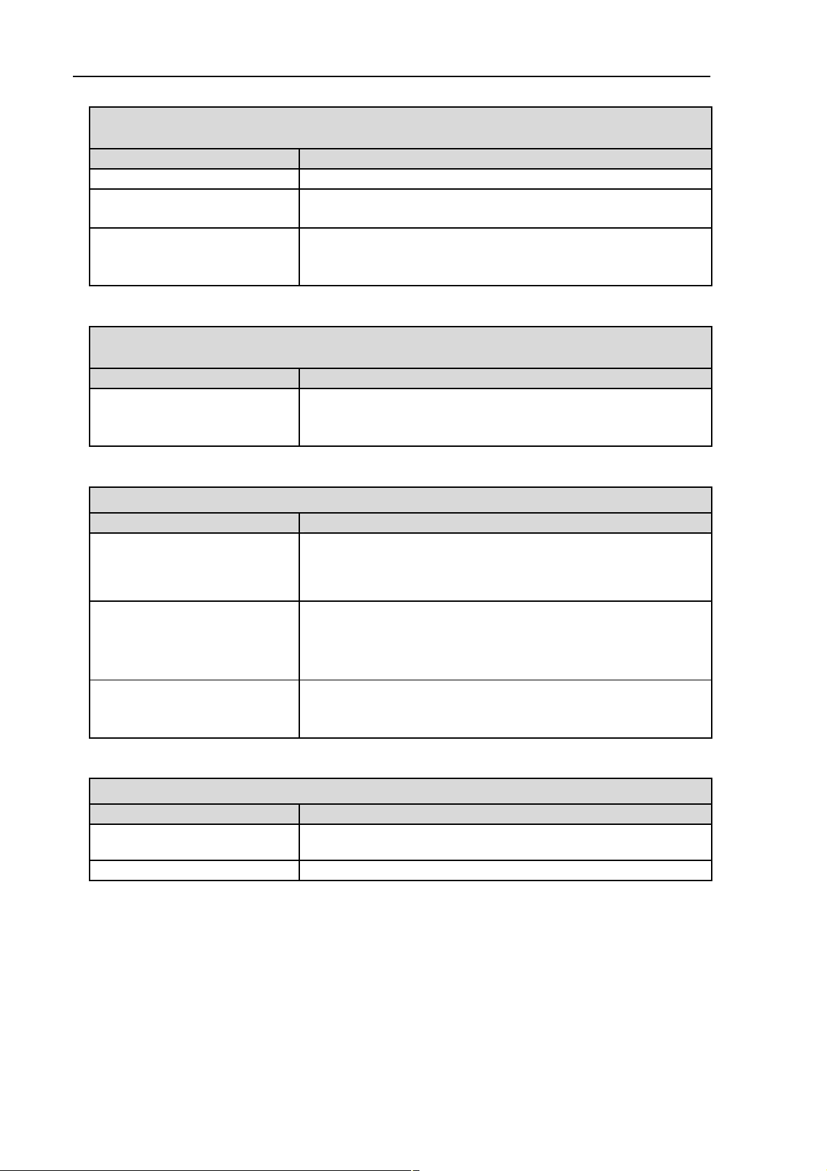
10.1. Pump/System without Vacuum Controller
Pump does not transfer
Cause Fault remedy
No voltage in the power source Check room fuse and switch on if necessary.
Make sure the pump is de-energized and secure.
Thermal switch has operated
following to over-heating.
Connections or lines blocked. Check connections and lines.
External valve is closed or filter
is clogged.
Condensate has collected in
pump head.
Diaphragm or valve plates/
sealings are worn.
Flow rate, pressure or vacuum too low
The system/the pump does not achieve the output specified in the Technical data or the data sheet.
Cause Fault remedy
Condensate has collected in
pump head.
There is gauge pressure on
pressure side and at the same
time vacuum or a pressure
above atmospheric pressure on
suction side.
Pneumatic lines or connection
parts have an insufficient cross
section or they are throttled.
Leaks occur on connections,
lines or pump head.
Connections or lines completely
or partially jammed.
Head parts are soiled. Clean head components.
Disconnect pump from mains.
Allow pump to cool.
Trace cause of over-heating and eliminate it.
Remove blockage.
Check external valves and filters.
Detach the condensate source from the pump.
Flush pump (see chapter 9.2.1, page 37).
Replace diaphragm and valve plates/sealings (see chapter
9.3, page 38).
Tab. 26
Detach the condensate source from the pump.
Flush pump (see chapter 9.2.1, page 37).
Change the pressure conditions.
Disconnect pump from system to determine output values.
Eliminate throttling (e.g. valve) if necessary.
Use lines or connection parts with larger cross section if
necessary.
Check that tubes sit correctly on hose nozzles.
Replace leaky tubes.
Eliminate leaks.
Check connections and lines.
Remove the jamming parts and particles.
Diaphragm or valve
plates/sealings are worn.
42 Translation of original Operating Instructions, english, KNF 121211-121345 01/10
Replace diaphragm and valve plates/sealings,
(see chapter 9.3, page 38).
LABOPORT Pumps and Systems Troubleshooting
Flow rate, pressure or vacuum too low
The system/the pump does not achieve the output specified in the Technical data or the data sheet.
Cause Fault remedy
After diaphragm and valve
plates/sealings have been
replaced.
Check that the spacers have been replaced onto the dia-
phragm screw thread.
Check head connection and hose connections.
Possibly carefully tighten the outer screws (fig. 21/5, page
39) of the top plate crosswise.
Tab. 27
Pump is switched on, but does not run, the on/off-switch on the pump is not lit
Cause Fault remedy
Pump is not connected with the
Connect pump to mains power.
power source.
No voltage in the power source
Fuse in the pump is defective.
Check room fuse and switch on if necessary.
Remove pump’s mains plug from the socket.
Loosen marked lid on underside of the pump.
Select and replace suitable fuse (see chapter 5.1, page 10).
Tab. 28
Pump is switched on, but does not run, the on/off-switch on the pump is lit
Cause Fault remedy
The thermal switch has opened
due to overheating.
Remove pump’s mains plug from the socket.
Allow pump to cool.
Trace cause of over-heating and eliminate it.
Tab. 29
10.2. System with one Vacuum Controller
See also chapter 10.1, pump/system without vacuum
controller, table 26 and 27.
Sufficient vacuum is not reached
Cause Fault remedy
Solid particles in the pump vent
valve
Condensate in pump head
Clean pump vent valve.
Let the pumpe run to the ultimate vacuum (Drying Mode, see
Operating Manual of Vacuum Controller).
Tab. 30
Translation of original Operating Instructions, english, KNF 121211-121345 01/10 43
Troubleshooting LABOPORT Pumps and Systems
Vacuum Controller is switched on and set on "Regulation Mode", the desired vacuum level
is not reached, pump does not run, the on/off-switch on the pump is not lit
Cause Fault remedy
Pump is not switched on.
Incorrect electrical connection of
controller
Fuse in the pump is defective.
Switch on pump.
Switch off system and separate from power supply.
Check cabling.
Remove pump’s mains plug from the socket.
Loosen marked lid on underside of the pump.
Select and replace suitable fuse (see chapter 5.1, page 10).
Tab. 31
Vacuum Controller is switched on and set on "Regulation Mode", the desired vacum level is
not reached, pump does not run, the on/off-switch on the pump is lit
Cause Fault remedy
The thermal switch has opened
due to overheating.
Remove pump’s mains plug from the socket.
Allow pump to cool.
Trace cause of over-heating and eliminate it.
Tab. 32
Vacuum Controller is switched on, no LED-indication
Cause Fault remedy
In the electrical supply unit the
vacuum controller plug is
plugged into the socket for the
Make sure that the vacuum controller’s mains plug is plugged
into the socket (on the electrical supply unit) for vacuum
controllers (see fig. 10, page 26, position 2).
pump.
The fuse in the vacuum control-
ler is defective.
Switch off system and separate from power supply.
Select an appropriate fuse (refer to the vacuum controller’s
operating instructions).
Replace fuse above the circuit closer/circuit breaker.
The fuse in the electrical supply
unit is defect.
Switch off system and separate from power supply.
Select suitable fuse (see chapter 5.2, page 17).
Replace fuse on the front side, below the mains connection.
Tab. 33
Vacuum Controller shows unrealistic values
Cause Fault remedy
The factory-set pressure
Contact KNF (see page 47).
equalization has changed.
Sensor is defective Contact KNF (see page 47).
Tab. 34
44 Translation of original Operating Instructions, english, KNF 121211-121345 01/10

LABOPORT Pumps and Systems Troubleshooting
10.3. System with two Vacuum Controllers
See also chapter 10.2, system with one vacuum controller.
System does not work, despite one Vacuum Controller (both controllers) being set on
"Regulation Mode"
Cause Fault remedy
In the electrical supply unit the
connecting wires for the vacuum
controllers are plugged in incorrectly.
In the electrical supply unit the
connecting wires for the vacuum
valve are plugged incorrectly.
Exchange the plugs between vacuum controller 1 and vac-
uum controller 2.
Exchange the plugs between vacuum valve 1 and vacuum
valve 2.
Tab. 35
10.4. Fault cannot be rectified
If you are unable to determine any of the specified causes, send
the pump to KNF Customer Service (see page 47 for the address).
1. Flush the pump to free the pump head of dangerous or ag-
gressive gases (see chapter 9.2.1, page 37).
2. Remove the pump.
3. Clean the pump (see chapter 9.2.2, page 37).
4. Send the pump to KNF with a filled out decontamination decla-
ration (see chapter 12) and specification of the medium transferred.
Translation of original Operating Instructions, english, KNF 121211-121345 01/10 45

Ordering Information LABOPORT Pumps and Systems
11. Ordering Information
11.1. Pumps and Spare Parts
A service set contains:
1 diaphragm and 2 valve plates/sealings for one-headed
pumps
2 diaphragms and 4 valve plates/sealings for two-headed
pumps
Pump type Order-No. pump Order-No. Service Set
N 810 FT.18 057986 058077
N 820 FT.18 057901 058078
N 840 FT.18 057911 058079
N 810.3 FT.18 057500 057357
N 820.3 FT.18 057501 057358
N 840.3 FT.18 057502 057359
N 840.1.2 FT.18 057571 057359
N 842.3 FT.18 057634 057359
Tab. 36
11.2. Accessories for Pump Systems
Accessory
Baseplate and mounting
Baseplate and mounting
Separator complete including tray
High performance condenser (in-
cluding support)
Gas ballast
Gas ballast
Vacuum controller (including support
and electrical supply unit)
Vacuum controller (including sup-
port) *
Two vacuum controllers (complete
including support and electrical
supply unit)
Vacuum chemical tubing for pneumatic connection** (yard ware***)
Tab. 37 * For retrofitting from system SC to SCC
** Material: Norprene A60G
*** Please specify the required length (in whole meters).
Type
N 810 FT.18
N 820 FT.18
N 840 FT.18
N 810.3 FT.18
N 820.3 FT.18
N 840.3 FT.18
NP 810/820 X X X X 028129
NP 840 X X X X 028128
NR 800 X X X X X X X X 026225
NH 800
NG 810 X 028476
NG 820/840 X X X 028477
NC 800A
NC 800B
NC 800A/B
X X X X X X X X 026231
X X X X X X X X 046380
X X X X X X X X 046381
X X X X X X X X 046382
X X X X X X X X 028187
N 840.1.2 FT.18
Order-No.
N 842.3 FT.18
46 Translation of original Operating Instructions, english, KNF 121211-121345 01/10

LABOPORT Pumps and Systems Decontamination Declaration
12. Decontamination Declaration
The condition for the repair of a pump by KNF is the certification of the customer on the transferred media and on the
cleaning of the pump (decontamination declaration).
Copy this page.
KNF Neuberger UK Ltd
Ave 2, Station Lane Ind Est,
Witney, Oxfordshire
OX28 4FA, UK
Tel: +44 (0)1993 778373
Fax +
44 (0)1993 775148
E-mail: info@knf.
www.knf.
co.uk
,
co.uk
Enter the pump model, the Serial No. and the transferred
media in the form below and sent the signed form together with
the flushed and cleaned pump to KNF Customer Service.
Customer decontamination declaration for
repair order
We herewith confirm that the following media have been pumped
with the pump listed below, and that the pump has been flushed
and cleaned.
Pump model
Serial No.
Fed media
The pump contains neither aggressive, biological, radioactive,
poisonous nor other dangerous media.
Company Date/Signature
Translation of original Operating Instructions, english, KNF 121211-121345 01/10 47


NC 800/NBC 800
Vacuum Controller
for Laboratories
Operating Manual
Carefully study the Operating Instructions and observe at all times the relevant instructions to avoid dangerous situations.
INNOVATIVE
TECHNOLOGY
WORLDWIDE
KNF 121205-121650 02/10
Translation of original Operating Instructions, english

Table of Contents Page
1. Description 2
1.1 Unit Functions 2
1.2 Arrangement in
Vacuum Systems 2
1.3 Mechanical Attachment 2
1.4 Electrical Connection 2
1.5 Pneumatic Connection 2
1.6 Switching on/off 2
1.7 Explanation of Display
Elements 3
1.8 Explanation of Control
Panel 3
2. General Safety
Precautions 3
3. General Operating
Instructions 3
3.1 Operating Conditions 3
3.2 Starting 3
3.3 Shutdown 4
4. Manual Operation 4
4.1 Controlling Profiles 4
4.2 Setting Values 5
4.3 Running 5
4.3.1 Controlling 5
4.3.2 Controlling with soft
setpoint start 5
4.3.3 Controlled Pressure
Reduction 5
4.4 Temporary Mode 6
4.4.1 Function and Operation 6
4.4.2 Aeration during Distillation 6
4.4.3 Experimental Use 6
4.5 Uncontrolled Evacuation/
Drying Mode 6
5. Automatic Operation 7
5.1 Controlling Profiles 7
5.2 Setting Values 7
5.3 Running 7
6. Changing of Pressure unit 8
7. Calibration 8
8. Trouble Shooting 8
9. Specifications 8
10. Ordering Information 8
10.1 Accessories 8
10.2 Vacuum Controller and
Vacuum Valves 8
1. Description
NC 800: For use at LABOPORT vacuum
systems.
NBC 800: Workstation vacuum controller for use e. g. at vacuum supply
points.
Technical data: see chapter 8.
1.1 Unit Functions
The vacuum controller NBC 800 regulates vacuum on an individual basis in
the laboratory working place. Several
different functions are possible:
Evacuation at pressure setpoint;
regulation by pressure setpoint and
pressure differential (manual operation);
defined post distillation;
experimental use;
automatic search for distillation
point (automatic operation).
1.2 Arrangement in Vacuum Systems
See fig. 1.
1.3 Mechanical Attachment
The Vacuum Controller NBC 800 can be
attached to a round support by means
of the connection on its back side
(maximum support diameter: 13 mm).
Other types of connection on request.
Attachment in LABOPORT®Sys-
tems: see LABOPORT Operating
Manual.
1.4 Electrical Connection
Electrical supply:
The socket is located on the back
of the unit.
Cooling water valve and vacuum
valve:
Both can be connected either to
the side socket or the socket on
the back (6-pin). Proper connections are ensured by means of
different pin arrangements.
Insert plug into a properly installed
safety socket.
Electrical Connection in
LABOPORT®Systems: see
LABOPORT Operating Manual.
1.5 Pneumatic Connection
The pneumatic connection is made
at the valve block on the hose shaft
(tube ID 10mm).
Pneumatic Connection in
LABOPORT®Systems: see
LABOPORT Operating Manual.
1.6 Switching on/off
The vacuum controller is switched
on and off by the switch on the
side.
Symbols: = Position in the illustration, = Important point, = Task, = Advice to users, = Product information Warning
2 Translation of original Operating Instructions, english, KNF 121205-121650 02/10
Fig. 1: Arrangement of vacuum controller in vacuum system
Specification:
1 Vacuum controller NBC 800
2 Vacuum pump
3 High Performance Condenser of
Vacuum System
4Vacuum valve
5 Venting valve (internal)
6 Condensate recipient
7 Vacuum installation
8 Suction line
9Cleaning gas connection/Aeration
10 Coolant valve (accessory)
11 Cooling water tubing

1.7 Explanation of Display Elements
See fig 2.
„mode“:
Displays operating mode
Changing of pressure unit see
section 6.
Changing of pressure unit see
section 6.
OFF: No mode entered.
A 1: Automatic Mode
(see section 5).
bP: Boiling Point
- distillation point
(see section 5).
H 1: Manual Mode 1:
(see section 4).
H 2: Manual Mode 2:
Pressure differential
with soft setpoint start
(only NBC 800)
(see section 4).
PU: Uncontrolled evacuation
(see section 4.5).
„setp“:
Displays pressure setpoint in mbar.
„mbar“:
Displays actual pressure in mbar
and operating parameters.
Description of operating
parameters:
h: Pressure differential;
d: Defined post distillation;
t: Post distillation time.
LED for pressure display in mbar
Changing of pressure unit see
section 6.
LED for pressure display in torr
Changing of pressure unit see
section 6.
1.8 Explanation of Control Panel
See fig. 2.
SET-Key
To view and change currently
inserted values.
DOWN-Key
(for inserting values):
One-touch:
Single step adjustment.
Hold down:
Running adjustment.
UP-Key/Aeration
(for inserting values):
One-touch:
Single step adjustment.
Hold down:
Running adjustment.
Keep key held down for aearation (see
section 4.4.2).
STOP-Key
Stops the programm running. The
venting valve is opened until
atmospheric pressure is reached.
Then the valve closes.
MAN-Key
Starts manual mode.
AUTO-Key
Starts automatic mode.
Status LED for AUTO
Status LED for MAN
Power switch
2. General Safety Precautions
Observe all applicable accident
prevention regulations as well as
generally recognised Health &
Safety rules.
Carefully study the operating
instructions before using the
vacuum controller and observe at
all times the relevant instructions
to avoid dangerous situations.
Always keep the operating manual
handy in the work area.
Ensure that the vacuum controller
is used only for those applications
for which it is intended.
Plug the vacuum controller only
into properly installed grounded
outlets.
The vacuum controller must not be
used in areas where there is the
danger of explosion.
The vacuum controller must not be
used if the entry of air into the
system during venting could result
in the creation of reactive, explosive or otherwise hazardous mixtures (e.g. with the medium).
Prior to any use of the vacuum
controller, ensure that the creation
of reactive, explosive or otherwise
hazardous mixtures during the supply of air is prevented.
When cleaning the unit make sure
that no fluids come into contact
with the inside of the casing
The coolant valve (accessory)
must be connected to a water supply. It must on no account be
installed in the water drain line, or
after the condenser (danger of
pressure build-up in condenser).
3. General Operating Instructions
3.1 Operating Conditions
Permissible ambient :
+0... +40 °C.
The vacuum controller must not be
used in areas where there is the
danger of explosion.
The vacuum controller must not be
used if the entry of air into the
system during venting could result
in the creation of reactive, explosive or otherwise hazardous mixtures (e.g. with the medium).
Protect vacuum controller against
humidity.
3.2 Starting
Attach Vacuum Controller to the
support
section 1.3
Connect Vacuum Controller electri-
cally
section 1.4
Connect Vacuum Controller pneu-
Fig. 2: Display elements and control panel
Translation of original Operating Instructions, english, KNF 121205-121650 02/10 3

matically
section 1.5
Attachment and connection in
LABOPORT®Systems: see
LABOPORT Operating Manual.
Before the vacuum controller is taken
into service, the following points are
important:
The vacuum controller must not be
used in areas where there is the
danger of explosion.
The vacuum controller must not be
used if the entry of air into the
system during venting could result
in the creation of reactive, explosive or otherwise hazardous mixtures (e.g. with the medium).
Prior to any use of the vacuum
controller, ensure that the creation
of reactive, explosive or otherwise
hazardous mixtures during the supply of air is prevented.
Specific safety instructions for the
media being handled must be
observed.
Within the system only simultaneously use those gases which can
be mixed safely.
Check:
All clamping connections for
tightness.
Tubing for correct connection.
Electrical connections for correct
connection.
The controller is switched on and
off by the switch on the side.
After switching on the controller
display shows:
- "mode"-Display:
"OFF";
- "setp"-Display:
pressure setpoint;
- "mbar"-Display:
actual pressure.
The plugs of valves or other parts
must not be plugged in or removed
during operation.
3.3 Shutdown
Turn off vacuum controller at
switch.
Pull out mains plug.
4. Manual Operation
Once pressure setpoint and pressure
differential have been set, the controller controls with these values. In addition, for post distillation the pressure
setpoint can be lowered precisely
according to a pre-set time.
4.1 Controlling Profiles
The following controlling profiles can
be carried out:
A Controlling
(see fig. 3):
This controlling profile is preferably
suited for LABOPORT systems (Controller NC 800).
Rapid reduction of pressure down
to desired boiling point (setp.).
Pressure differential operation.
B Controlling with soft setpoint start
(see fig. 4):
This controlling profile is only
available for Vacuum Controllers
NBC 800 (vacuum controllers for
individual workstations).
Fig. 5: Controlling profile in manual mode: Controlled pressure reduction
P [mbar]
t [min]
SETP
h
Fig. 3: Controlling profile in manual mode 1
Fig. 4: Controlling profile in manual mode 2: with soft setpoint start
4 Translation of original Operating Instructions, english, KNF 121205-121650 02/10
P [mbar]
SETP
d
t
t [min]

With the vacuum controllers for individual workstations, there is a very high
vacuum in the vacuum connection. In
order to ensure that the desired pressure setpoint is triggered exactly in
extreme cases, it can be started slowly.
Rapid reduction of pressure down
to the desired boiling point (setpoint) + 10 %.
Example:
If the setpoint is 600 mbar, pressure
is lowered to 660 mbar (=600 + 60
mbar).
Within one minute, the desired boi-
ling point (setpoint) is started.
Pressure differential operation.
C Controlled Pressure Reduction
(see fig. 5).
Vacuum Controller NC 800:
This controlling profile can only be
set in H1 operating mode.
Rapid reduction of pressure down
to desired boiling point (setp.).
From boiling point a gradual reduc-
tion of pressure; reduction rate can
be set by pressure reduction d and
post distillation time t.
Setting values:
see section 4.2
Running:
see section 4.3
4.2 Setting Values
The following operational parameter
can be set for manual operation:
- Pressure setpoint (SETP);
- Pressure differential (h) for vacu-
um valve;
- pressure reduction (d);
- post distillation time (t).
The "mbar" displays functions
as a dialogue display (flashing) for
entries; the "mode" and "setp"
displays remain unchanged.
Set-up is carried out by using the
SET-key and the UP and DOWN
keys:
SET-key:
Changing readings in this order:
Pressure setpoint
Pressure differential h
pressure reduction d
post distillation time t
actual value.
UP and DOWN-keys:
for changing values.
Run of entering values:
- SET
- Input pressure setpoint (mbar)
- SET
- Input pressure differential (mbar)
- SET
- Input pressure reduction (mbar)
- SET
- Input post distillation time (min)
- SET
For pressure differential operation,
the post distillation time has to be
set „off“ (tOFF).
Range for the input is:
- Pressure setpoint:
1- 999 mbar;
- Pressure differential:
1 - 100 mbar;
- Pressure reduction:
0 - 100 mbar;
- Post distillation time:
tOFF - 99 min.
Values entered are automatically
retained after 10 seconds if no
further entries are made; the display "mbar" changes to the actual
pressure.
Pressure setpoint, pressure diffe-
rential, pressure reduction and
post distillation time can be changed in manual mode at any time.
The last entered values are
retained once the system is
switched off.
The value inputs can be viewed at
any time (in "mbar" display
flashing):
Pressure setpoint:
Press the SET key once;
Pressure differential:
Press the SET key twice;
Pressure reduction:
Press the SET key three times;
Post distillation time:
Press the SET key four times.
4.3 Running
4.3.1 Controlling
If the Vacuum Controller is in H2
mode, it must first be put in H1
mode (see chapter 4.3.2, item ).
Press MAN key.
The system will evacuate to the
pre-set pressure setpoint and
regulate this level within the
set pressure differential.
Mode, pressure setpoint and
actual pressure are displayed.
Press the STOP key to finish.
4.3.2 Controlling with soft setpoint
start
This controlling profile is only
available for Vacuum Controllers
NBC 800 (vacuum controllers for
individual workstations).
Set to H2 mode:
Turn off the Vacuum Controller.
Press AUTO key and simul-
taneously turn on the Vacuum
Controller.
Display shows „hpa“.
Press SET key.
Display shows the current
modus (H1 or H2).
Do not press the SET-Key
instead of the STOP-Key,
because basic settings could
change. However, if you
happen to press the SET-Key,
please press the STOP-Key
afterwards.
Toggle between H1 and H2 with
the up and down keys.
Press the STOP key.
The new pressure unit will be
stored after 5 seconds.
The contoller changes to the
operating mode.
Press the MAN key.
System is evacuated to pre-
selected pressure setpoint
+ 10 %.
The pressure setpoint is started
within one minute.
The system will regulate within
the set pressure differential.
Mode, pressure setpoint and
actual pressure are displayed.
Press the STOP key to finish.
Translation of original Operating Instructions, english, KNF 121205-121650 02/10 5

4.3.3 Controlled Pressure Reduction
Vacuum Controller NC 800:
This controlling profile can only be
set in H1 operating mode.
Start the process by pressing the
MAN key
System will evacuate to the pre-
set pressure setpoint
"Mode“ display shows status
"H1". If a post distillation
time is entered numerically,
the remaining time appears in
minutes flashing alternately
with "H1".
Defined post distillation accor-
ding to the entered values.
When the pressure has been
reduced:
- the controller switches off;
-display „mode“ shows „End“;
-a signal sounds ( 3 x 10 seconds)
-the vacuum valve closes, the
system remains under vacuum.
Press the STOP key to finish.
4.4 Temporary Mode
4.4.1 Function and Operation
In the temporary mode, you can
interrupt the current program at any
point, and enter a temporary vacuum
setpoint which is not retained.
Press DOWN key once:
The actual pressure is tempora-
rily set as pressure setpoint.
LED in MAN display flashes.
If the DOWN key is held pres-
sed, evacuation continues until
ultimate vacuum is reached. The
actual pressure will be temporarily
set as pressure setpoint. Once
contact is released from the DOWN
key the system will evacuate to the
momentary pressure setpoint.
By pressing the UP key the venting
valve is phased in and the pressure
in the system is increased.
By further pressing the UP key the
venting valve is opened three
times briefly and then as long as
the key is pressed.
Switching to temporary mode
occurs only after the venting
valve has been activated three
times.
Once contact is released from
the UP key the system will eva-
cuate to the momentary pressure
setpoint.
The temporary mode is stopped
by pressing the MAN-Key. The
system will regulate to the previous pressure setpoint.
4.4.2 Aeration during Distillation
Aeration is possible during manual
distillation:
Press AER key.
Short tapping of the key pro-
duces short venting.
Key held down: after 4 short
venting periods, the system is
continuously vented.
The indicated actual pressure
becomes the temporary setpoint,
the current pressure differential
value is retained.
After releasing the AER key the
system evacuates to the new
temporary setpoint.
To end the temporaray mode press
the MAN key.
The system will evacuate to the
previous pressure setpoint.
4.4.3 Experimental Use
Preset the pressure differential (h)
(see section 4.2).
Press MAN key.
Press and hold DOWN key (thereby
changing to temporary mode).
When desired level is indicated by
vapour, release the DOWN arrow
key.
The actual pressure is retained
as temporary pressure setpoint
automatically.
4.5 Uncontrolled Evacuation/
Drying Mode
This function is started in the manual
mode.
Press MAN key again
Regulation of the pressure set-
point is switched off and the
system will evacuate to the final
vacuum.
The display „mode“ shows „PU“.
Press the STOP key to finish the
evacuation.
5. Automatic Operation
The vacuum controller searches automatically for the first boiling point and
retaines the value found as the pressure setpoint. In addition, a reduction
gradient can be entered, as in manual
mode. The reduction process begins
once boiling point has been achieved.
5.1 Controlling Profiles
The following controlling profiles can
be carried out:
A Pressure Differential
(see fig. 6):
Rapid reduction of pressure down
to the first boiling point, which will
be found automatically.
Pressure Differential Operation.
B Controlled Pressure Reduction
(see fig. 7).
Rapid reduction of pressure down
to the first boiling point, which will
be found automatically.
From boiling point a gradual reduc-
tion of pressure; reduction rate can
be set by pressure reduction d and
post distillation time t.
Setting values:
see section 5.2
Running:
see section 5.3
Boling points above 600 mbar
must be started manually (see section 4.4.3 Experimental Use).
The amount of liquid to be distilled
must be at least 20% of the piston
volume.
5.2 Setting Values
The following operational parameter
can be set for automatic operation:
- Pressure differential (h) for vacuum valve;
- pressure reduction (d);
- post distillation time (t).
The presssure setpoint has no
significance during automatic operation.
The "mbar" displays functions
6 Translation of original Operating Instructions, english, KNF 121205-121650 02/10

as a dialogue display (flashing) for
entries; the "mode" and "setp"
displays remain unchanged.
Set-up is carried out by using the
SET-key and the UP and DOWN
keys:
SET-key:
Changing readings in this order:
Pressure setpoint
Pressure differential h
pressure reduction d
post distillation time t
actual value.
UP and DOWN-keys:
for changing values.
Run of entering values:
- SET
- SET
- Input pressure differential (mbar)
- SET
- Input pressure reduction (mbar)
- SET
- Input post distillation time (min)
- SET
For pressure differential operation,
the post distillation time has to be
set „off“ (tOFF).
Range for the input is:
- Pressure setpoint*:
1- 999 mbar;
- Pressure differential:
1 - 100 mbar;
- Pressure reduction:
0 - 100 mbar;
- Post distillation time:
tOFF - 99 min.
* insignificant during automatic operation.
Values entered are automatically
retained after 10 seconds if no
further entries are made; the display "mbar" changes to the actual
pressure.
Pressure differential, pressure
reduction and post distillation time
can be altered in automatic mode,
however not until the first boiling
point has been achieved.
The last entered values are
retained once the system is
switched off.
The value inputs can be viewed at
any time (in „mbar“ display
flashing):
Pressure differential:
Press the SET key twice;
Pressure reduction:
Press the SET key three times;
Post distillation time:
Press the SET key four times.
5.3 Running
Press AUTO key.
In the "mode" display "A1" appears
and the start-up level of 600 mbar.
The SET key, the UP key and the
DOWN key can not operated.
The vacuum controller searches for
the first boiling point step by step
and with short gaps.
Once the first boling point has
been achieved, the code "bP" for
"boiling point" appears on the
"mode" display.
The value found (first boiling point)
becomes the pressure set-point.
If no values for pressure reduction
d and post distillation time t have
been stored, the controller regulates the new pressure setpoint until
this process is halted by pressing
the STOP button.
If values for pressure reduction d
and post distillation time t are stored, the pressure will be reduced
after the distillation point has been
found.
"Mode“ display shows status
"bP". Alternating with "bP" the remaining post distillation time
appears in minutes.
When the pressure has been re-
duced:
- the controller switches off;
-display „mode“ shows „End“;
-a signal sounds ( 3 x 10 seconds)
-the vacuum valve closes, the
system remains under vacuum.
Press the STOP key to finish.
If the system is to be restarted eg.
in order to distill the solvent using
the next lowest boiling pressure,
after having pressed the STOP key
(and possibly changing the d and t
values), the AUTO key has to be
P [mbar]
t [min]
SETP
h
bP
Fig. 7: Controlling profile in automatic mode: Controlled pressure reduction
P [mbar]
t [min]
SETP
d
t
bP
Fig. 6: Controlling profile in automatic mode: Pressure differential
Translation of original Operating Instructions, english, KNF 121205-121650 02/10 7

pressed once again.
Once the first boiling point has
been found an exchange on the
manual mode is possible by pressing the MAN key. The „bP“ value
will be retained as temporary pressure setpoint.
The automatic mode can be stop-
ped by pressing the STOP key
at any time.
6. Changing of Pressure unit
The physical unit indicating the pressure can be chosen between mbar and
torr.
When the controller is switched
off, press the AUTO-Key and
switch on the contoller with the
On/Off-Switch at the same time.
With the DOWN-Key and the
UP-Key you can choose between the units hPA (mbar) and torr.
The LEDs for mbar and torr
show the selected pressure unit.
Press STOP-Key .
The new pressure unit will be
stored after 5 seconds.
The contoller changes to the
operating mode.
7. Calibration
Whilst pressing the SET key,
switch on the Vacuum Controller.
The "mode" display shows "CAL“.
If the "mode" display does not
show "CAL“, press SET key.
The "mode" display shows
"CAL“.
Press the UP key.
The "setp“ display shows "H1“ .
Insert the actual atmospheric pres-
sure, using the UP or DOWN key.
Press SET key to override.
8. Trouble Shooting
Sufficient vacuum is not reached
Possible reasons:
Tube connections are not tight, or
an external valve is open.
LABOBASE®Systems
All workstations together demand
a flow rate that exceeds the capa-
city of the pump.
Fault of central vacuum system/
vacuum pump (see LABOBASE
Operating Manual).
LABOPORT®-Systems
See LABOPORT Operating Manual.
Vacuum controller does not work
Possible reasons:
Vacuum controller is not
switched on.
Mistake in operating the vacuum
controller.
The fuse of the vacuum controller
has been triggered.
After a short period the vacuum
controller is re-actived automatically.
For LABOPORT Systems:
see LABOPORT Operating Manual.
Vacuum Controller shows
unrealistic values
Please contact KNF.
9. Specifications
Pressure range:
1400 - 1 mbar (absolute)
Measuring accuracy:
Linearity typ. +/- 0,15 % FS;
max. +/- 0,35 % FS;
consistency +/- 0,1 % FS
Warm-up time to reach the above
figures: 10 mins
Definition: 1 mbar
Working temperature: 0 to 40 ° C
Storing temperature:
-10 °C to + 50 °C
Dimension:
about. 145 x 85 x 55 mm
Weight: about. 380 g (without
fastening)
Power supply:
90 - 260 V, 50/60 Hz, 10 VA
Fuse protection:
280 mA (internal)
Electrical connections:
2 circular connectors (six channels) for external valves or
control print (24 V DC).
10. Ordering Information
10.1 Accessories
Order-No.
Coolant valve PP with
flange connector G 1/2
and hose connector for
tube ID 8 045075
10.2 Vacuum Controller and
Vacuum Valves
For LABOPRT®Systems: see LABOPORT Operating Manual.
Order-No.
Vacuum Controller NBC 800
complete, without Vacuum
Valve 045258
Vacuum Valve PP with two
hose connectors for
tube ID 10 046007
Vacuum Valve PP with
flange connector G 1/2 and
hose connector for
tube ID 10 045078
The vacuum controller NBC 800 is available on option with a RS232 interface.
KNF Neuberger UK Ltd
Ave 2, Station Lane Ind Est
Witney, Oxfordshire, OX28 4FA
Tel: +44 (0)1993 778373
Fax: +44 (0)1993 775148
E-mail: info@knf.co.uk
www.knf.co.uk
8 Translation of original Operating Instructions, english, KNF 121205-121650 02/10
 Loading...