

Page 1
USER’S
GUIDE
ROBOTICS
Building System
®
Education
79100/79484
Page 2

Education
®
V01 8-2016
Education
USER’S
GUIDE
ROBOTICS
Building System
®
CONTENTS
HARDWARE GUIDE .........................................3
SOFTWARE GUIDE ........................................16
WARNING: CHOKING HAZARD – Small parts.
Not for children under 3 years.
A NOTE ABOUT SAFETY:
Safety is of primary concern in science and technology classrooms. It is recommended that
you develop a set of rules that governs the safe, proper use of K’NEX in your classroom.
Caution students to keep hands, face, hair and clothing away from all moving parts.
©2016 K’NEX Limited Partnership Group, P.O. Box 700, Hatfield, PA 19440-0700; 1-800-KID-KNEX; email@knex.com; knex.com.
K’NEX and K’NEX Education are registered trademarks of K’NEX Limited Partnership Group.
Page 3
K’NEX ROBOTICS
Education
®
HARDWARE GUIDE
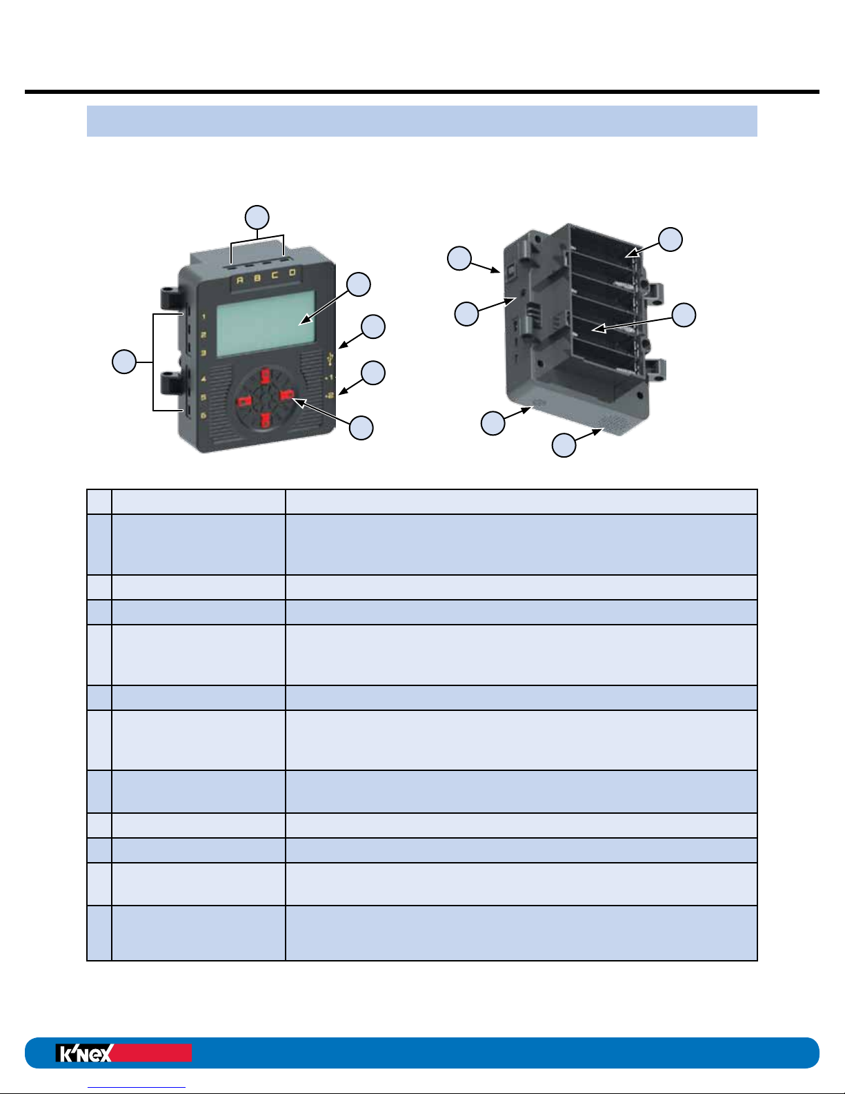
The K’NEX ROBOTICS CONTROL BOX
The K’NEX Robotics Control Box is the link between the computer and the electrical
components in a model. It provides power for the electrical components and also acts
as a buffer between the components and the computer. It can store and play up to 10
different programs.
A
K
C
G
E
B
F
H
D
The K’NEX Robotics Control Box is equipped with:
A
4 Motor Outputs
B
6 Sensor Inputs
C
Power Switch
D
Power Supply Socket
E
USB Port
F
2 Digital Outputs
To precisely control motor speed and direction.
To provide feedback and input to the Control Box. The sensors
may be digital on/off switches (such as push button) or analog
measurements (such as distance sensor).
To turn the Control Box on and off.
To power the Control Box via the provided power supply.
To connect the Control Box to a PC via a standard USB cable.
Allows the PC to operate the Control Box directly or download
programs for later use.
To operate LEDs.
L
J
I
G
LCD Screen
H
4 Buttons
I
Speaker
J
Microphone
K
Battery Compartment
Wi-Fi Compartment
L
(behind battery
compartment)
The K’NEX Robotics Control Box has the ability to recognize what is connected to it.
For example, if you connect a motor to port A and another to port D, it will recognize that
motors have been connected. The same is true for remote sensors and digital outputs.
®
Education
To display a list of programs and user options. Can also be
used to display user generated images when running a
program.
To navigate user options and select and run programs
downloaded to the Control Box.
To play sounds.
To detect sound levels.
To house 6 “AA” batteries used to power models when not
connected to the power supply.
(Optional) To house Wi-Fi module. When installed, Wi-Fi
module allows wireless connection to the PC. (sold separately)
3
Page 4
Education
®
Education
®
K’NEX Robotics User’s Guide
HARDWARE
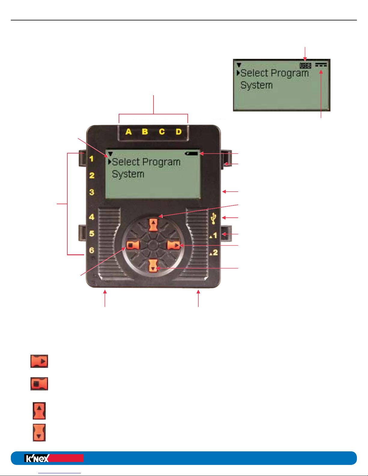
The K’NEX ROBOTICS
USB Plugged In
CONTROL BOX
LCD Screen
Inputs 1 - 6
for Sensors
STOP or BACK
Button
Speaker
Outputs A - D for Motors
Power Supply
Plugged In
Battery Power Level Indicator
Power Switch
Power Supply Socket
SCROLL Up Button
USB Port
Digital Outputs 1 and 2
ENTER or SELECT Button
SCROLL Down Button
Microphone
K’NEX ROBOTICS CONTROL BOX BUTTONS
The ENTER button is used to start programs, progress to the next screen,
or confirm a choice.
The square STOP button is used to stop programs from running (press and hold)
or return to the previous screen.
The SCROLL buttons are used to scroll through menus on the LCD screen.
4
Page 5
K’NEX Robotics User’s Guide
Education
®
Education
®
HARDWARE
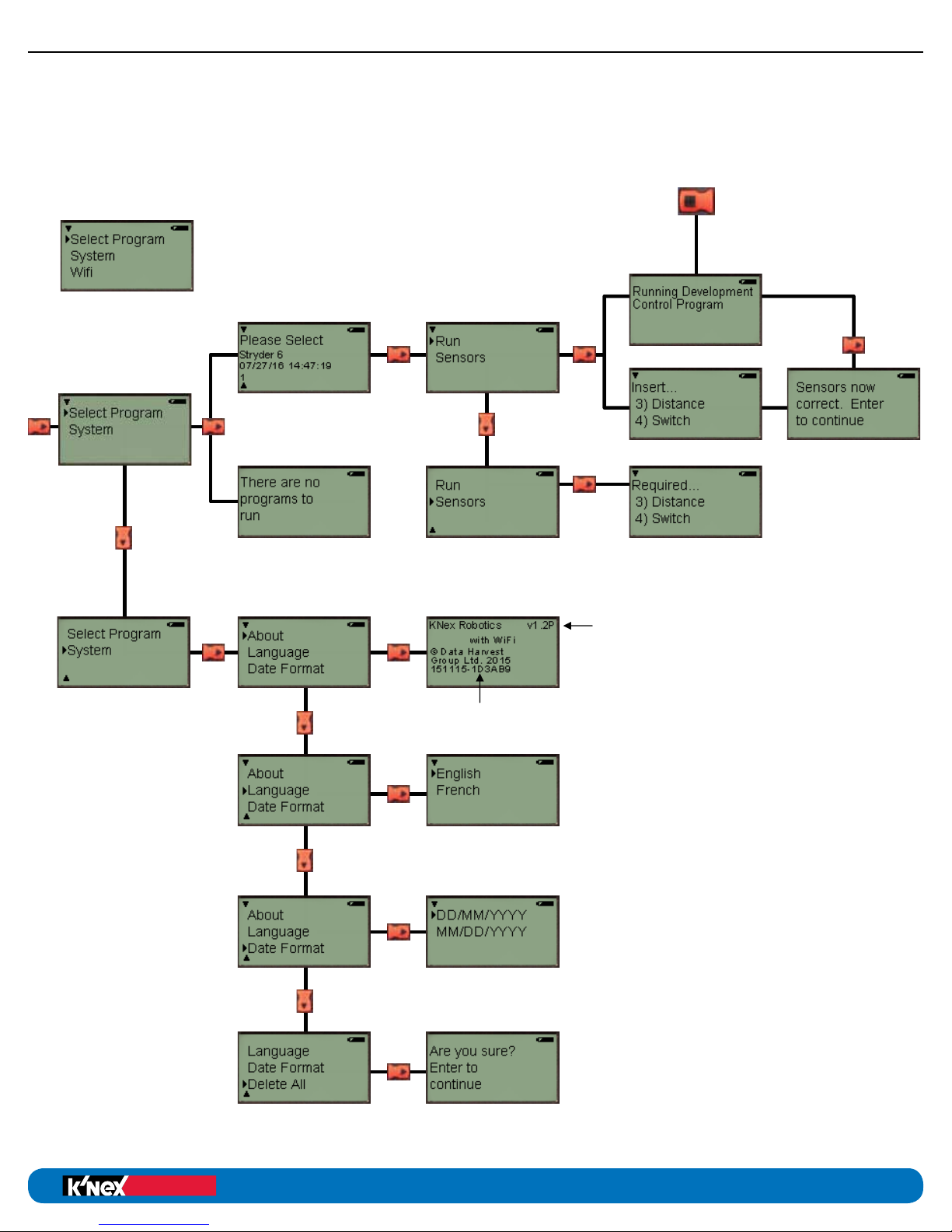
K’NEX ROBOTICS CONTROL BOX
SCREEN NAVIGATION GUIDE
Optional Wi-Fi screen
Wi-Fi screens start
on next page
Press and Hold to Stop Program
Sensors needed for program to run
will disappear upon insertion
Firmware Version Number
See pages 6 and 7 for Wi-Fi
Navigation Screens
Serial Number
5
Page 6
Education
®
Education
®
K’NEX Robotics User’s Guide
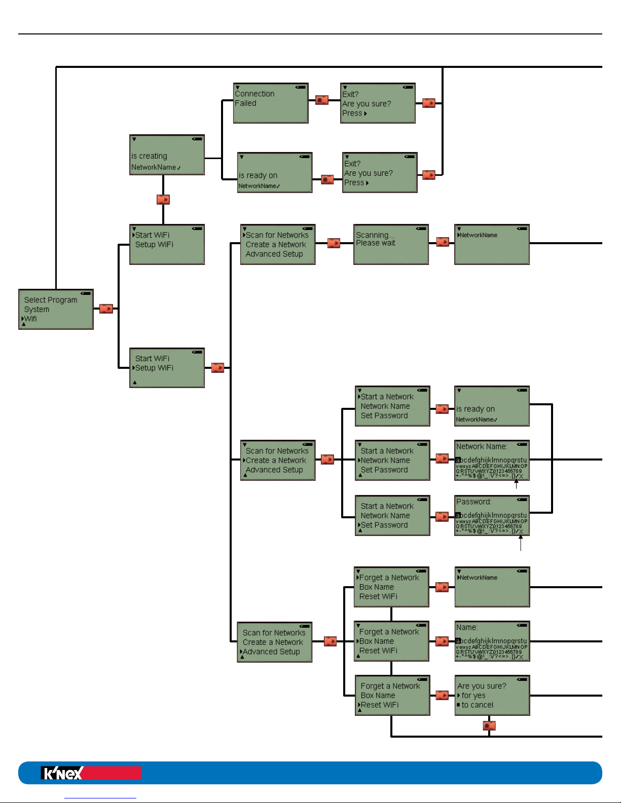
HARDWARE
Chart continues
on next page
K’NEX ROBOTICS
WI-FI SCREEN
NAVIGATION
GUIDE
(If equipped with
optional Wi-Fi)
exit and save
exit without saving
6
Page 7
K’NEX Robotics User’s Guide
Education
®
Education
®
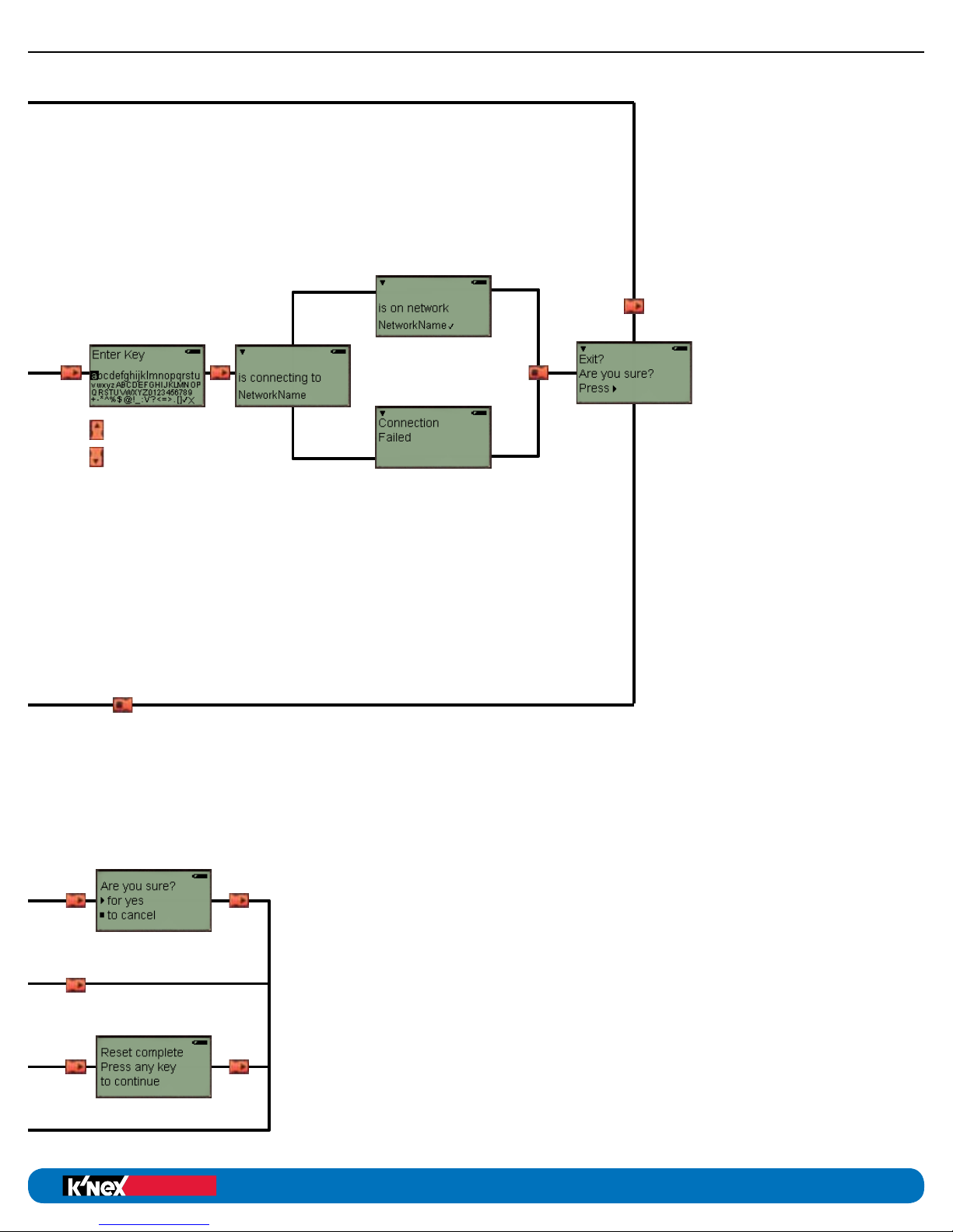
HARDWARE
Move forward and back
through characters
7
Page 8
MOTORS
Education
®
Education
®
K’NEX Robotics User’s Guide
HARDWARE
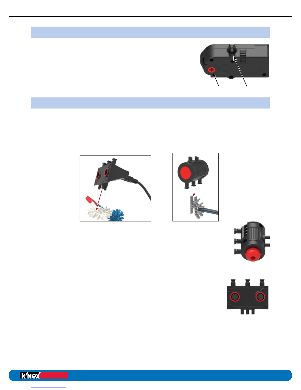
Motors provide motion to models and contain a rotation sensor
that allows precise control of the motor. Motors can be built into
K’NEX models using the Power Take Off (PTO) Drive and rod
loop on the motor housing. Connect motors only to sockets A,
B, C or D along the top of the Control Box.
Commands in the K’NEX Robotics software can be used to control
the speed and direction for each motor. Motors can be operated
for a set number of seconds or a precise number of rotations.
PTO Drive Rod Loop
SENSORS
Sensors provide feedback to the Control Box to allow it to interact with its environment.
Five different types of sensors are provided including 3 remote sensors and 2 sensors that
are part of the Control Box.
The sensors and LED can each be assembled to a K’NEX model two ways; either by snapping
the squared rod ends into a K’NEX connector or pressing the pins on the other side of the
housing into the side openings of a K’NEX connector.
Touch Sensor
A simple push button switch is one type of touch sensor. When the button is
pressed (input ON) the contacts connect together and allow current to flow.
When the button is released (input OFF) the contacts are open and no current
flows.
Distance Sensor
This sensor uses ultrasonic pulses to measure distance between the sensor
and an object. The sensor has two components; an emitter and receiver.
The emitter sends out an ultrasonic pulse which bounces off the object
in front of it and is echoed back to the receiver. The receiver picks up the
“echo” and calculates the distance between the sensor and the object
based on how long it took for the pulse to travel from the sensor to the
object and back. This same technology is used in rear parking systems in
many modern cars and is very similar to echo location used by dolphins.
The Distance Sensor will work best when detecting large, hard, flat surfaces. Small or curved
surfaces, surfaces with many holes, and thin surfaces may not work properly with the sensor.
Multiple distance sensors operated near each other may interfere with each other and cause
incorrect readings.
8
Page 9
K’NEX Robotics User’s Guide
Education
®
Education
®
HARDWARE
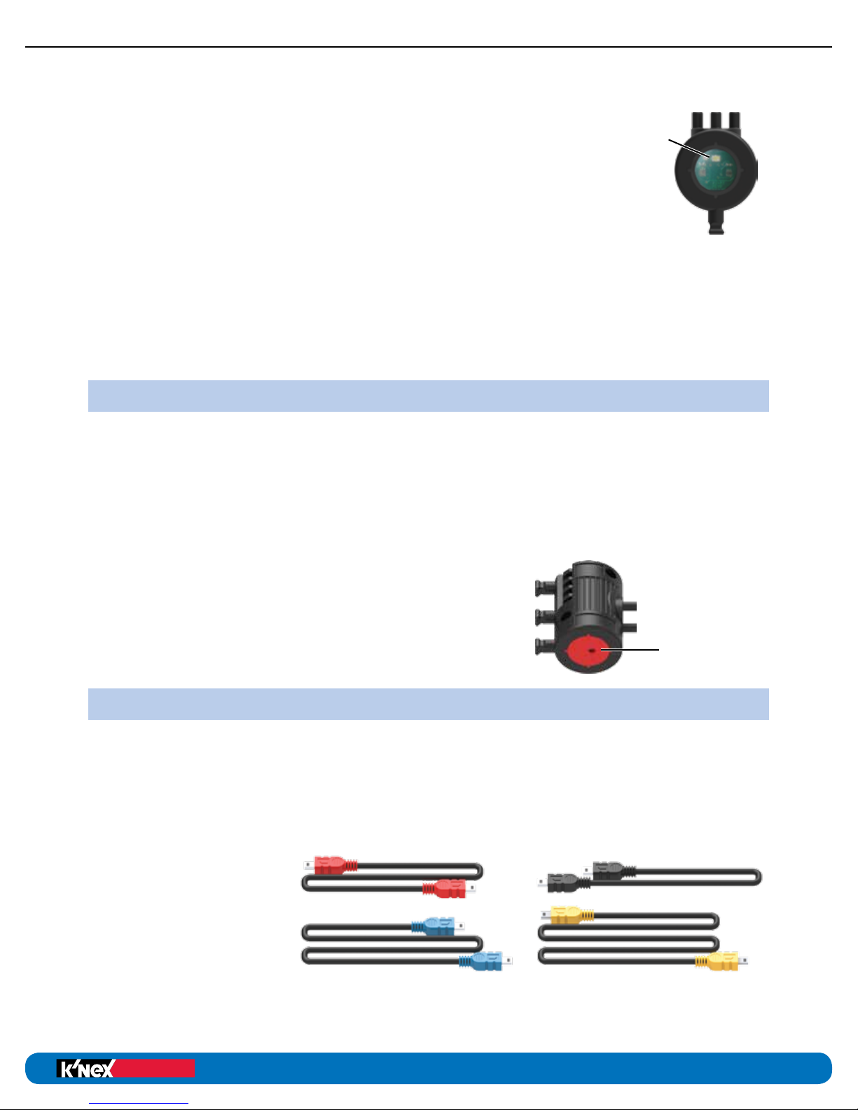
Color/Light Sensor
This is a dual use sensor which is capable of measuring either light levels
or the color of an object. The sensor contains two separate sensor chips
and a white LED which are visible behind the clear window on the end
of the housing.
When used to measure light, the sensor will return values between 0%
(dark or black) and 100% (light or white). Either sensor 1 or sensor 2 can
be selected to measure light values independently. Additionally, a “light
difference” option is available to measure the absolute difference between
sensor 1 and sensor 2.
When used to measure color, the sensor will identify one of 6 color values: red, orange,
yellow, green, blue or violet. When measuring color, only sensor 1 is used.
Microphone
This sensor is built into the Control Box and can only be used to measure sound levels.
OUTPUTS
Three different types of outputs are provided, two contained in the Control Box and one
remote.
WHITE
LED
1
2
LCD (Liquid Crystal Display)
The monochrome LCD is built into the front of the Control Box. When the power is switched
on, the display shows a welcome screen and then defaults to the main menu, which displays
program and user options. The LCD can also be programmed to display text, variables or
user generated graphics.
Speaker
The 8khz mono, speaker is built into the bottom of the
Control Box and can be used to playback short sounds.
L.E.D. (Light Emitting Diode)
LED
The LED has four output states: Off, Red, Green or Yellow.
CABLES
Four different cable lengths are provided for connecting the motors and sensors to the
Control Box. Each cable length has a uniquely colored plug end for easy identification;
9” black, 13” red, 17” blue, and 21” yellow.
Only the provided cables should be used to connect components to the Control Box.
DO NOT attempt to connect the Control Box to any device or component other than those
provided by K’NEX. Doing so could damage the component, the Control Box or both and
void all warranties.
A standard USB to mini
USB cable is provided
for connecting the Control
Box to a PC.
9
Page 10
POWER SUPPLY
Education
®
Education
®
K’NEX Robotics User’s Guide
HARDWARE
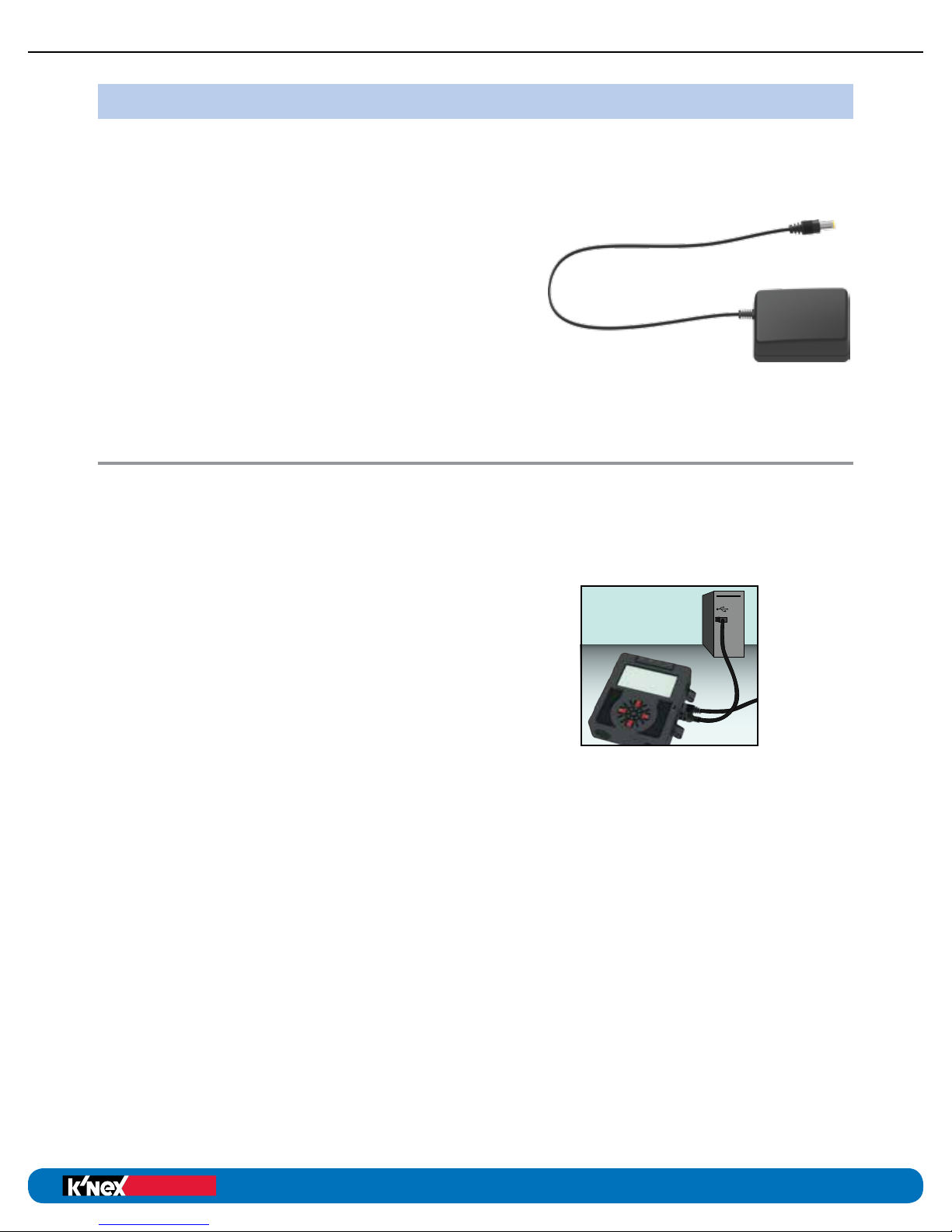
The power supply “transforms” the AC power from your household electrical outlet into
DC power similar to that supplied by batteries. The power supply can be used to power
the Control Box to conserve battery power. It is recommended that it be used to power the
Control box when creating and testing control programs.
The power supply can be used at any time, either
with or without batteries installed in the Control Box.
The power supply cannot be used to charge batteries,
as internal electronics prevent it from doing so.
DO NOT connect the Control Box to a power supply
except the one supplied by K’NEX. Doing so could
damage your unit and void the warranty. Please contact
K’NEX for a replacement if your power supply becomes damaged or is lost.
Setting Up for the First Time
The K’NEX Robotics Control Box is the link between the computer and the electrical
components on a model. It provides power for the electrical components and also acts
as a buffer between the components and the computer. In order to use a computer to
control these components, you will need to download the K’NEX Robotics software.
You will need:
• A PC (not Mac compatible) with an available
USB port
• The K’NEX Robotics software (supplied at
www.knex.com/robotics)
• The K’NEX Robotics Control Box (supplied)
• A USB connection cable (supplied)
• The power supply (supplied)
• Input and Output devices such as motors, LEDs,
and various sensors (supplied)
Step 1
Install the K’NEX Robotics software on your computer. For additional details of how to install
and use the software, please refer to the software portion of this user guide.
Step 2
Connect the power supply lead to the socket on the side of Control Box and plug the power
supply into a standard wall socket. Switch the Control Box on and the LCD will display the
welcome screen and other information.
Step 3
The first time a Control Box is connected to the USB port on a computer, the USB drivers will
be installed by the computer.
• Connect the Control Box to the USB port on your computer with the USB cable.
• Windows will automatically detect a new device and install the necessary drivers.
A notification window will pop up in the taskbar along the bottom of your screen to
confirm the driver status.
10
Page 11
K’NEX Robotics User’s Guide
Education
®
Education
®
HARDWARE
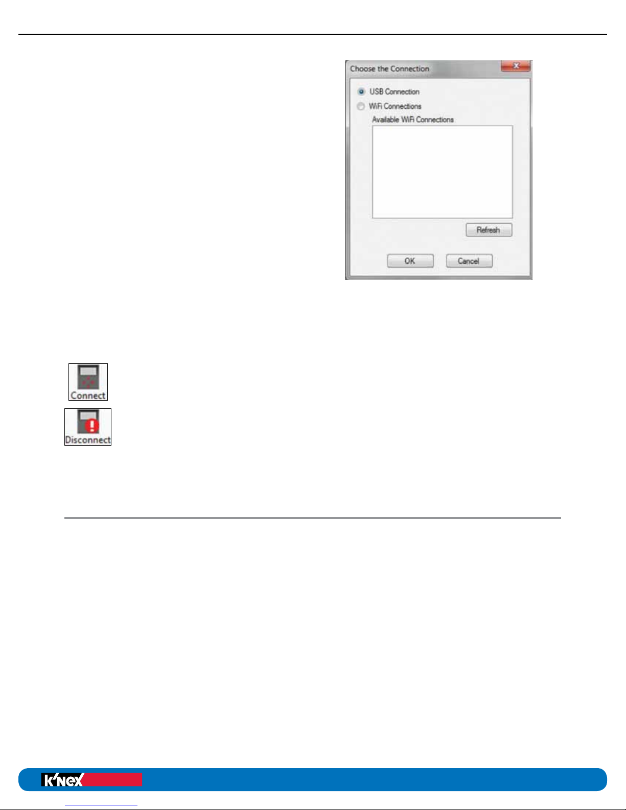
Step 4
To use the Control Box with K’NEX Robotics
software, it must first be set up from the
software.
1. Start the K’NEX Robotics software.
2. If this is the first time K’NEX Robotics
software is opened then a “Choose the
Connection” window will automatically
open immediately after the software
welcome screen.
3. Select “USB connection”.
4. Click on OK. These settings will be saved
and automatically used next time the
program is loaded.
NOTE: No attempt is made to connect to the
Control Box until you click on the ‘Connect’
control box icon from the software menu bar. If you are planning to use the
optional Wi-Fi module to connect to the Control Box, please see the documentation
accompanying the Wi-Fi module for how to set up the connection.
Step 5
Click on the Connect control box icon to establish connection to the Control Box.
When a connection is established the icon changes to show “Disconnect”,
which is used to break off connection with the Control Box.
Using the K’NEX Robotics Control Box
After the Initial Set-Up
• Connect the Control Box to the power supply and switch the Control Box on.
It is possible to connect the Control Box to the computer using only battery power,
but we recommend using the power supply to conserve battery power for operation
away from the computer.
• Connect the Control Box to the computer using the USB cable.
• Start the K’NEX Robotics software.
• Click on the Connect icon to establish a connection between the software and the
Control Box.
When a connection is established the icon will change to Disconnect (which is used to break
off connection with the Control Box).
11
Page 12
There are two distinct modes of operating the Control Box.
Education
®
Education
®
K’NEX Robotics User’s Guide
HARDWARE
1. It can be connected to the computer and operate as an ordinary real time control
interface with the K’NEX Robotics software, providing real time feedback on the
program’s status.
2. It can run a downloaded program while disconnected from the computer.
The program is stored and processed by a microprocessor in the Control Box.
Programs are stored in non-volatile memory in the Control Box so even if the power is
disconnected or turned off, the programs will not be lost. When the power has been
restored, select the desired program using the LCD menus and press “RUN”.
Running a Program When Connected
to the Computer
It is recommended to create control programs with the Control Box (and K’NEX model)
connected to the computer. As you write the control program you can test the functionality
of the model to ensure it works as intended. With the Control Box connected to the computer
and a control program is open, click the “Start/Stop” Icon. The program will play
directly to the Control Box. As the program plays you can watch it progress
through each icon on the screen and in the map tab in the information panel.
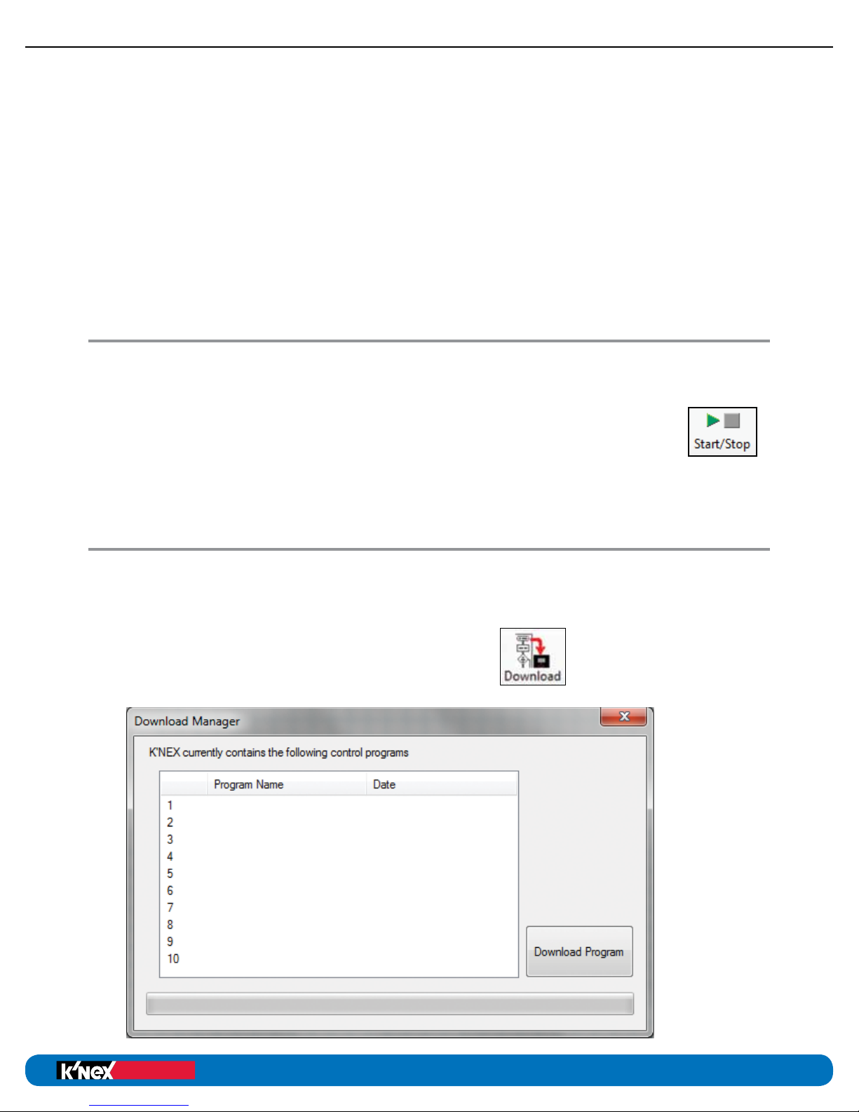
Downloading a Program to the
K’NEX Robotics Control Box
Use the K’NEX Robotics software to write your control program – for more details see the
software portion of this user’s guide. Once the control program has been written, it can be
downloaded to the Control Box as follows:
• Check that the Control Box is connected to
the PC and powered up.
• Select the “Download” icon from the toolbar.
• A “Download Manager” window will open.
12
Page 13
K’NEX Robotics User’s Guide
Education
®
Education
®
HARDWARE
• Select the desired slot for your program by clicking on a number 1-10. The chosen row
will highlight. NOTE: You can choose a vacant spot or overwrite an existing program.
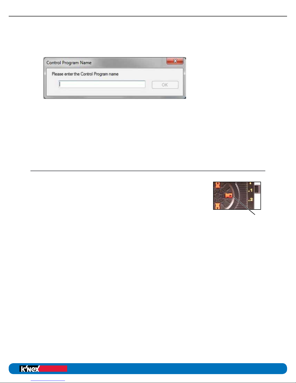
• Click “Download Program” and a “Control Program Name” window will open.
Enter a name for your program (15 characters or less) and click “OK”.
• The “Control Program Name” window will close and the entered program name
will show in the “Compile and Download” window along with the date and time
the program was stored.
• Your program is now stored in the Control Box. Close the “Compile and Download”
window.
Running the Program when
Disconnected from the Computer
• Switch the power to the Control Box on.
• Using the LCD and buttons on the Control Box, navigate to the
desired program and press the “ ENTER” or “SELECT” button.
o If the sensors and motors match the control program, the
program will run. If there are no user programmed graphics
being displayed, the LCD will display “running development
control program”
o If there is a mismatch between the sensors and motors connected to
the Control Box and those called for in the program, the Control Box
will prompt you to connect or “insert” the proper motors and sensors.
For example: “Insert… 3) Distance” means to connect the distance sensor to
port 3. As you make the proper connections the missing item will disappear from
the prompts. Once you make all connections, the box will display “Sensors now
correct. Enter to continue” Press the “Select” button again to start the program.
• To stop a program that is running, press and hold the “STOP” button until the
program stops. The LCD will display “Control program stopped”
• Press “STOP” again to return to the main menu to select and run another program.
o If no user programmed graphics are being displayed, the LCD will display
“program running”.
s
ENTER/
SELECT
13
Page 14

Education
®
K’NEX Robotics User’s Guide
Stored Program Limits
The K’NEX Robotics Control Box has 2Mb of user program storage space.
• Ten programs can be stored in the Control Box.
• The maximum size of any single program is 64K (approximately
6500 symbols or steps!).
• Within each program there can be a maximum of 16 threads (starts)
and an unlimited number of sub-procedures (with up to 14 nesting levels).
• Each program can use up to 64 variables.
• Each program can use an unlimited number of sound samples (up to
a maximum combined duration of 30s).
• Each program can use up to 32 images.
Technical Specifications
• USB V 1.1, V2.0 & V3.0 full speed compatible.
• Power supply, Output 7.5V, 2 A, regulated dc with a positive center and negative
outer pin.
• 6 sensor inputs.
• 4 motor outputs.
• 2 digital outputs.
• 1 speaker.
• 1 microphone.
• Suitable for use in a 32-104 degrees F (0-40C) operating range and 0-95% relative
humidity (non-condensing).
HARDWARE
Please note:
• The Control Box does not contain user serviceable parts.
• Using the Control Box in a way that is outside its normal operation (as described
in this manual) may impair the unit’s (warranty) protection and ability to function
correctly.
®
Education
14
Page 15

K’NEX Robotics User’s Guide
Education
®
Education
®
HARDWARE
TROUBLESHOOTING
Problem:
When I click on the Connect icon, I get a “Communications Error: could not connect to the
interface” message.
1. Disconnect the power supply, reconnect and try again.
2. Check that the Control Box is powered and switched on.
3. Confirm that the USB cable is firmly connected to the USB port on the Control Box
and the USB port on the computer.
4. Confirm that the Interface/Connection is correct. (Select Interface from the File menu.)
If it still fails to respond, contact the Technical Support department at K’NEX.
Please provide the following details:
• The computer platform it is being used with (Windows 7, 8, etc.).
• The software and its version number (from the “Help” and “about” menu).
• A description of the problem being encountered.
If possible, telephone from a location where you can operate the Control Box and the
computer with K’NEX Robotics software installed.
Problem:
I have switched an output on but the component plugged into the output is not working.
Check:
• The component is plugged into the correct port.
• The “Connect” icon in the K’NEX Robotics software shows as “Disconnect”.
• The Control Box is powered and switched on.
• There is not a loose connection.
• The I/O (Input/Output) Panel in the software indicates the output is switched on.
15
Page 16

Education
®
K’NEX ROBOTICS
SOFTWARE GUIDE
Overview
The K’NEX Robotics software is a fully featured Control program. Designed for students 10+,
it offers a simple yet powerful programming language that allows students to program and
control K’NEX models and devices using the K’NEX Robotics interface.
The language is based on worldwide standard flowcharting principals. Flowcharts offer a
high level visual development environment, being both easy to understand and powerful;
students can quickly achieve dramatic, positive and valid results.
In addition to the standard flowchart language, the software offers a side-by-side view of the
program as a traditional textually described program. This high level textual representation
uses everyday language and avoids the risk of errors caused by complex syntax and typing
entry errors. Offering both graphical and language views gives the student the best of both
worlds!
Students are used to highly animated, highly visual stimuli (video games, TV, etc.).
We need to engage the students by matching their expectations within an educational
context:
• to a control project that helps the student to understand a problem.
• that the student can identify with, be it from rsthand experience or via a subject
area they are interested in.
The K’NEX Robotics set offers familiar and exciting models to engage the students.
The Software
The K’NEX Robotics software can be downloaded from www.knex.com/robotics and is
designed to be installed on a single PC or a network of PCs.
Example control programs
The example control programs required to control 6 of the models in the K’NEX Robotics
set are supplied at www.knex.com/robotics. They are not copied to the PC when the
software is installed. If you wish to access these files you need to download them from
www.knex.com/robotics.
Operating Modes
Simulation – The K’NEX Robotics software can run a student’s program without being
connected to the K’NEX Robotics Interface.
Real-time – The K’NEX Robotics software can control the K’NEX Robotics
interface directly. Click on the ‘Connect’ icon for communication to be
established.
Remote – The K’NEX Robotics interfaces allows a control program to be downloaded
from the software into the interface to be run disconnected from the computer.
®
Education
16
Page 17
K’NEX Robotics User’s Guide
Education
®
Education
®
SOFTWARE
System Requirements
Computer:
Operating System:
Minimum Software:
Display:
* If Microsoft.NET 4.0 framework is not detected during the installation setup
process, it will be automatically installed prior to the application install.
This may extend the installation time significantly.
PC with free USB port (not Mac compatible)
Windows 7, 8.1, 10
Microsoft.NET 4.0 Framework
1024 x 768
Installing the K’NEX Robotics Software
• Log on as ADMINISTRATOR (or with equivalent access rights) on the system.
• Close any open programs – you need to restart your machine after installation
for configuration changes to be made.
• The K’NEX Robotics software can be downloaded from www.knex.com/robotics.
After downloading the software, navigate to the location the files were downloaded
and click on setup.exe.
• Follow the on-screen instructions to complete the installation of the software and
its associated files.
• When the installation is complete, restart your system.
Connecting the K’NEX
Robotics Interface
USB connection
The first time the K’NEX Robotics interface is connected to a USB port on the computer,
the USB drivers will need to be installed.
1. Install batteries into the K’NEX Robotics interface or plug it into the provided
power supply and turn it on.
2. Connect the K’NEX Robotics interface to a USB port on the computer with the
provided USB cable.
3. Windows will automatically detect a new device and install the necessary drivers.
Starting the K’NEX Robotics Software
for the First Time
Start the K’NEX Robotics software by selecting it from the start menu.
17
Page 18
Education
®
Education
®
K’NEX Robotics User’s Guide
SOFTWARE
Menu Bar
Standard Toolbar
Selector Toolbar
Symbol
Toolbar
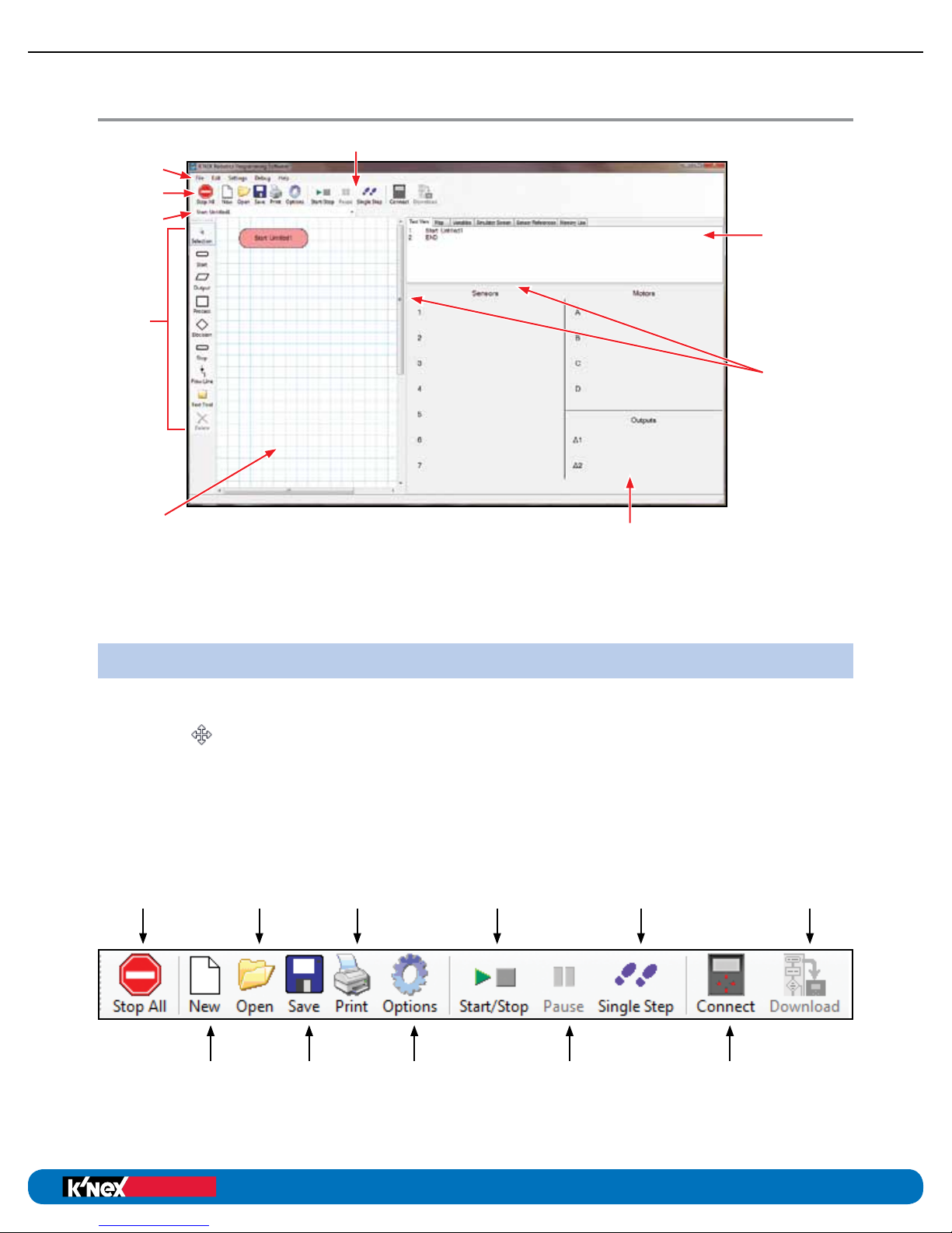
The Screen Layout
Control Toolbar
Information Panel –
This panel contains
6 different tabs that
display different
information about the
control program.
Window Dividers –
drag left/right or
up/down to alter
window size/shape.
Edit Area – This is where the
flowchart or procedure currently
being created, edited or reviewed
is displayed. Right click to alter
the scale of view.
Toolbars
The toolbars can be positioned at the top, bottom or left of the window. To move a toolbar,
position the mouse pointer over the dotted line at the left end of the toolbar. When it
becomes a
The Standard Toolbar
Stop All:
Stop all
programs or
procedures
symbol, click, hold down and drag the toolbar to the desired position.
Open:
Open an
existing
program
I/O Panel or the Selection Panel
• The I/O tab displays the state of all the inputs/ouputs/motors and sensors.
• If a symbol is currently selected then this area becomes the selection panel.
Print:
Print the
current
program
- contains
several
formatting
options
Start/Stop:
Start or stop
a program
Single Step:
Run through
a program
one step at
a time
Download:
Download
a program
to a control
box
New:
Create a
new control
program
Save:
Save the
current
program
Options:
Modify
system
settings
Pause:
Temporarily
halt the
running
program
Connect:
Connect to
a control
box
18
Page 19

K’NEX Robotics User’s Guide
Education
®
Education
®
SOFTWARE
The Flowchart or Procedure Selector Toolbar
Use the drop-down menu in this toolbar to select which “Start” or “Procedure” will be
displayed in the editing area.
The Symbol Toolbar
To create programs you need to place appropriate symbols onto the edit area, enter the
correct control commands into the symbols and then connect the symbols together to
specify the flow of the program.
Selection – this option is used to highlight and modify flowchart symbols. See page 28.
Start – a start symbol is required for the beginning of a flowchart or for a procedure
that will be called up by the main program. See page 29.
Output – use this symbol to operate a motor, play a sound or display graphics or text on
the LCD. See page 30.
Process – use ‘wait’ for the time that an output should be switched on, ‘procedure’ for
the flowchart to call up a procedure or ‘make’ to set up a variable. See page 36.
Decision – used when a question must be asked to decide what to do next.
It will check for feedback from an input (switch or sensor) or the value
of a variable to decide YES – do this or NO – do that. See page 40.
Stop – use to end a owchart or procedure. See page 45.
Flow Line - use to connect symbols together in the order they should operate to create
the flowchart. See page 46.
Text Tool – use to add labels to a flowchart. See page 46.
Delete – use to delete selected items. See page 47.
19
Page 20

Information Panel
Education
®
Education
®
K’NEX Robotics User’s Guide
SOFTWARE
The Text View Tab
The Text View tab displays the flowchart or procedure that is in edit area in a textual format.
The text will be in red italics until the flow line is correctly set, i.e. a flow line connects the
symbols.
Right click in the area to alter the font size.
If you click on a line in text view, it will highlight the appropriate symbol in the edit area and
vice versa.
20
Page 21

K’NEX Robotics User’s Guide
Education
®
Education
®
SOFTWARE
The Map Tab
The Map Tab displays the complete control program with all starts and procedures.
Right click in the map area to alter the scale of view. When a control program is
running, the symbols will highlight as they become active when this tab is selected.
If you click on a “Start” or “Procedure” in the map view, it will become active in the edit area.
The Variables Tab
Clicking this tab displays a list of variables and their numerical value. Several variables
are provided by default, but additional variables can be created in the process symbols.
21
Page 22

The Simulator Screen Tab
Education
®
Education
®
K’NEX Robotics User’s Guide
SOFTWARE
This tab displays images included in a program that are displayed on the LCD.
Images will appear in this tab as they are called for in a program. If no images
are called for in a program, this tab will remain blank.
The Sensor References Tab
This tab will display all sensor, motor and LED connections required by the active
flowchart. Consult this tab to confirm your model has the proper connections if
you get a “The connected sensors do not match required” error when trying to
run a program on the Control Box.
22
Page 23

K’NEX Robotics User’s Guide
Education
®
Education
®
SOFTWARE
The Memory Use Tab
This tab displays information about the available space for sound and image files. As you
load sounds and images to a control program, this tab will inform you how much of the
available space you have used. A total of 30 seconds of sound and 32 different screen
images can be stored for each control program. If you accidentally load too much sound or
too many images, a red warning will pop up in this window to alert you of the overrun. If this
happens simply delete the output box you just created to remove the excess sound or image.
Input/Output (I/O) Panel
NOTE: If a symbol is currently selected in the edit area, then this panel is replaced by the
selection panel. To make the I/O panel visible again, click on a blank space in the edit area.
This area displays the current status of the sensors, motors and digital outputs in the control
program. Icons representing I/O components connected to a Control Box will populate this
panel when the Control Box has been connected to the computer. The current reading values
will be displayed for each sensor or motor when a Control Box is connected. Only sensors
and motors that are visible in the panel are available to use in the flowchart symbols.
To make a sensor or motor available for a control program when no Control Box is
connected, simply click on the sensor, motor or output number until the desired sensor
icon shows. Once the icons are visible these I/O components can be written into a program.
NOTE: If the interface is connected then the control of an input or the value of a sensor
is taken over by the input/sensor connected to the Control Interface.
23
Page 24

Program Terminology
Education
®
Education
®
K’NEX Robotics User’s Guide
SOFTWARE
A computer controlled system needs a sequence of commands, this is called a program.
The program should give commands in the correct order to tell the computer exactly what
to do and when to do it.
The Control Program is the entire set of commands. There is only one control
program. It can be made up of one or more flowcharts.
A Flowchart – each flowchart begins with a Start. There can be up to 16 flowcharts
or Starts in a control program.
A Procedure – a procedure is a subset of a flowchart. It will not run on its own,
it must be called up by a flowchart. The number of procedures is limited by program
memory but there can only be 14 nested levels as mentioned on page 14.
Placing Symbols and Entering
Commands
• Click on the symbol you require in the symbol toolbar (it will highlight to show it
has been selected).
• Move the mouse over into the edit area (the selected symbol will be locked to the
cursor), when the symbol is in the correct location, click to place it.
NOTE: Flowcharts usually run from the top left of the screen downwards, and if
required, over to the right.
• Once the symbol has been placed in the edit area, the I/O panel will change to
a selection panel from which you choose the action required. Depending on the
symbol placed, the selection panel will offer different options.
24
Page 25

K’NEX Robotics User’s Guide
Education
®
Education
®
SOFTWARE
For example:
When you place an Output symbol, the selection panel will look like this:
:
25
Page 26

To switch on motor A, click a direction for the motor to turn and enter a motor speed
Education
®
Education
®
K’NEX Robotics User’s Guide
SOFTWARE
between 0 and 100%. You can use the mouse to click numbers and symbols from the
keypad in the selection window, or you can type numbers using the standard keyboard.
When you have made your selection, click on the OK button to save your changes and
the commands will appear in the symbol in the edit area. The text for the program will
also appear in the text view tab.
Although the selection panel changes according to which symbol is selected, it always
follows a similar format:
The command is built up by clicking on buttons. As the command is built up, the selected
choices are displayed in the text line at the top of the selection panel.
With some panels there is an option to enter data using the keyboard (i.e. when manipulating
variables or entering values).
To delete a symbol – if the Selection tool isn’t already active, click to select. Click on the
symbol (it will highlight to show it is selected) and click on the Delete icon.
26
Page 27

K’NEX Robotics User’s Guide
Education
®
Education
®
SOFTWARE
Connecting the Symbols
The next stage is to connect the symbols in the edit area together to show the order in which
each symbol (command) should be carried out (the direction of the flowchart):
1
2
3
1. Click on the Flow Line icon (1).
2. Click on the first symbol (2)
(usually Start), a blue dot will
mark the connect point.
3. Click on the symbol next in the
sequence (3). The program will
automatically draw the flow line
between them (it will try to avoid
other symbols and lines where
possible).
Flow lines cannot be repositioned
manually and only reposition when
symbols are added, deleted or
moved.
4. Repeat this process until all of the
symbols are connected.
To deselect the Flow Line tool: either
click back on the Flow Line icon or
click another icon.
Flow Lines from a Decision Symbol
A Decision symbol has 2 flow lines, a YES and a NO line. The first line that will be drawn is
from the base of the decision symbol. The line from the base of the symbol is normally the
YES line, the line from the right is the NO line. To flip the position of YES and NO, make sure
the Selection tool is active, and double click on the decision symbol.
Double click
to flip
27
Page 28

Deleting Flow Lines
Education
®
Education
®
K’NEX Robotics User’s Guide
SOFTWARE
If you make a mistake and wish to connect a line with a different symbol either:
• Use the Flow Line tool as if there wasn’t already a line there, i.e. by placing a new
line from one symbol to another to automatically replace the old connection.
OR
• Select the line you wish to change and click on the Delete icon. Then select the ow
line symbol again and make the desired connection.
NOTE: If a flowchart is run and it reaches a symbol that does not have a flow line to dictate
where to go next, the flowchart will cease to run. Therefore it is important that all symbols
are connected.
The Symbols
Selection
This tool allows you to select an existing symbol in the edit area. Once selected it can be
moved, edited, deleted, etc.
NOTE: This tool will automatically deselect when Flow Line is selected.
To select a symbol
mputer:
To deselect
ystem:
Click on the symbol (it will highlight to show it is
selected).
Click in the blank space in the edit area.
To select more
than one symbol
in the edit
Software:
area
With Selection active, hold down the CTRL key
and click on each symbol.
Position the mouse pointer at the top corner of
To select part of
a flowchart
the area to be selected. Click, hold down and
drag the rectangular box over the area to be selected and release the mouse.
To move a symbol
To edit the
commands in
a symbol
To delete a symbol
or line
Click on the symbol (it will highlight to show it is
selected) and drag to a new position.
Click on the symbol (it will highlight to show it
is selected). Change your current choice in the
selection panel.
Click on the symbol or line (it will highlight to
show it is selected) and click on the Delete icon.
28
Page 29

K’NEX Robotics User’s Guide
Education
®
Education
®
SOFTWARE
The Start Symbol
NOTE: The edit area will only show the flowchart (Start) or procedure (Procedure) that
is currently being edited. Therefore when a new Start symbol is selected, any existing
flowchart or procedure will disappear from the edit area.
• When the software is opened or New is selected, a Start symbol is automatically
placed in the edit area.
• Click on the Start symbol in the selection panel then click on either the Start or
a Procedure button. If you enter a name in the start tab, a new start is created.
If you enter a name in the Procedure tab, a new procedure is created.
• Type in a name and click on OK.
• To begin a new owchart or procedure click on the Start icon, a new Start symbol will
automatically be placed in the edit area.
• To edit – click on the Start symbol (it will highlight to show it is selected). Alter the
current choice in the selection panel. To erase a name, highlight the name and then
select delete on your keyboard.
NOTE: If you delete a Start symbol, you will delete the entire flowchart or procedure that
uses the symbol.
Start (Flowchart)
Selecting a Start symbol will create a new flowchart. Whenever a control program is ‘run’
this start will be processed and will run alongside any other ‘starts’ that have been created.
Multiple starts are a very simple yet powerful way to offer multi-tasking (or multi-threading)
features to a program.
29
Page 30

For example: A control program written to operate a machine could have one flowchart
Education
®
Education
®
K’NEX Robotics User’s Guide
SOFTWARE
which actually operates the machine while a second flowchart could continually look to
ensure that the safety cut-off switch has not been pressed. If the switch is pressed, this
flowchart could stop the whole program from running. By splitting a ‘safety check’ into
a separate flowchart, the switch can be constantly checked, and will therefore be highly
responsive. It also prevents students having to add lots of checks into the flowchart that
operates the machine.
Procedure
Selecting the Procedure tab and entering a name will create a new procedure. A procedure
is a subset of a flowchart and cannot be run on its own. A procedure allows specific parts of
a flowchart to be programmed in isolation. The flowchart can then ‘call up’ these procedures
and repeat as required. All procedures must end in a stop command. See page 49 for more
details.
The Output Symbol
• Click on the Output icon, move the mouse into the edit area and click to x it in place.
• In the selection panel click on the Motor, Output, Sound, Image or Text tab.
• Make your selection from the panel and enter the desired parameters.
• Click on OK to enter the completed command into the output symbol.
NOTE: You must click OK at the bottom of the selection window to save any changes you
make to your program.
Motor
Motors can be switched Forward (Fwd), Reverse (Rev) or Off.
The speed of a motor can be specified between 0% and 100%. Motor speed can also be
specified using variables.
Click on the Rev, Off or Fwd button in the row of the desired motor and enter the desired
speed.
A motor can be simply switched on, meaning it will stay on until another command tells it to
stop. Alternatively a motor can be switched on for a set time in seconds (s) or set number of
revolutions (Revs).
All four motors can be activated in a single output box, but the duration of activation (infinite,
number of seconds or number of revolutions) will be the same for all motors when using a
single box.
30
Page 31

K’NEX Robotics User’s Guide
Education
®
Education
®
SOFTWARE
During typical behavior the flowchart executes one command and then immediately
proceeds to the next command. However, it can be forced to wait until the motor command
has completed. For example, the motor could be switched on for 3 seconds and the flowchart
forced to stay at this point until the 3 seconds has elapsed by checking the “Wait for motor(s)
to finish” box.
In most cases if you specify a number of seconds or revolutions for a motor to run, you will
want to check the “wait for motor(s) to finish” box for your program to operate properly.
31
Page 32

Output
Education
®
Education
®
K’NEX Robotics User’s Guide
SOFTWARE
Select the output number you wish to use, then click the Off, Green, Red, or Yellow button to
select the output status of the LED.
Both LED outputs can be controlled in one command if desired. Simply make the selections
you want for both before clicking on OK.
To edit: Click on the selected number button to deselect and deactivate that output.
The selection above will turn the LED plugged into output 1 green.
32
Page 33

K’NEX Robotics User’s Guide
Education
®
Education
®
SOFTWARE
Sound
The K’NEX Robotics software can use any sound file in a .wav, .mp3 or .wma file format.
To use a sound, click on the “Read Sound File” button. Locate and select the sound file to
be used. Click “Open“ to load the file. Click the “OK” button in the botton right corner of the
selection panel to save the changes. The sound file name and duration will now appear in
the sound list on the “Memory Use” tab.
To re-use a sound file in the same control program, click the “Use Existing Sound File”
button and select an existing file from the list. After the existing file is chosen, click the
“OK” button to save changes.
Select one of four options for playing the sound:
Start playing
sound
mputer:
Start playing
sound and wait
Start playing
sound and then
repeat
Software:
Stop playing all
sounds
The sound will run until the sound file finishes
or the flowchart hits a stop.
The sound will play completely before the
flowchart moves on to the next step.
The sound file will play entirely and repeat from
the beginning until the flowchart stops running
or the “Stop playing All Sounds” command is
used.
Use this command to stop playing all sound files
that may be playing in your control program.
NOTES:
- Only one sound can be played at a time. If you wish to play multiple sounds in
succession you must use the “start playing sound and wait” option for each sound.
- Each control program is limited to a total of 30 seconds of sound files.
- A sound that is loaded into a control program only counts against the 30 second
sound limit once. You can reuse the same sound as many times as you like in the
control program.
- If you accidentally exceed the 30 second sound limit, simply delete the output icon
containing the last sound uploaded. This will remove the sound from the control program.
33
Page 34

Image
Education
®
Education
®
K’NEX Robotics User’s Guide
SOFTWARE
User generated images can be displayed on the LCD during your program. For best results
use 128x64 pixel black and white BMP files that match the screen resolution. The software
can load and convert most images files (.bmp; .jpg; .tif) for display on the LCD. However,
images that are not 128x64 pixels may become distorted or clipped and color images will be
converted to “black and white”.
.
To use an image, click on the “Read Image File” button. Locate and select the image file to
be used. Click “Open“ to load the file. Click the “OK” button in the bottom right corner of the
selection panel to save the changes. The image file will now be counted in the “Number of
images” total on the “Memory Use” tab.
To re-use an image file in the same control program, click the “Use Existing Image” button.
Select the image from the pop-up list that includes the image title and a picture of the image.
After the existing file is chosen, click the “OK” button in the pop-up window and the “OK”
button in the bottom right corner of the selection window to save changes.
Select one of two options for displaying the image:
Display Image – the image will be displayed until another image or text is displayed or
the flowchart hits a stop.
Clear Image – remove the previous LCD image and return to a blank screen.
NOTES:
- A control program can use up to 32 images.
- An image that is loaded into a control program only counts towards the image total once
and can be re-used over and over.
- If you accidentally exceed the 32 image limit, simply delete the output icon containing the
last image uploaded. This will remove the image from the control program.
34
Page 35

K’NEX Robotics User’s Guide
Education
®
Education
®
SOFTWARE
Text
Up to four lines of text can be displayed on the LCD during your program.
Select the number button that corresponds to the line on which you wish to display text.
Click in the text box next to the line number you have selected and enter the desired text,
approximately 15 characters per line.
Select one of two options for displaying the text:
Display Text – the text on that line will be displayed until another text command
replaces that line, or an image is displayed or the flowchart hits a stop.
Clear Image – remove all lines of text previously specified.
NOTES:
- You can specify 1 line or up to all 4 lines of text in a single output box.
- To clear a single line of text, set a command that leaves the text box blank for that line.
- The position of the text lines is fixed vertically on the LCD. To make text appear near the
center of the LCD, use line 2 or 3 and leave the others blank.
35
Page 36

The Process Symbol
Education
®
Education
®
K’NEX Robotics User’s Guide
SOFTWARE
Click on the Process icon, move the mouse into the edit area and click to fix in place.
In the selection panel, click on either the Wait, Procedure or Make button.
Make your selection from the panel.
Click on OK to enter the completed command into the process symbol.
36
Page 37

K’NEX Robotics User’s Guide
Education
®
Education
®
SOFTWARE
Wait
This delays the flowchart at the current symbol (current flowchart only) for the allotted amount
of time entered. For example, use this to keep an Output LED switched On for 2 seconds.
Enter a time in seconds from the keypad buttons shown using the mouse or type in the value
using the PC keyboard. Variables and simple equations using variables can also be used to
determine the time for the wait.
The smallest increment of time you can use in a wait is 0.1 seconds.
Procedure
This function is used to call up a previously defined procedure. The default is for a procedure
to run once, but you can specify the number of times a procedure repeats by entering a value
in the repeat box.
37
Page 38

NOTE: Additional vertical lines are added to the sides of the symbol
Education
®
Education
®
K’NEX Robotics User’s Guide
SOFTWARE
to distinguish it from a regular process symbol in a flowchart.
Select the procedure’s name from the list of existing procedures or type in a new procedure
name. (If you type a new procedure name you will need to create this procedure later.
Procedures will not be visible in the existing procedures list until they have been created
using a new start in the edit area.)
If required, type in the number of times you would like the procedure to be repeated.
To edit: Select a different procedure. Highlight and delete the repeat number using your
keyboard.
Regular Process Symbol
Procedure Process Symbol
Make
This function allows variables to be defined and altered.
38
Page 39

K’NEX Robotics User’s Guide
Education
®
Education
®
SOFTWARE
• Select the letters, mathematical symbols and numbers from the keypad or type them
in. To edit: Use the ‘C’ key to clear or highlight and delete using your keyboard.
A variable is a letter or word that can be assigned a value.
e.g. Make x = 0 OR Make SwitchCount = 1.
The variable and its value will not ‘exist’ until it is created by the control program being run.
The value of the variable can be observed (once created by the program) in the Variable
panel.
NOTE: If more than one word is used for a variable name, there should be no spaces
between words. Capital letters may be used to help distinguish words as shown in the
example above.
The variables are global, so the value of a variable in one flowchart will be ‘seen’ by all the
other flowcharts and procedures in the control program.
Standard mathematical operators can be used within this function; addition, subtraction,
multiplication and division.
e.g. Make x = x + 5 OR Make x = x / 3 OR Make x = x * 2
NOTE: Variables are stored to 1 decimal place and can be in the range ±107374182.3.
• A variable can be used to store information.
For example: In an Elevator program we could store the current floor in a variable called
‘floor’ by using Make floor =1. This allows us to check later in the program to
see what floor we are on and which direction we have to move in to get the
new floor. (i.e. If we need to go to level 2 and the floor variable tells us we are
currently on 1, then we need to go up!)
• The value of a variable can be checked by a decision symbol (Is Variable x > 5).
For example: If the pushbutton has been pressed 6 times, shut the model off.
• Random can be used to generate a random decimal between 0.000 and 0.999.
A decision symbol can be used to check for a random number.
Seconds
Seconds is a free running timer that starts from zero to give the elapsed time (in seconds)
since a program was started.
39
Page 40

The Decision Symbol
Education
®
Education
®
K’NEX Robotics User’s Guide
SOFTWARE
Click on the Decision icon, move the mouse into the edit area and click to fix in place.
In the selection panel, click on either the Sensor or Variable button.
Make the selection from the panel.
Click on OK to enter the completed command into the decision symbol.
The Decision symbol checks to see if a specified condition is met and decides what to do
next. It has both a YES and a NO line since these are the two options for any condition.
The decision symbol can check the value of a variable, the status of input sensors,
the status of motor and the status of the output LEDs.
The first flow line will connect to the base of the symbol which is “yes” by default.
You can swap the position of yes and no by double clicking on the decision symbol.
40
Page 41

K’NEX Robotics User’s Guide
Education
®
Education
®
SOFTWARE
Variable
NOTE: The command Make (see page 38) is used to generate a variable and assign a value.
Use this option to check the value of a variable.
Enter the condition to be checked for using either the radio buttons or the PC keyboard.
For example:
• Is Counter = 5 Checks to see if the variable “Counter” is 5.
• Is Counter < 99 Checks to see if the variable “Counter” is less than 99.
41
Page 42

Education
®
Education
®
K’NEX Robotics User’s Guide
SOFTWARE
Sensor
Used to check the state of an input, e.g. to check to see if a switch has been turned on.
• Select the desired sensor from the sensor drop down list.
• Enter the condition to be checked for using either the radio buttons or the
PC keyboard.
Distance Sensor
Port 1
Options for
Color/Light Sensor
Port 2
Switch
Port 3
For example:
Is “1 Distance” < 250
• Checks the value of distance sensor plugged into port 1 to see if it is less than 250mm.
Is “3 Switch” = “ON”
• Checks to see if the switch plugged into port 3 is “ON” or pressed.
42
Page 43

K’NEX Robotics User’s Guide
Education
®
Education
®
SOFTWARE
Is Motor
Used to check the state of a motor; either how fast or what direction it is turning.
• Select the desired motor from the motor drop down list.
• Enter the condition to be checked for using either the radio buttons or the
PC keyboard.
To query motor direction use a “1” for forward and a ”–1” for reverse.
For example:
Is “A Motor” = –1
• Checks to see if the motor plugged into port “A” is running in reverse.
Is “A Motor Speed” > 50
• Checks to see if motor A is at more than 50% power.
43
Page 44

Is Output
Education
®
Education
®
K’NEX Robotics User’s Guide
SOFTWARE
Used to check the state of an output; Off, Red, Green or Yellow.
• Select the desired motor from the motor drop down list.
• Enter the condition to be checked for using either the radio buttons or the
PC keyboard.
NOTE: You can select the desired LED color from the radio buttons or use the corresponding
number shown on the button in your command line. For example: “Is 1 Output = Green” is
equivalent to “Is 1 Output = 4”
For example:
1 Output” = “Red”
Is “
• Checks to see if the LED connected to
2 Output” = “4”
Is “
• Checks to see if the LED connected to
1 is red.
2 is green.
44
Page 45

K’NEX Robotics User’s Guide
Education
®
Education
®
SOFTWARE
The Stop Symbol
Click on the Stop icon, move the mouse into the edit area and click to fix in place.
Stop will automatically be selected. If Stop All is required, select the Stop All button in the
selection panel.
Click on OK.
Stop
The Stop command is used to stop a flowchart or a procedure. Depending on where it is
used it will have different effects:
Stop at the end of a flowchart – when the program running encounters this
command it will simply stop running the
flowchart. If there are other flowcharts running
(multi-tasking) they will continue unaffected.
Stop at the end of a procedure – all procedures must have a stop, without one
the program will eventually fail. When the stop
is encountered the procedure will stop running
and return to the place it was called from.
Stop All
This is a special version of the stop command. Whenever this command is encountered it will
stop all procedures and flowcharts immediately, i.e. it will stop the whole control program.
In effect this is like an emergency stop, everything will shut down. It is not a ‘graceful’ way
for a program to end, but particularly with younger children it can be quite useful, e.g. to
program a pushbutton as an emergency stop button.
45
Page 46

The Flow Line
Education
®
Education
®
K’NEX Robotics User’s Guide
SOFTWARE
The Flow Line tool is used to connect the symbols in the correct sequence and direction
of flow. It is important that the symbols are connected in the order in which the commands
need to execute.
• Click on the Flow Line icon to select.
• Click in the rst symbol (a blue dot will mark the connect point) and then the
second symbol – a line will connect them.
• Repeat, clicking rst in the box above and then again in the next box down,
until a continuous flow line is drawn down to the last symbol.
• To deselect either click back on the Flow Line icon or select the Selection icon.
The following rules apply when connecting symbols:
1. A Start symbol has a single line leaving the symbol.
2. A Stop symbol has a single line entering the symbol.
3. Output and Process symbols have two lines, one entering and one leaving.
4. Decision symbols have three lines, one entering and two leaving (Yes and No).
See page 40.
5. Symbols without the correct number of connections will generate errors when the
program is run.
The Text Tool
Use this tool to add text labels to the flowchart. Text labels can be quite useful to describe
what portions of your flowchart are doing.
Click on the Text Tool icon.
A ‘ghost’ box will appear, move it to the required position for the label, click and an empty
label will appear. Type the desired text in the box (selection panel) and click on OK.
For text on more
than one line
ter:
To move the
ystem:
label
To edit the text
ware:
oft-
To remove or
delete a text box
NOTE: This size and shape of the text box is automatically defined by the amount of text
entered into it and cannot be resized by the user. To make a narrower, taller text box, try
breaking the note into more lines by adding returns where desired.
Press Enter on your keyboard to move the cursor
down to the next line.
Click on the label and drag to a new location.
Click on the label and then edit the text in the
selection panel and click on OK.
Click on the text box and then click on the Delete
icon to remove the text box.
46
Page 47

K’NEX Robotics User’s Guide
Education
®
Education
®
SOFTWARE
Delete
To delete
a symbol
or line
To delete an
entire flowchart
or procedure
ystem:
With Selection active, click on the symbol or line
(it will highlight to show it’s selected) and click
on the Delete icon or right click and select “delete this item”.
Right click on any blank space in the edit area
and select “delete flowchart”. A warning
window will open that requests you to confirm
the deletion. Click OK to confirm deletion.
Position the mouse pointer at the top corner of
To delete a
selection of
a flowchart/
procedure
oftware:
the area to be selected. Click, hold down and
drag the rectangular box over the area and
release the mouse (it will highlight to show it’s
selected). Click on the Delete icon or right click
on one of the highlighted items and select
“delete this item”.
Creating Multiple Flowcharts
The K’NEX Robotics software allows you to quickly and easily develop multi-tasking
(or multi-thread) programs. Traditionally this is a very complex programming task but
the software offers this programming method in a very simple and easy to use style.
Up to a maximum of 16 flowcharts can be used in a control program!
To create separate flowcharts that will operate simultaneously:
1. Build your first flowchart using symbols as normal.
2. Start a second flowchart by clicking on the Start icon from the toolbar.
The first flowchart will disappear from view and a new Start symbol will
automatically be placed in a blank edit area.
3. Build the second flowchart just like the first, using symbols, procedures, etc.
4. Repeat steps 2 and 3 for each additional flowchart.
NOTE: Use the flowchart selector toolbar or the map tab from the information panel to toggle
between flowcharts and procedures. Be sure to enter a name in each start to identify them.
47
Page 48

When you click on the Start/Stop icon in the standard toolbar both flowcharts will be run – it’s
Education
®
Education
®
K’NEX Robotics User’s Guide
SOFTWARE
that simple!
To view your whole control program, select the map tab.
NOTE: Starts are colored red and procedures are colored blue by default.
Right click in the map area and select the desired scale for viewing.
When a control program is running, the symbol which represents the point that the program
has reached will highlight.
If you click on a procedure or flowchart in the map area, it will become active in the edit area.
Uses for running separate flowcharts
There are many occasions where having separate flowcharts within a program is useful.
Here are just a few:
• When an emergency stop is required. The rst owchart can be used to operate
your robot, the second flowchart can constantly look for change in an emergency stop
button. If the button is pressed, it issues a “Stop all” command to cease all activity.
• When you want actions to be independent of each other in your control program.
For example, in the airplane model you can use one flowchart to operate the motors
and another flowchart to make the LED blink regardless of what the motors are doing.
48
Page 49

K’NEX Robotics User’s Guide
Education
®
Education
®
SOFTWARE
Creating Procedures
As a control program becomes more complex, it is often desirable to break it down into
smaller more manageable tasks. This is where procedures are used. For example, in the
case of the airplane model, it may be beneficial to break the process down as follows:
• Start airplane motor.
• Throttle up to full power for takeoff.
• Lift landing gear.
• Lower landing gear.
Some of these functions could become procedures within a flowchart. In addition to
making the control program easier to create, it also makes it easier to read by avoiding
extremely long programs that seem to scroll down the page forever!
Procedures can also be used effectively for a repeating task. Creating a procedure for
the task and then calling the procedure for X number of repeats reduces programming
time and space.
For example: To flash a light 20 times simply create a procedure that flashes the light
once and then repeat twenty times.
All procedures must end with the Stop command. To create a procedure:
1. Click on the Start symbol.
2. In the selection panel click on the Procedure button and enter a name
for the procedure.
An unlimited number of procedures can be used in a flowchart. However, procedures
can only be nested inside each other (Procedure B is “nested” or called for in Procedure A)
14 times.
49
Page 50

Running a Control Program
Education
®
Education
®
K’NEX Robotics User’s Guide
SOFTWARE
Once a control program has been written, it can be run by clicking on the
Start/Stop icon.
To stop the program before it reaches the end, click on the Start/Stop icon.
This will stop all parts of the program instantly.
• If the program contains multiple owcharts (that begin with the Start: command),
all will begin simultaneously.
• When a control program is run, the symbols will highlight as they become active.
The progress of the complete program can be viewed by clicking on the map tab
in the information panel.
• Click on a owchart or procedure in the map tab for it to be selected to the edit area.
• If Follow Flowchart (Debug menu) is checked then the progress of whichever flowchart
is currently selected to the edit area will be followed in detail through all procedures.
• To run only the procedure or owchart that is in the edit area, select Run: Procedure: xx
or Start: xx (Debug menu).
• To restrict exactly which owcharts (those that begin with the Start: command) will run;
select Start Settings (Debug menu).
To Check and Debug
a Control Program
If there is an error in the program, it can be difficult to locate exactly where it occurs
because the program is running so quickly. K’NEX Robotics software includes powerful
debug features that allows you to restrict which parts of a program runs and slow down
or stop the program at specific points so the problem can be easily located.
It is easiest to Check and Debug a control program with the Control Box with the required
inputs and outputs connected to the computer. Doing so allows live feedback from the
motors and sensors.
However, the K’NEX Robotics Software includes a “Sensor Emulation” mode that allows you
to test a control program with no Control Box connected.
Sensor Emulation
When a K’NEX Robotics Interface is not connected to the software, sensor values and inputs
can be emulated to allow a program to be tested. To do this, click on the sensor/motor/LED
icon from the I/O panel and set the desired state for the sensor in the pop up window.
The selected value will be returned to the program.
For example: If the program is set to look for a distance of less than 200mm instead of having
to ensure that the sensor is actually returning this value, it can be set in emulation mode to
return 180mm constantly.
If a program is running, the set value can be altered manually by changing the value in the
I/O details panel for the sensor. Depending on your program you may need to change
sensors values several times.
50
Page 51

K’NEX Robotics User’s Guide
Education
®
Education
®
SOFTWARE
If Follow Flowchart (Debug menu) is ticked then the progress of whichever flowchart is
currently active in the edit area will be followed in detail through all procedures.
Start Settings
Normally when you click on the Start/Stop icon the entire control program (all flowcharts and
all procedures) will run. To restrict which flowcharts (starts) will run select “Start Settings”
from the Debug menu.
Follow Flowchart
Then select “Run only the selected Starts” and pick which starts you want to debug.
To return to running all flowcharts go back to “Start Settings” and select “Run all Starts”.
51
Page 52

Run only the Current Flowchart
Education
®
Education
®
K’NEX Robotics User’s Guide
SOFTWARE
To run only the flowchart that you are currently working with in the edit area, select Run: xx
(the current flowchart name) from the Debug menu.
Pause and Single Step
1. Click on the Start/Stop icon to start your program running.
2. When it gets to the part you want to check, click on the Pause icon to immediately
pause the program.
3. Click on the Single Step icon to advance one step at a time through the symbols
in the program.
4. Repeat this Single Step procedure until you locate an error.
5. Click on the Start/Stop icon to stop your program from running. Select the symbol
whose commands you wish to change and edit as required.
• Click on the Resume icon to resume a paused program.
• You can switch to any owchart or procedure to see what is happening in each part of your
program by selecting the flowchart or procedure from the map or from the selector toolbar.
• If you wish to Single Step through the program from the very beginning, click on Single
Step rather than the Start/Stop icon – this will automatically start and pause the program on
the first symbol.
Single Step: xx
To single step through only the flowchart that you are currently working with in the edit area,
select Single Step: xx (the flowchart name) from the Debug menu.
Breakpoints
Breakpoint is an advanced debugging tool which can be used to stop and pause a program
when a certain symbol is reached. From the symbol you can single-step through the
program to locate the error. You can have as many breakpoints in a program as required.
This feature is particularly useful in large, complex programs when you know the error
occurs around a certain point. Rather than having to single-step through many symbols to
get to the problem area, the program can auto run up to the defined point and then stop
to allow tracing to begin.
To use breakpoints:
1. From the Debug menu select “Use breakpoints”.
2. Click on the Start/Stop icon to start your program running.
3. When it gets to the part when the program goes wrong, click on the Pause button to
immediately stop the program.
4. Select the relevant procedure or flowchart to the edit area (either by clicking on it in
the map or from the selector toolbar).
5. Right click in the relevant symbol and select “Breakpoint.” The top left edge of the
symbol will be marked by a red B.
6. Click on Resume for the program to continue.
7. Once a breakpoint has been set, the program will automatically pause when it
reaches the breakpoint.
52
Page 53

K’NEX Robotics User’s Guide
Education
®
Education
®
SOFTWARE
Remove breakpoints
To remove breakpoints individually, right click on the relevant symbol and deselect the
Breakpoint tick. To remove all breakpoints from a program, select Clear Breakpoints from the
Debug menu.
Start without breakpoints
If you want to keep the breakpoints in place but to run your program without the breakpoints
being applied, deselect Use Breakpoints from the Debug menu.
Downloading your Program
Your control program can be downloaded and run by the K’NEX Robotics interface away
from the computer.
To download a program:
1. Connect a K’NEX Robotics interface to the PC via the USB cable (or Wi-Fi connection
if installed).
2. Click the “Connect” icon in the K’NEX Programming Software.
3. Click “Download”.
4. Select which program location you wish to save the program to and click “Download
Program”.
5. Enter a name for the control program and click “OK”.
6. Close the “Download Manager” box by clicking the “X” in the upper right corner.
NOTES:
• Only 15 characters of a program name will be visible on the K’NEX Robotics
interface LCD screen, so only 15 characters can be used in the download name.
• Once you have downloaded a program to the K’NEX Robotics Control Box, the
download name will be saved to the control program and will be displayed in
parenthesis at the top of the software window.
• If you choose to save a program to a slot which is already occupied, you will be
prompted to confirm overwriting the existing file.
• If you wish to clear all existing programs from your K’NEX Robotics interface, use
the delete all function in the control box menus - see page 5 in the hardware section.
Select, Copy and Paste Select
To select a symbol – if Selection isn’t already active, click to select. Click on the symbol
(it will highlight to show it is selected).
To deselect – click in the blank space in the edit area.
To select more than one symbol – with Selection active, hold down the CTRL key and click
on each symbol. (All selected symbols will highlight).
To select the entire active flowchart or procedure in the edit area – use the Select All option
from the Edit menu.
To select part of a flowchart – position the mouse pointer at the top corner of the area to
be selected. Click, hold down and drag the rectangular box over the area to be selected
and release the mouse. Only symbols that are entirely within the box will be selected
and highlighted.
53
Page 54

Copy and Paste
Education
®
Education
®
K’NEX Robotics User’s Guide
SOFTWARE
To copy and paste:
1. Select the symbols you want to copy.
2. Select Copy from the Edit menu (or use Ctrl C).
3. Select Paste from the Edit menu (or use Ctrl V) and blank copies of the symbols will
appear.
4. Use the mouse pointer to position the symbols in the desired location and click once
to finalize. The symbols will populate with any existing commands which can be kept
or modified.
5. Add any additional flow lines and symbols necessary to complete the flowchart.
Use Copy Flowchart to Clipboard from the Edit menu to copy the flowchart or procedure in
the edit area onto the clipboard from where it can be pasted into word processor or desktop
publishing applications.
Use Copy Text to Clipboard from the Edit menu to copy the textual description in the Text
view area onto the clipboard from where it can be pasted into word processor or desktop
publishing applications.
Saving and Opening Files
Save
To save your control program either click on the Save icon from the toolbar or select Save or
Save As from the File menu.
Save: The first time this option is selected a dialog box will open to allow the file to be saved
using a filename of your choice. After you have saved your file once, each additional
use will overwrite the previous file using the same filename.
Save As: A dialog box will open to allow the file to be saved using a filename and
destination of your choice. Files are saved in .knex file format. Use this option to
save a copy of your program if you want to test slight changes to your program.
NOTE: The default save location for control programs is in the My Documents folder
(My Documents\K’NEX Robotics\Program files) but the standard windows file dialog box can
be used to change this to another location. See page 58 for altering the defaults.
Open
To open your previously saved control program, either click on the Open icon or select Open
from the File menu. Locate the correct .KNEX file and click on Open.
NOTE: The K’NEX Robotics Software will default to showing the .KNEX files in
My Documents/K’NEX Robotics/Program files, but the standard windows file dialogue
box can be used to alter to another location. See page 58 for altering the defaults.
54
Page 55

K’NEX Robotics User’s Guide
Education
®
Education
®
SOFTWARE
Print
Printing
The full range of print options is available via Print in the File menu. They will allow you
choose what you wish to print, and how it will be fitted to the page. The options are:
Page Setup
Use this option to select your printer, paper size and orientation, etc.
55
Page 56

Print Flowchart
Education
®
Education
®
K’NEX Robotics User’s Guide
SOFTWARE
The Print Flowchart option can also be opened by clicking on the print icon in the toolbar.
STEP 1: Select whether to print the graphical representation of:
Current Flowchart – the flowchart or procedure currently selected in the edit area.
All Flowcharts – all the flowcharts or procedure in your control program.
Selected Flowcharts – just the flowcharts or procedures you select from the list.
STEP 2: Select whether to autoscale and use either one or separate pages
• Print everything on one sheet – all of the owcharts or procedures selected will
all be scaled so they will fit on one sheet. If the “All flowcharts” option is selected,
this essentially prints the map view on a single page.
• Each owchart on separate sheets and each shrunk to t – the owcharts or
procedures selected will each be scaled to fit on a single page.
• Everything full size to separate sheets – will print the selected owcharts or
procedures at 100% scale on separate sheets of paper. When using this option
large flowcharts may span several pages vertically and horizontally and may be
difficult to read.
Print Preview Flowchart
The print options window will open. Make your choice and select OK to view the printout
before printing.
56
Page 57

K’NEX Robotics User’s Guide
Education
®
Education
®
SOFTWARE
Print Text
Select whether to print the textual representation of:
Current Flowchart – the flowchart or procedure currently selected in the edit area.
All Flowcharts – all the flowcharts or procedure in your control program.
Selected Flowcharts – just the flowcharts or procedures selected from the list.
Each flowchart or procedure will be printed on separate pages.
Print Preview Text
The print options window will open. Make your choice and select OK to view the printout
before printing.
Click this icon to modify the default K’NEX Robotics Programming software settings.
Options
Toolbar display options
• Small Toolbar Icons
• Display Toolbar Text
These options let you choose whether to see small or large icons, and whether the icons
show text. Removing the text and using smaller icons can be useful on low resolution
displays, as it provides more space to the main edit area.
Grid
Use this option to switch the background grid on and off in the editing area. With the grid on,
it is easier to align symbols with each other.
57
Page 58

Colors
Education
®
Education
®
K’NEX Robotics User’s Guide
SOFTWARE
This option allows you to modify the default system colors used in a control program to your
preference. Click on the change button to display the options that can be set. Click on the
change button next to the item whose color you wish to change. A color palette will open.
Select the color desired and click on OK.
To restore the default palette, click the reset button at the bottom of the list and click OK.
User Information
Connection Problems
If the interface fails to connect, please check the following:
Is the correct connection selected,
(USB or Wi-Fi)?
Is the interface powered on?
Is the Control Box ignoring the
software because it is running in
remote mode?
Check the File, Interface window to ensure the
proper selection.
Check the position of the switch and confirm the
LCD is on.
Press the stop button on the Control Box to stop
the remote program from running.
Altering the Default Configuration for Computer Control Files
The default locations for the local data can be altered by changing the AppConfig.txt file.
The default locations are:
LocalDataDirectory=[K’NEX Robotics/Program files
Once the AppConfig.txt file has been altered it should be saved.
Please note on all windows 64bit operating systems, references to
C:\Program Files will change to be C:\Program Files (x86)\K’NEX Robotics\OBJECTS
Find K'NEX Robotics Building Set @demco.com
13758970
Search:
Call 800.962.4463 or email custserv@demco.com
58
 Loading...