

Page 1

Status 06.2018 ■ Version 2.2 | Translation
Operating Instructions
W 40
Fully Automatic Surface Grinding Machine
Page 2

3
Fully Automatic Surface Grinding Machine W 40
Manufacturer
KNECHT Maschinenbau GmbH
Witschwender Straße 26
88368 Bergatreute
Germany
Phone +49-7527-928-0
Fax +49-7527-928-32
mail@knecht.eu
www.knecht.eu
Documents for the machine operator
Operating Instructions
Date of issue of the operating instructions
June 20, 2018
Copyright
The copyright for these operating instructions as well as other documents for the machine operator is held
by KNECHT Maschinenbau GmbH. These documents will be delivered only to our customers and to operators of our products and are a part of the machine.
These documents may neither be reproduced, nor made accessible to third parties, in particular rival firms.
Operating Instructions
Page 3

4
1. Important notes 7
1.1 Foreword 7
1.2 Warnings and symbols in the operating instructions 7
1.3 Warning plates and their meaning 8
1.3.1 Warning and prohibition signs on / in the grinding machine 8
1.3.2 General mandatory signs 8
1.4 Rating plate and machine serial number 9
1.5 Figure and item numbers in the operating instructions 10
2. Safety 11
2.1 Basic safety instructions 11
2.1.1 Observe notes in the operating instructions 11
2.1.2 Operator's duty 11
2.1.3 Obligations on the part of the personnel 11
2.1.4 Hazards associated with the handling of the machine 11
2.1.5 Malfunctions 12
2.2 Use as intended 12
2.3 Warranty and Liability 12
2.4 Safety regulations 13
2.4.1 Organisational measures 13
2.4.2 Protective devices 13
2.4.3 Informal safety measures 13
2.4.4 Selection and qualifications of the personnel 13
2.4.5 Machine control system 14
2.4.6 Safety measures in normal operation 14
2.4.7 Dangers due to electrical power 14
2.4.8 Particular danger zones 14
2.4.9 Servicing (maintenance, repair) and fault rectification 15
2.4.10 Structural alterations to the grinding machine 15
2.4.11 Cleaning the grinding machine 15
2.4.12 Oils and greases 15
2.4.13 Relocation of the grinding machine 15
3. Description 17
3.1 Intended Use 17
3.2 Technical specifications 17
3.3 Functional Description 18
3.4 Description of the assemblies 19
3.4.1 Switching the grinding machine on / off 20
3.4.2 Control system in general 20
3.4.3 Layout of the user interface (main screen) 22
3.4.4 Belt filter coolant unit 23
Table of Contents
Page 4

5
4. Transport 24
4.1 Transport Aids 24
4.2 Transport Damage 24
4.3 Transport to another installation site 24
5. Installation 25
5.1 Selection of qualified personnel 25
5.2 Installation Site 25
5.3 Supply Connections 25
5.4 Settings 25
5.5 Initial commissioning of the grinding machine 26
6. Commissioning 27
7. Operation 29
7.1 Switching on the grinding machine 29
7.2 Rotary table 29
7.3 Workpiece holder 29
7.4 Defining the working position 30
7.5 Adjusting the coolant supply 31
7.6 Grinding of mincing plates 32
7.7 Grinding of mincing knives 33
7.8 Dressing the corundum grinding wheel 35
7.9 Changing the grinding wheel 37
8. Control system 38
8.1 Fully automatic grinding 38
8.2 Automatic grinding with manual touching 39
8.3 Manual grinding 41
8.4 Activating the product file 43
8.5 Renaming, creating and deleting the product file 44
8.5.1 Renaming the product file 45
8.5.2 Creating the product file 45
8.5.3 Deleting the product file 45
8.6 Editing the parameters of the product file 46
8.6.1 Meaning of the parameter “RECIPE DATA” 47
8.6.2 Meaning of the parameter “Process data” 48
8.6.3 Meaning of the parameter “Polishing [1]” and “Polishing [2]” 50
8.7 Language 51
Table of Contents
Page 5

6
9. Care and maintenance 52
9.1 Coolant additive 52
9.1.1 Cooling lubricant maintenance plan 52
9.2 Lubrication 53
9.2.1 Additional lubrication interval 53
9.2.2 Lubrication schedule and lubricant table 54
9.3 Main tenance plan 55
9.4 Cleaning 56
10. Disassembly and disposal 58
10.1 Disassembly 58
10.2 Disposal 58
11. Service, spare parts and accessories 59
11.1 Postal Address 59
11.2 Service 59
11.3 Spare parts 59
11.4 Accessories 60
11.4.1 Grinding wheels used 60
12. Appendix 61
12.1 EC Declaration of Conformity 61
Table of Contents
Page 6
7
1.1 Foreword
These operating instructions are meant to make it easier to get to know the fully automatic surface grinding machine, referred to in this document as grinding machine, and to use it properly
for the intended purpose.
The operating instructions contain important information on how to operate the grinding machine safely, properly and cost-effectively. Observance of these instructions helps to avoid dangers,
repair costs and downtimes, and increases the reliability and service life of the grinding machine.
The operating instructions must always be accessible at the place of use of the grinding machine.
The operating instructions must be read and used by all persons entrusted with working on the
grinding machine, e.g. those entrusted with
• Transport, installation, commissioning
• Operation, including troubleshooting in the process flow, as well as
• Servicing (maintenance, repair).
In addition to the operating instructions and the binding accident prevention regulations applicable in the country and place of use of the machine, the generally acknowledged rules of technology with regard to safe and professional work practices are to be observed.
1.2 Warnings and symbols in the operating instructions
Heeding the following safety alert symbols / designations used in the operating instructions is
absolutely necessary:
The hazard triangle with the signal word “CAUTION” is used as a work
safety indication for all work which could result in death or physical injury.
Special care and caution must be taken when carrying out such jobs.
ATTENTION
The signal word “ATTENTION” is used to call attention to hazards which
could result in damage and / or destruction of the grinding machine or its
environment if special attention is not paid while carrying out particular
jobs.
NOTICE
The signal word “NOTE” calls attention to tips on use and useful information.
1. Important notes
CAUTION
Page 7
8
1.3 Warning plates and their meaning
1.3.1 Warning and prohibition signs on / in the grinding machine
The following warning and prohibition signs have been affixed to the grinding machine:
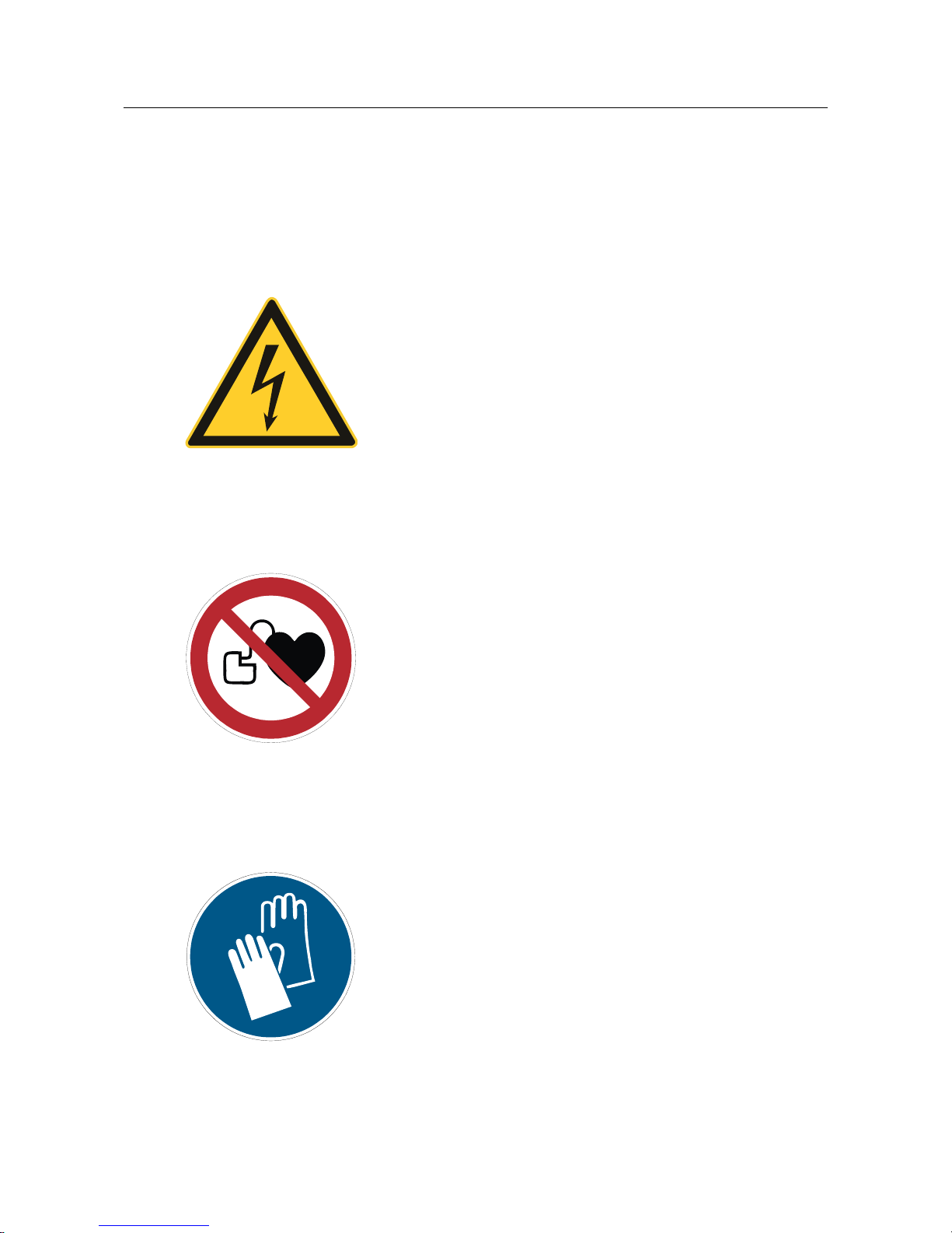
CAUTION! DANGEROUS ELECTRICAL VOLTAGE
(warning notice on the switch cabinet)
On being connected to the voltage supply (3x 400 V), the grinding
machine becomes electrically live and touching its live parts directly
could be life-threatening.
Live machine parts may be opened only by authorised, trained
personnel.
The grinding machine must be separated from the mains supply
before carrying out servicing, maintenance and repair jobs on it.
CAUTION! Pacemakers (prohibition sign on the safety doors)
A powerful magnet is installed in the machine. To avoid possible
malfunctions in the pacemaker, a minimum distance of 30 cm
between the magnetic clamping plate and the implant must be
observed.
1.3.2 General mandatory signs
The following general mandatory signs must be observed:
CAUTION! RISK OF INJURY ON THE BLADE
Work on the grinding machine involves the sharpening of blades
which could cause cut injuries due to their sharpness.
Wearing protective gloves is mandatory when carrying out such
jobs.
Be careful when transporting blades.
Protective gloves should be worn when changing the coolant (see
Safety Data Sheet on “Coolant Lubricant”).
1. Important notes
Page 8
9
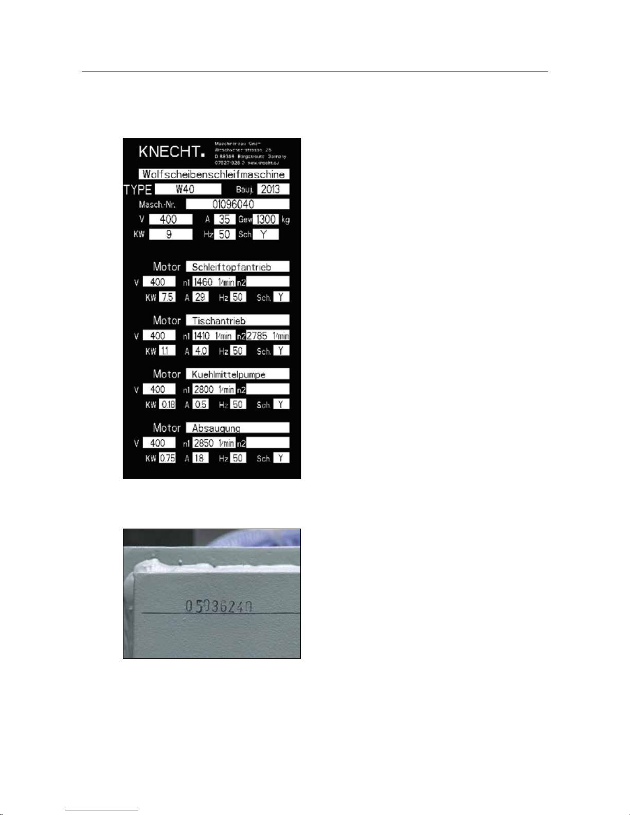
1.4 Rating plate and machine serial number
The rating plate is located on the right side of the
machine behind the control panel
.
The machine serial number is located on the rating plate and in the machine room, visible through
the opening of the extraction unit.
1. Important notes
Figure 1-2 Machine serial number
Figure 1-1 Rating Plate
Page 9

10
1.5 Figure and item numbers in the operating instructions
If the text refers to a machine component shown in a figure, then a figure or item number is
added in brackets after the machine component.
Example: (7-1/1) denotes figure number 7-1, item 1.
The workpieces are placed on the rotary table (7-1/1) for
machining. The rotary table has an electric magnet for
fixing the workpiece. The strength of the magnetic field is
divided into six levels and can be controlled.
The rotary table is powered by a spur gear. Two speeds are
available.
1. Important notes
Figure 7-1 Rotary table
1
Page 10

11
2.1 Basic safety instructions
2.1.1 Observe notes in the operating instructions
The basic prerequisite for the safe handling and uninterrupted operation of this grinding machine
is knowledge of the basic safety instructions and regulations.
• These operating instructions contain important notes on how to operate the grinding machine
safely.
• All persons carrying out work on the grinding machine must follow these operating instructions,
in particular the safety notices.
• In addition, the accident prevention rules and regulations applicable at the place of use of the
machine must also be observed.
2.1.2 Operator's duty
The operator is obliged to allow only those persons to work on the grinding machine, who
• are familiar with the basic occupational safety and accident prevention regulations and have
been trained and instructed in the handling of the grinding machine,
• have read the operating instructions, particularly the “Safety” section, and have read and understood the warning notes. They have given a signed confirmation of this in writing.
Checks are also carried out at regular intervals to determine whether the worker is fulfilling his
obligation to observe safety at work.
2.1.3 Obligations on the part of the personnel
All the personnel working on the grinding machine shall be obliged to
• observe the basic occupational safety and accident prevention regulations,
• read the operating instructions, particularly the “Safety” chapter, and the warning notes. They
must provide signed confirmation of this in writing.
2.1.4 Hazards associated with the handling of the machine
The grinding machine has been built to the latest technological standards and the acknowledged
rules of technical safety. In spite of that, its use presents inherent risks which could result in bodily
harm or even death of the user or third parties, or impairment of the grinding machine or other
property.
The grinding machine may be used only:
• for the intended purpose, and
• in faultless condition with regard to safety-relevant aspects.
2. Safety
Page 11

12
2. Safety
Faults that could impair safety must be eliminated immediately.
2.1.5 Malfunctions
If safety-relevant malfunctions occur in the grinding machine, or if the processing behaviour
indicates that such malfunctions may have occurred, the grinding machine must be stopped
immediately and until such time as the malfunction has been found and eliminated.
Allow only authorised technical staff to eliminate the malfunctions.
2.2 Use as intended
The grinding machine is only designed for surface grinding mincing plates and knives, also
referred to as workpieces in this document.
All blades must be clamped in the centre of the magnetic table.
Any other use is considered improper use. KNECHT Maschinenbau GmbH assumes no liability for
damages resulting from improper use. The user alone bears the risk in such cases.
Use as intended includes the observance of all the instructions in the operating instructions.
The grinding machine is being used improperly, if, e.g.,
• devices are not fastened properly.
• workpieces other than mincing plates or knives are ground.
2.3 Warranty and Liability
Warranty and liability claims in case of personal injuries or property damage are excluded if such
damage is attributable to one or more of the following causes:
• improper use of the grinding machine,
• improper transportation, commissioning, operation and maintenance of the grinding machine,
• operating the grinding machine with defective safety devices, or improperly attached or
malfunctioning safety and protective equipment,
• ignoring the operating instructions with regard to transportation, commissioning, operation,
maintenance and repair of the grinding machine,
• unauthorised structural alterations to the grinding machine,
• unauthorised modification, e.g. of the drive conditions (power and speed), and
• insufficient monitoring of machine parts that are exposed to wear.
Page 12

13
• use of unapproved replacement and wear parts
Use only original replacement and wear parts. If parts are purchased from external suppliers, it
cannot be guaranteed that they will be constructed and manufactured to withstand the stresses
and provide the required level of safety.
2.4 Safety regulations
2.4.1 Organisational measures
All the existent safety devices must be checked regularly.
Observe prescribed intervals for recurring maintenance work or as specified in the operating
instructions.
2.4.2 Protective devices
Before commissioning the grinding machine, it is important to ensure that all protective equipment is properly mounted and in functional condition.
Protective equipment may be removed only after the machine has stopped and has been secured
against accidental restarting of the grinding machine.
If sub-components are supplied, the protective equipment must be correctly attached by the
operator according to the instructions.
2.4.3 Informal safety measures
The operating instructions must be permanently available at the place of use of the grinding
machine. In addition to the operating instructions, the generally applicable as well as the locally
relevant accident prevention regulations must also be made available and observed.
All the safety alert symbols and danger warnings on the grinding machine must be complete and
clearly legible.
2.4.4 Selection and qualifications of the personnel
Only trained and instructed personnel may work on the grinding machine. The minimum legal
age for employment must be observed.
The responsibilities of the personnel must be clearly assigned, i.e. commissioning, operation,
maintenance and repair, etc.
Personnel still in the training or instruction phase may only be allowed to work on the grinding
machine under the permanent supervision of an experienced person.
2. Safety
Page 13

14
2.4.5 Machine control system
Do not make any changes to the software program under any circumstances. Parameters that the
operator can set himself are excluded from this prohibition.
Only trained and instructed personnel are allowed to switch on the machine.
2.4.6 Safety measures in normal operation
Refrain from any method of working which may pose a risk to safety. Only operate the grinding
machine if all the safety devices are installed and fully functional.
Check the grinding machine for external signs of damage and correct operation of the safety
devices at least once every shift.
Report any changes (including operating behaviour) immediately to the competent department / person. Where required, shut down the grinding machine immediately and secure against
restarting.
Before switching on the grinding machine, ensure that no one is exposed to any risk from the
start-up of the machine.
If there are any functional faults, immediately stop the machine and secure against restarting.
Have the faults eliminated immediately.
2.4.7 Dangers due to electrical power
Work on electrical units or operating materials may only be performed by a qualified electrician in
accordance with electrical rules.
Defects, such as a damaged cable, cable connections, etc., must be immediately rectified by an
authorised specialist.
Cables marked in yellow are electrically live even when the main switch
is in off position.
CAUTION
2.4.8 Particular danger zones
In the area of the grinding wheel, there is a hazard of pinching and being drawn in (e.g. clothing,
fingers and hair). Suitable personal protective equipment must be worn.
2. Safety
Page 14

15
2.4.9 Servicing (maintenance, repair) and fault rectification
Maintenance work is to be carried out on schedule by trained personnel. Inform operating
personnel before starting repair work. The responsible supervisor is to be named.
For all service work, the grinding machine is to be disconnected from the power supply and
secured against accidental restarting. Pull out the mains plug. Cordon off the servicing area, as
far as possible.
After completion of the maintenance work and fault rectification, install all the safety devices and
check whether they are fully functional.
2.4.10 Structural alterations to the grinding machine
Modifications, retrofitting or rebuilds of the grinding machine are not allowed without the permission of the manufacturer. This also applies to the installation and adjustment of safety devices.
No alterations may be carried out without prior written permission from KNECHT Maschinenbau
GmbH.
Immediately replace machine parts which are not in perfect condition.
Use only original replacement and wear parts. If parts are purchased from external suppliers, it
cannot be guaranteed that they will be constructed and manufactured to withstand the stresses
and provide the required level of safety.
2.4.11 Cleaning the grinding machine
Cleaning agents and materials used must be handled properly and disposed of in an environmentally friendly manner.
Ensure that wear and replacement parts are disposed of in a safe and environmentally friendly
way.
2.4.12 Oils and greases
When handling oils and greases, follow the safety instructions for the product. Observe special
instructions for the foodstuffs sector.
2.4.13 Relocation of the grinding machine
Even when moving the machine a short distance from its site, disconnect it from all external
power supply sources. Before restarting the machine, connect it properly to the current supply.
When loading or unloading, only use hoisting and load lifting equipment with sufficient loadbearing capacity. Appoint a qualified banksman (signaller) for the lifting process.
No persons other than those entrusted with this work may be present in the loading and
installation area.
2. Safety
Page 15

16
Only lift the grinding machine correctly with hoisting gear in accordance with the operating
instructions (attachment points for hoisting equipment, etc.). Only use suitable transport vehicles
with sufficient load-bearing capacity. Attach the load securely. Use suitable attachment points.
When putting in operation again, proceed only as instructed in the operating instructions.
2. Safety
Page 16

17
3. Description
3.1 Intended Use
The W 40 fully automatic surface grinding machine grinds mincing plates and knives, as well as
mincer blade sets with a diameter up to 400 mm.
3.2 Technical specifications
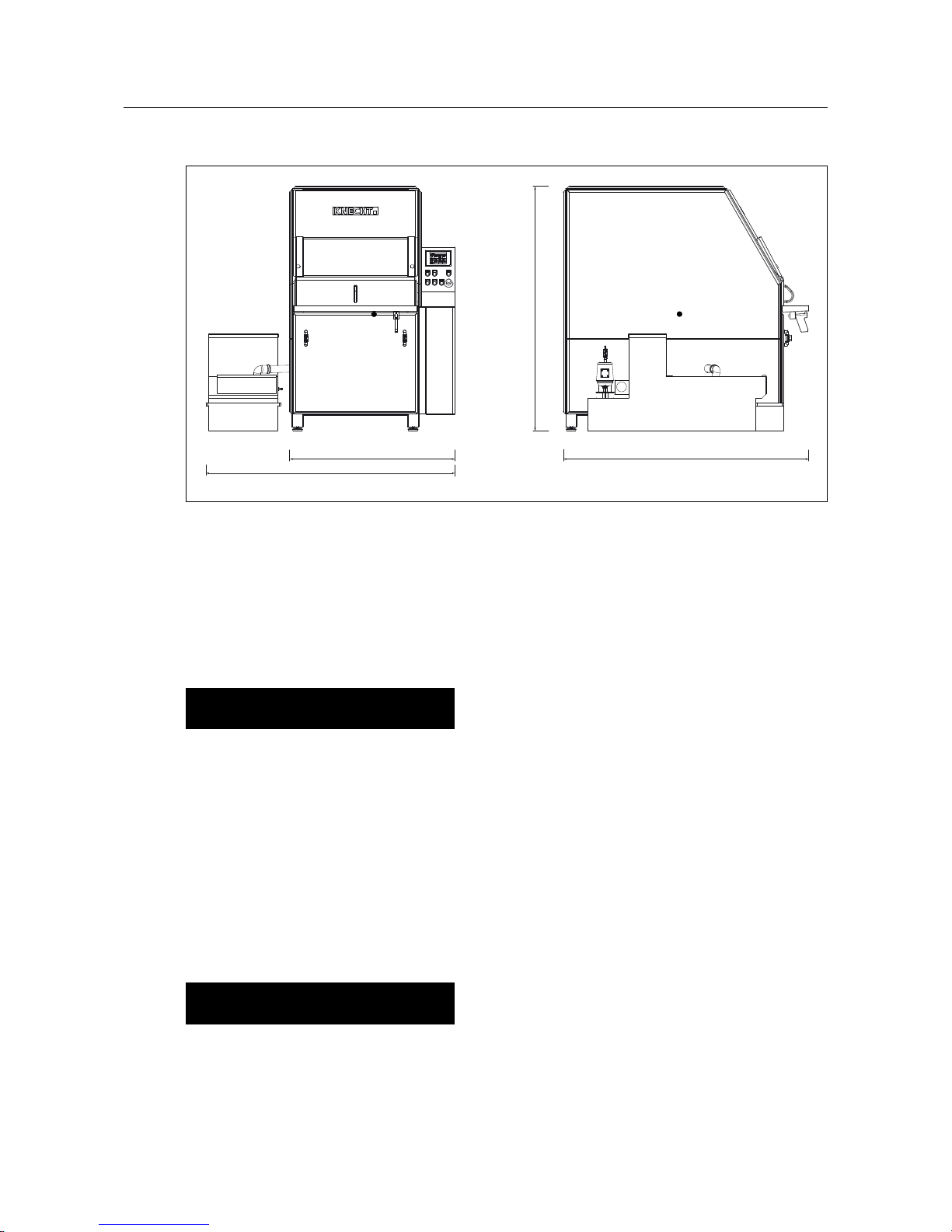
Height ������������������������������������������������������������ approx. 1800 mm
Width (incl. belt filter coolant unit) ������������������������������������ approx. 1800 mm
Depth ������������������������������������������������������������� approx. 1800 mm
Required space (WxDxH) ������������������������� approx. 3400 mm x 2600 mm x 1800 mm
Weight �������������������������������������������������������������� approx. 1200 kg
Weight of belt filter coolant unit ������������������������������������������������� 90 kg
Voltage supply* ������������������������������������������������������������ 3x 400 V
Mains frequency* �������������������������������������������������������������� 50 Hz
Connected load* �������������������������������������������������������������� 9 kW
Rated voltage* ����������������������������������������������������������������� 35 A
Back-up fuse ������������������������������������������������������������������� 25 A
Measured A-evaluated emission sound pressure level ����������������������������� 75 dB (A)
at workstation LpA**
Rotary table diameter ��������������������������������������������������������� 400 mm
Rotary table speed ����������������������������������������������������� 31 and 62 rpm
Grinding wheel diameter ������������������������������������������������������ 200 mm
Rotary table speed ���������������������������������������������������� 100 - 3000 rpm
Cutting speed with grinding wheel d.200 ��������������������������������������� 1-30 m / s
*) This data may vary depending on the electrical power supply.
**) Noise emission information according to EN ISO 3746.
A mincing plate from Turbocut (d.200 mm) was ground.
Page 17
18
Figure 3-1 Dimensions in mm
3. Description
3.3 Functional Description
With the W 40 surface grinding machine, mincing plates and knives with a diameter up to
400 mm can be ground fully automatically.
ATTENTION
The mincing plate must not protrudeover the
magnetic table.
The mincing plates are fixed on the rotary table of the W 40 surface grinding machine via magnetic tension and aligned with the help of centring pieces.
For surface grinding, mincing knives are fixed on a mincing plate with the centring piece for
blades provided.
For unusual applications, special holders are also available.
The machine is supplied with a boron nitride grinding wheel as standard. However, corundum
grinding wheels can be used as well.
ATTENTION
Only abrasives that are approved by KNECHT
Maschinenbau GmbH may be used.
An extraction unit (air purifying system) is integrated in the machine. Furthermore, there is a belt
filter coolant unit in the machine.
approx. 1200 mm approx. 1800 mm
approx. 1800 mm
approx. 1800 mm
CoG CoG
Page 18
19
3. Description
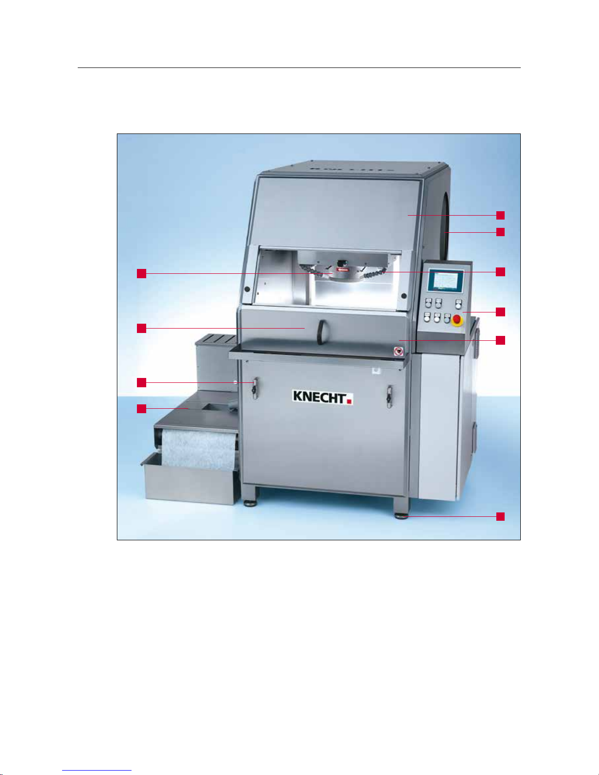
3.4 Description of the assemblies
-
1 Control panel
2 Safety doors
3 Working place light (concealed)
4 Flexible jointed coolant hose
5 Grinding unit (z-axis)
6 Rotary table (y-axis) (concealed)
7 Coolant tap
8 Belt filter coolant unit
9 Adjustable machine feet
10 Extraction unit
5
6
7
8
4
3
10
1
2
9
Figure 3-2 General view of the grinding machine
Page 19
20
3. Description
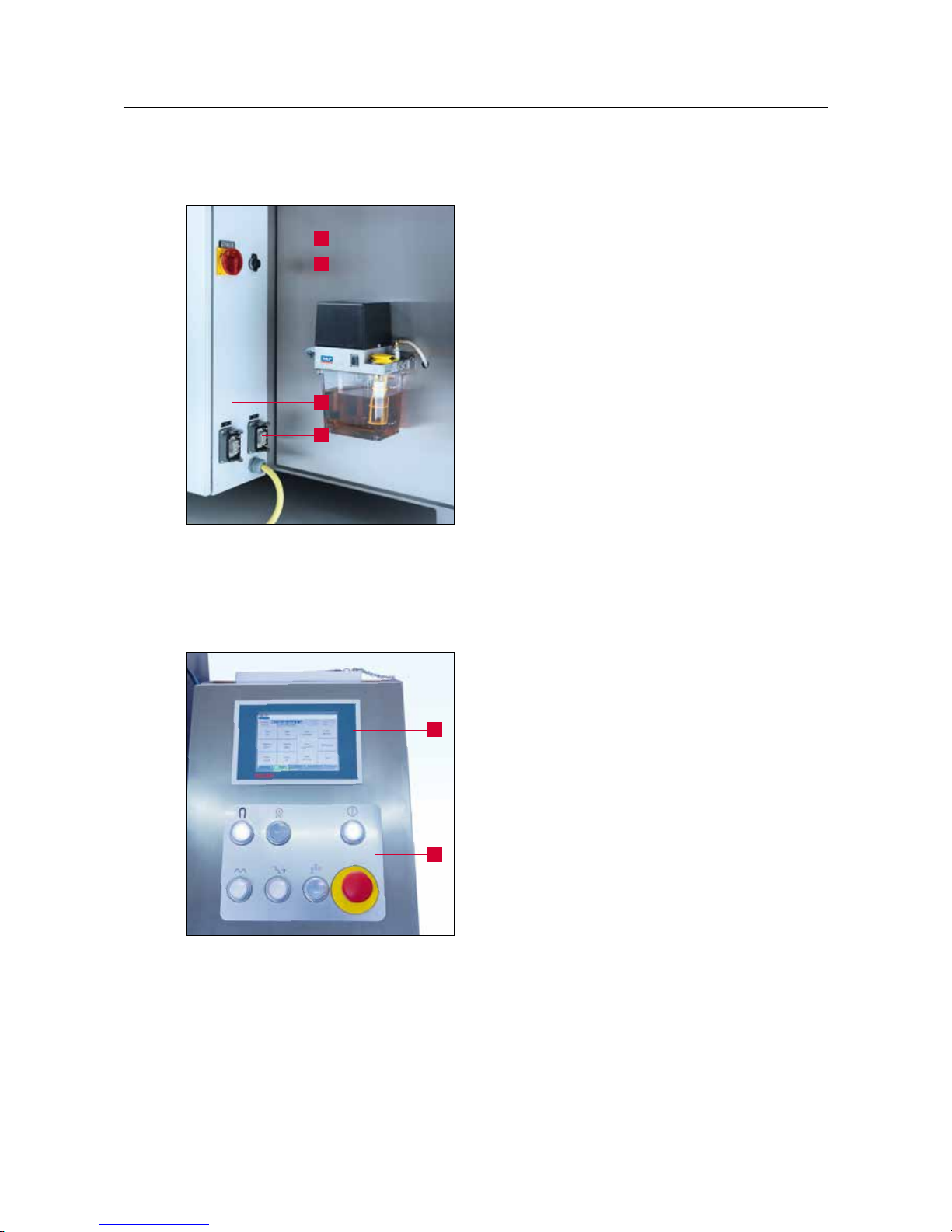
3.4.1 Switching the grinding machine on / off
The main switch (3-3/1) of the grinding machine is
located on the backside of the switch cabinet.
Turning the main switch from “0” to “I” switches
on the grinding machine.
Turning the main switch from “I” to “0” switches
off the grinding machine.
2 Connection for internet
3 Connection for coolant pump
4 Connection for belt filter coolant unit
3.4.2 Control system in general
The machine is controlled via the control panel on
the right side of the machine.
The program is automatically loaded when the
machine is switched on. The user interface is
activated only when the “Control ON” button is
pressed.
The machine is operated via the touch panel (34/1) and the buttons (3-4/2).
Figure 3-3 Main switch
2
1
3
4
Figure 3-4 Control panel
1
2
Page 20

21
1 “Magnet On / Off” button: Switches the
rotary table magnet on / off
2 “Start / Stop” button: Starts or stops the
selected product file
3 “Control On” button: Activates the controls
4 “Feed” button: Manually increases the trav-
erse speed of the axes
5 “Step” button: Feeds the grinding wheel in
defined steps
6 “Coolant On / Off” button: Switches the
coolant pump on / off
7 “Emergency Stop” button
3. Description
Figure 3-5 Control panel
1
4
5
6
7
2 3
Page 21

22
3.4.3 Layout of the user interface (main screen)
1 Status display
2 Fault messages
3 Loaded product file
4 Current processing cycle
5 Actual value of y-axis
6 Actual value of z-axis
7 Grinding time (in s)
8 Current speed of the grinding wheel
9 “Table forward”: For moving the table forward
10 “Fast motion Table”: Rapid traverse for table forward / backward
11 “Table back”: For moving the table backward
12 “Stone up”: For raising the whetstone
13 “Fast motion Stone”: Rapid traverse for whetstone up / down
14 “Stone down”: For lowering the whetstone
15 “Stone faster”: For increasing the speed of the whetstone
16 “Stone slower”: For decreasing the speed of the whetstone
3. Description
Figure 3-6 Main screen
2524232221
11
10
9
3
1
2
5 7
4
6 8
14
13
12
17
16
15
20
19
18
Page 22

23
3. Description
17 “Stone On / Off”: For switching the grinding wheel on / off
18 “Table On / Off”: For switching the table on / off
19 “Suction”: For switching the extraction unit on / off
20 “Quit”: For deleting temporary fault messages
21 “F1 Home position”: For moving the table and the grinding wheel to the base position
22 “F2 Prod. selection”: For selecting the product files
23 “F3 Product data”: For changing the product file parameters
24 “F4 Menu”: For managing the product files and language of the user interface
25 “F5 Back”: For going back to the last view
3.4.4 Belt filter coolant unit
The belt filter coolant unit (3-7) is located on the
left side of the machine.
During grinding, the work piece must be cooled
constantly. For that, fill approx. 140 litres of water
with coolant additive (see Chapter 9.1) into the
water tank.
ATTENTION
The mechanism of the grinding machine is
not rust-proof! Always use coolant additive.
Figure 3-7 Belt filter coolant unit
Page 23

24
For transporting the machine, the locally applicable safety and accident
prevention regulations must be observed.
Only transport the machine in upright position (with the machine feet
facing downwards).
CAUTION
4.1 Transport Aids
For transporting and for setting up the grinding machine, only use adequately dimensioned transport aids with a load-bearing capacity of at least 1.5 t, e.g. truck, forklift, hydraulic lift truck.
When using a forklift or a lift truck, move the fork under the grinding machine.
Bear in mind the centre of gravity of the machine. The centre of gravity (CoG) is shown in figure
3-1.
4.2 Transport Damage
If damage is detected following unloading after acceptance of the delivery, inform KNECHT
Maschinenbau GmbH and the freight forwarder about it immediately. If required, consult an
independent expert immediately.
Remove the packaging and shipping straps. Remove the shipping straps on the grinding machine.
Dispose of the packaging in an environmentally friendly way.
4.3 Transport to another installation site
For transportation to another installation site, ensure that the space requirements are fulfilled
(see Chapter 3.2).
A reliable electrical connection must be provided at the new installation site.
The grinding machine must be stable and firmly placed.
Installations on the electrical system may only be performed by an
authorised specialist or our customer service staff. Observe the locally
applicable safety and accident prevention regulations.
CAUTION
4. Transport
Page 24

25
5. Installation
5.1 Selection of qualified personnel
It is advisable to have trained KNECHT personnel perform the installation
work on the grinding machine.
We assume no liability for damage caused by improper installation.
CAUTION
5.2 Installation Site
When determining the installation site, bear in mind the space requirement for installation,
maintenance and repair work on the grinding machine.
5.3 Supply Connections
The grinding machine is delivered ready for connection with clockwise phase rotation and the
appropriate connection cable.
After connection of the power supply, the electrical phase rotation of the machine must be
checked by an electrically qualified person. The machine operates flawlessly only when the phase
rotation is clockwise.
ATTENTION
The direction of rotation of the rotary table
must be anti-clockwise (see Figure 6-4). That
of the electrical phase must be clockwise.
Confirm that the machine is correctly connected to the current supply.
CAUTION
5.4 Settings
The various components and the electrics are adjusted by KNECHT Maschinenbau GmbH before
delivery.
ATTENTION
Unauthorised changes to set values are not
permitted and may damage the grinding
machine.
Page 25

26
5.5 Initial commissioning of the grinding machine
Place the grinding machine at the installation site on a level base.
Uneven floors must be compensated for via adjustable machine feet.
Have a qualified electrician on site install the current supply.
Completely install and check the safety devices before commissioning.
Have all the protective devices checked for proper functioning by
authorised specialists before initial operation of the machine.
CAUTION
5. Installation
Page 26

27
All work on the machine may only be performed by trained personnel.
The locally applicable safety and accident prevention regulations must be
observed.
CAUTION
Set up the belt filter coolant unit and fill with
water and coolant additive as described in
Chapter 3.4.4.
For information on the coolant additive, see
Chapter 9.1.
Connect the power plug (CEE plug) to the power socket provided on site (3x 400 V, 32 A) and
switch the main switch to “I”.
Press the “Control On” button (6-2/1) on the
control panel. The control unit is now activated.
Press the “Magnet On / Off” button (6-2/2).
6. Commissioning
Figure 6-1 Filling the belt filter coolant unit
Figure 6-2 Control panel
2 1
Page 27

28
1
1
Figure 6-4 Check the direction of rotation
Press “Table On / Off” (6-3/1) and “Stone On / Off”
(6-3/2) buttons on the touch panel of the main
screen to switch both on.
The rotary table and the grinding wheel start
rotating.
Check the direction of rotation.
The direction arrows (6-4/1) show the direction of
rotation of the rotary table and grinding wheel.
Where necessary, switch the pole changer plug.
ATTENTION
In the event of an incorrect connection, the
grinding wheel and the rotary table can turn
opposite to the specified direction of rotation.
An incorrect direction of rotation can result in
the grinding wheel coming loose.
During commissioning, check the direction of
rotation of the rotary table first. The rotary
table must turn anti-clockwise.
After ensuring the prescribed direction of rotation, once again press the “Table On / Off” (6-3/1)
and “Stone On / Off” (6-3/2) buttons on the touch
panel to switch off the rotary table and the grinding wheel.
6. Commissioning
Figure 6-3 Main screen
1
2
Page 28

29
7.1 Switching on the grinding machine
Set the main switch (3-3/1) to “I”. Press the “Control On” button (3-5/3). The control unit is now
activated.
7.2 Rotary table
The workpieces are placed on the rotary table (71/1) for machining. The rotary table has an electric
magnet for fixing the workpiece. The strength of
the magnetic field is divided into six levels and can
be controlled.
The rotary table is powered by a spur gear. Two
speeds are available.
7.3 Workpiece holder
To insert a workpiece, the rotary table can be
moved to the change position. For that, move the
table and the grinding wheel to the initial position
via the “Home Position” button (3-6/21) on the
touch panel.
Small workpieces are held via centring pieces
(7-2/1). The centring pieces are used to align the
workpiece correctly on the rotary table. The relevant centring piece is inserted in the hole in the
centre of the rotary table.
Large workpieces are aligned centrally without
centring pieces. The edge of the rotary table and
the grooves on the rotary table can be used as an
orientation aid.
The workpiece is clamped with the electromagnetic table. Before each grinding process, the
magnet of the rotary table is activated by pressing
the “Magnet On” (3-5/1) button.
7. Operation
Figure 7-2 Workpiece holder
1
1
Figure 7-1 Rotary table
Page 29

30
7.4 Defining the working position
The working position of the rotary table differs
depending on the size of the workpiece. The correct working position is reached if the workpiece
is covered by the grinding wheel from the bore
to the outer edge and the grinding wheel is just
above the workpiece.
The position of the rotary table is defined via the
“Table forward” (3-6/9) and “Table back” (3-6/11)
touch panel button.
Rough adjustment can be carried out by activating “Fast motion Table” (3-6/10) and pressing the
relevant buttons. For fine adjustment, deactivate
“Fast motion Table”.
The position of the grinding unit is defined via the
“Stone Up” (3-6/12) and “Stone Down” (3-6/14)
touch panel buttons.
Rough adjustment can be carried out by activating “Fast motion Stone” (3-6/13) and pressing the
relevant buttons. For fine adjustment, deactivate
“Fast motion Stone”.
ATTENTION
Fast motion highlighted in green: Unit
traverses continuously without interruption.
Fast motion highlighted in grey: Unit
traverses a predefined distance.
When grinding mincing knives, it is important
to ensure that the grinding wheel does not
touch the collar of the knife.
7. Operation
Figure 7-3 Position of rotary table
Page 30

31
Figure 7-4 Interior
7.5 Adjusting the coolant supply
The coolant pump is switched on and off when
the control is activated by pressing the “Coolant
On / Off” (3-5/6) button. The coolant supply can
be controlled with the coolant taps (7-4/1).
Turning the coolant tap clockwise reduces the
coolant feed. Turning the coolant tap counterclockwise opens the coolant tap and releases the
coolant supply.
The jointed coolant hoses (7-4/2) are flexible and
must be set so that the coolant flows directly onto
the workpiece.
ATTENTION
Do not direct the coolant straight at the
sliding cover (7-4/3).
When grinding, ensure that the workpiece
is always adequately supplied with coolant,
otherwise overheating and associated damage could occur in the metal structure of the
workpiece. Check the coolant level regularly.
7. Operation
1
1
2
3
2
Page 31

32
7. Operation
7.6 Grinding of mincing plates
Switch on the machine (see Chapter 3.4.1) and
activate the control unit with the “Control On”
(3-5/3) button.
Place and centre the mincing plate on the rotary
table. For small workpieces, use centring pieces
(7-2/1).
Fix the mincing plate in place by pressing the
“Magnet On / Off” button (3-5/1).
Close the safety doors (3-2/2).
ATTENTION
The machine is electrically secured and the
units can only be switched on with the safety
doors closed and active magnet switched on.
Now the mincing plates are ground as described
in Chapter 8.1 “Fully automatic grinding”, Chapter 8.2 “Automatic grinding with manual touching” or Chapter 8.3 “Manual grinding”.
ATTENTION
It is important to ensure that the correct
product file is active.
The mincing plate can now be removed and
ground on the rear side. To ensure a consistent
level of quality, the first side is then ground again.
ATTENTION
The coolant must not be directed straight at
the sliding cover (7-4/3), as water will escape.
Figure 7-5 Mincing plate on rotary table
Page 32

33
Figure 7-6 Sharpening of mincing knives
3
1
2
7. Operation
7.7 Grinding of mincing knives
To grind mincing knives, switch on the machine
(see Chapter 3.4.1) and activate the control unit
with the “Control On” (3-5/3) button.
The mincing knife (7-6/1) is placed on a surfaceground mincing plate (7-6/2). The bushing is
inserted in the bore of the mincing plate. Centre
the mincing plate and mincing knife with the flat
centring piece for mincing knives (7-6/3).
Fix the mincing knife in place by pressing the
“Magnet On / Off” button (3-5/1).
NOTICE
The knife is not held with magnetic force
here. In this case, switching on the magnetic
table only serves to release the control so
that the grinding drives can be switched on.
When grinding mincing knives, it is important to
ensure that the grinding wheel does not touch the
collar of the knife. The position of the rotary table
can be adjusted exactly via the “Table forward”
(3-6/9) or “Table back” (3-6/11) touch panel buttons or via the “Process Data – Product Diameter”
(8-24/2) product file.
Now the mincing knives are ground as described
in Chapter 8.1 “Fully automatic grinding”, Chapter 8.2 “Automatic grinding with manual touching” or Chapter 8.3 “Manual grinding”.
ATTENTION
It is important to ensure that the correct
product file is active.
Page 33

34
7. Operation
The mincing knife can now be removed and
ground on the rear side.
To ensure a consistent level of quality, the first side
is then ground again.
ATTENTION
The coolant must not be directed straight at
the sliding cover (7-4/3), as water will escape.
Page 34

35
7. Operation
7.8 Dressing the corundum grinding wheel
If the grinding capacity decreases during grinding,
the grinding wheel must be dressed.
Position the dressing device (7-7/1) on the rotary
table and switch on the magnet of the rotary table
by pressing the “Magnet On / Off” (3-5/1) button.
Select and activate the “Trimming grinding
wheel” (7-8/1) product file.
Press the “Start / Stop” button (3-5/2).
Table and grinding wheel automatically move to
touching position.
The grinding wheel remains positioned above the
diamond. Now lower the grinding wheel via the
“Fast motion Stone” (7-9/1) and “Stone down”
(7-9/2) touch panel buttons until it scrapes against
the diamond.
ATTENTION
Fast motion highlighted in green: Unit
traverses continuously without interruption.
Fast motion highlighted in grey: Unit
traverses a predefined distance.
Figure 7-7 Dressing the corundum grinding
wheel
Figure 7-8 Activating the product file
Figure 7-9 Dressing the grinding wheel
1
2
1
1
Page 35

36
7. Operation
Press the “Start / Stop” button (7-10/1).
The grinding wheel is automatically trued at an
angle.
The machine then moves back to home position.
Figure 7-10 Control panel
1
Page 36

37
7.9 Changing the grinding wheel
The grinding wheel can easily be changed with
the help of the lock and the special key. To release the grinding wheel, insert the retaining pin
(7-11/1) and simultaneously rotate the grinding
wheel until the shaft blocks further rotation. Then
loosen the flange with the special key (7-11/2).
The new grinding wheel can only be mounted
when the shaft is blocked. Hand-tighten the
flange.
After changing the grinding wheel, re-adjust the
grinding wheel protective equipment. The grinding wheel must not protrude under the guard by
more than 1.5 cm.
ATTENTION
Remove the retaining pin.
NOTICE
For optimal working, only use abrasives
recommended by KNECHT.
Make sure that the retaining pin is released
and removed when the machine is switched
on (turn the wheel briefly by hand).
For all work on the grinding machine, the locally applicable safety and
accident prevention regulations as well as instructions in the “Safety”
and “Important Notes” section of the operating instructions must be
observed.
Use only original replacement and wear parts. If parts are purchased from
external suppliers, it cannot be guaranteed that they will be constructed
and manufactured to withstand the stresses and provide the required
level of safety.
After a new grinding wheel is mounted, a test run must be carried out.
To do this, lower the grinding wheel to 5 mm above the rotary table and
run with water for 10 minutes.
CAUTION
7. Operation
Figure 7-11 Changing the grinding disk
1
2
Page 37

38
8.1 Fully automatic grinding
Press the “Control On” (8-1/1) button.
Activate the relevant product file
as necessary (see Chapter 8.4).
Place the workpiece. Close the safety doors.
Press the “Magnet On / Off” (8-1/2) and
“Start / Stop” (8-1/3) buttons.
All the units are started; table and grinding wheel
move to working position in front of the workpiece.
The grinding wheel slowly approaches the workpiece until it touches the surface. The machine
runs through the grinding cycles in accordance
with the product file.
Subsequently, the units move back to base position and shut down fully automatically.
The workpiece can be removed.
8. Control system
Figure 8-1 Control panel
2 3 1
Page 38

39
8.2 Automatic grinding with manual touching
Press the “Control On” (8-2/1) button.
Activate the relevant product file as necessary (see
Chapter 8.4).
Place the workpiece. Close the safety doors.
Press the “Magnet On / Off” (8-2/2) and
“Start / Stop” (8-2/3) buttons.
All the units are started; table and grinding wheel
move to working position in front of the workpiece.
The surface of the workpiece is approached with
the help of the “Fast motion Stone” (8-3/1) and
“Stone down” (8-3/2) touch panel buttons.
Press the “Start / Stop” button (8-2/3). The machine runs through the grinding cycles in accordance with the product file. The grinding wheel
sparks out twice.
The units move back to base position and shut
down fully automatically.
The workpiece can be removed.
ATTENTION
Fast motion highlighted in green: Unit
traverses continuously without interruption.
Fast motion highlighted in grey: Unit
traverses a predefined distance.
8. Control system
Figure 8-2 Control panel
Figure 8-3 Main screen
1
2
2 3 1
Page 39

40
8. Control system
NOTICE
To be able to grind automatically with manual touching, the “Option Touching Active”
parameter (8-4/1) in the product file must be
set to “false”.
See also Chapter 8.6.2.
Figure 8-4 Touching Active option
1
Page 40

41
8.3 Manual grinding
Press the “Control On” (8-5/1) button.
Place the workpiece. Close the safety doors.
Press the “Magnet On / Off” (8-5/2) and “Coolant
On / Off” (8-5/3) buttons.
First activate “Suction” (8-6/1) on the touch panel,
then press “Table On / Off” (8-6/2) and “Stone
On / Off” (8-6/3).
All the required units are switched on now. The
relevant buttons are illuminated and the touch
panel buttons (8-7) are highlighted in green.
8. Control system
Figure 8-5 Control panel
Figure 8-6 Main screen
3
1
2
Figure 8-7 Switched-on units
2
3
1
Page 41

42
Now “Table forward” (8-8/1) and “Stone down”
(8-8/2) are pressed to move the table (y-axis) and
the grinding wheel (z-axis) to working position
and to grind the workpiece.
ATTENTION
Fast motion highlighted in green: Unit
traverses continuously without interruption.
Fast motion highlighted in grey: Unit
traverses a predefined distance.
After grinding, raise the grinding wheel by pressing “Stone up” (8-9/1). Move the machine back to
base position with the “F1 Home Position” (8-9/2)
command.
Switch off all the units manually.
The workpiece can be removed.
8. Control system
Figure 8-8 Moving the table and the grinding
wheel to the working position
1
2
Figure 8-9 Home position
2
1
Page 42

43
8.4 Activating the product file
You can grind various mincing plates and knives with the most diverse parameters. A separate
product file for each grinding task is stored. This product file must be selected and loaded in the
automatic operating modes (Chapter 8.1 and 8.2) prior to grinding.
The procedure is as follows:
Activate the “F2 Prod. selection” (8-10/1) touch
panel button. A new window (8-11) opens.
Select the required product file so that it is highlighted in blue as shown in the figure (8-11/1).
Load the product file in the control unit via the
“F4 Activate” (8-11/2) touch panel button.
The program automatically switches back to the
main screen.
The new product file appears in the “Product”
row (8-12/1). The new parameters are now loaded
by the control unit.
8. Control system
Figure 8-12 Main screen
Figure 8-10 Main screen
1
Figure 8-11 Selecting the product file
1
1
2
Page 43

44
8.5 Renaming, creating and deleting the product file
ATTENTION
No parameters are changed.
Product files can be renamed, deleted and new
ones created by copying.
The procedure is as follows:
Activate the “F2 Prod. selection” (8-13/1) touch
panel button.
A new window (8-14) opens.
Select the required product file so that it is highlighted in blue as shown in the figure (8-14/1).
Select the relevant touch panel button: “F1
Rename” (8-14/2), “F2 Delete” (8-14/3) or “F3
Copy” (8-14/4).
8. Control system
Figure 8-13 Main screen
Figure 8-14 Editing the product file
4 5 632
1
1
Page 44

45
8.5.1 Renaming the product file
On pressing “F1 Rename” (8-14/2), a window as
displayed in the figure on the left (8-15) opens.
Edit the file name (8-15/1) using the keyboard and
confirm with “OK” (8-15/2).
The window closes. The renamed file appears in
the product file directory.
Then activate a product file with “F4 Activate” (814/5) or return to the main screen with “F5 Back”
(8-14/6).
8.5.2 Creating the product file
On pressing “F3 Copy” (8-14/4), a window as
displayed in the figure on the left (8-16) opens.
Edit the file name (8-16/1) using the keyboard and
confirm with “OK” (8-16/2).
The window closes. The new file appears in the
product file directory.
Continue with Chapter 8.6 to edit the parameters
of the product file.
8.5.3 Deleting the product file
On pressing “F2 Delete” (8-14/3), a pop-up
window (8-17/1) opens.
Confirm with “Yes” (8-17/2); cancel with “No”.
The pop-up window closes.
Then activate a product file with “F4 Activate”
(8-17/3) or return to the main screen with “F5
Back” (8-17/4).
8. Control system
Figure 8-16 Creating the product file
Figure 8-17 Deleting the product file
Figure 8-15 Renaming the product file
2
1
1
1
2
43
2
Page 45

46
8.6 Editing the parameters of the product file
The parameters of the product files can be
changed as follows:
Press the “F3 Product data” (8-18/1) touch panel
button on the main screen.
A new window (8-19) opens.
There are four different parameter groups:
“RECIPE DATA” (8-19/1): general data (see
Chapter 8.6.1)
“Process data” (8-19/2): Grinding process data
(see Chapter 8.6.2)
“Polishing [1]” (8-19/3): Sparking out process data
1 (see Chapter 8.6.3)
“Polishing [2]” (8-19/4): Sparking out process data
2 (see Chapter 8.6.3)
The active group is always indicated with a green
arrow. To activate a group, press the name. The
arrow moves forward and the group is highlighted
in blue.
8. Control system
Figure 8-18 Main screen
1
Figure 8-19 Parameter groups
2
1
3
4
Page 46

47
8.6.1 Meaning of the parameter “RECIPE DATA”
“Magnet strength (0 = off, 6 = max)” (8-20/1):
Magnet strength from 0 = off to 6 = max
“Trimming active (8-20/2)”: Dress the grinding
wheel (False = not active, True = active)
Changing the parameters: Tap on the relevant
((8-20/1) or (8-20/2)) button highlighted in yellow.
Tap on “Numbers” to open the window as shown
in (8-21); tap on “Values” to open the window as
shown in (8-22).
Select the desired number and confirm with “OK”
(8-21/1).
The “Cancel” touch panel button closes the window without accepting the number.
In the window for “Values”, select between
“true” and “false” and confirm with “OK”
(8-22/1).
The “Cancel” touch panel button closes the
window without accepting the value.
ATTENTION
Save the changed values with the “F2 Save”
(8-20/3) touch panel button. If a current
product file is changed, overwrite via the “F1
Activate” (8-20/4) touch panel button of the
control system.
8. Control system
Figure 8-21 Editing the “Numbers” parameter
Figure 8-22 Editing the “Values” parameter
Figure 8-20 “RECIPE DATA” parameter
1
1
1
2
34
Page 47

48
8.6.2 Meaning of the parameter “Process data”
1 “Product height”: height of the workpiece (in mm)
2 “Product diameter”: diameter of the workpiece (in mm)
3 “Table fast speed”: speed of the rotary table (True = fast, False = slow)
4 “Grinding disk speed”: speed of the grinding wheel (rpm)
5 “Grinding cycles”: number of grinding cycles
6 “Deliver way”: path that is fed from cycle to cycle (in mm)
7 “Grinding duration”: dwell time between cycles (in s)
8 “Option Touching active”: touching (True = automatic, False = manual)
9 “Option Magnet back to BasePos”: approaching the base position (True = yes, False = no)
To change the parameters, tap on the relevant button highlighted in yellow.
Tap on “Numbers” to open the window as shown in (8-24); tap on “Values” to open the window
as shown in (8-25).
8. Control system
Figure 8-23 “Process data” parameter
1
2
3
4
5
6
7
8
9
10 11
Page 48

49
Select the desired number and confirm with “OK”
(8-24/1).
The “Cancel” touch panel button closes the window without accepting the number.
In the window for “Values”, select between
“true” and “false” and confirm with “OK” (825/1).
The “Cancel” touch panel button closes the window without accepting the value.
ATTENTION
Save the changed values with the “F2 Save”
(8-23/11) touch panel button. If a current
product file is changed, overwrite via the “F1
Activate” (8-23/10) touch panel button of the
control system.
8. Control system
Figure 8-24 Editing the “Numbers” parameter
Figure 8-25 Editing the “Values” parameter
1
1
Page 49

50
8. Control system
8.6.3 Meaning of the parameter “Polishing [1]” and “Polishing [2]”
“Active” (8-26/1): Spark out cycle active (True =
yes, False = no)
“Position offset” (8-26/2): Path that is covered by
the cycle (in mm)
“Duration” (8-26/3): Dwell time between cycles
(in s)
To change the parameters, tap on the relevant
button highlighted in yellow.
Tap on “Numbers” to open the window as shown
in (8-27); tap on “Values” to open the window as
shown in (8-28).
Select the desired number and confirm with “OK”
(8-27/1).
The “Cancel” touch panel button closes the
window without accepting the number.
In the window for “Values”, select between
“true” and “false” and confirm with “OK”
(8-28/1).
The “Cancel” touch panel button closes the
window without accepting the value.
ATTENTION
Save the changed values with the “F2 Save”
(8-26/5) touch panel button. If a current
product file is changed, overwrite via the “F1
Activate” (8-26/4) touch panel button of the
control system.
Figure 8-26 “Polishing [1]” parameter
4 5
1
2
3
Figure 8-27 Editing the “Numbers” parameter
Figure 8-28 Editing the “Values” parameter
1
1
Page 50

51
8.7 Language
The user interface language can be changed to
the language of the country of use. The parameter
descriptions are always in English.
Press the touch panel button “F5 Back” (8-29/1)
to go back to the start screen.
Press the “F4 Language” (8-30/1) touch panel
button.
A new window (8-31) opens.
The desired language is selected and automatically
activated by pressing the corresponding touch
panel button (8-31/1).
Then return to the start screen by pressing the “F5
Back” (8-31/2) touch panel button.
The main screen appears when the “F3 Production” (8-30/2) button is pressed.
8. Control system
Figure 8-31 Selecting the language
Figure 8-29 Main screen
1
Figure 8-30 Start screen
12
2
1
Page 51

52
9. Care and maintenance
9.1 Coolant additive
An anti-rust coolant additive must be added to the cooling water (see Chapter 9.1.1).
ATTENTION
No other coolant additive may be used
without the approval of KNECHT Maschinenbau GmbH.
9.1.1 Cooling lubricant maintenance plan
• Check fill level daily.
• After topping up with water, always measure concentration and if necessary top up with
cooling lubricant.
• Check cooling lubricant concentration weekly.
Cooling lubricant:
Colometa SBF-P
Refractometer °Brix: 3 - 5
Date: °BRIX Conc % Remarks
etc.
Signature
(The value read off in Brix multiplied by 1.8 is the concentration in %).
The concentration must always lie between 3 - 5 °Brix (corresponds to between 5 and 9%
concentration).
Check the cooling lubricant regularly for odour and appearance. The cooling lubricant must
be replaced at the latest every three months (biological hazard due to germ formation in the
cooling lubricant).
Maintenance plan has been enclosed for copying.
Page 52

53
Figure 9-1 Central lubrication system
9. Care and maintenance
9.2 Lubrication
All bearing points are equipped with water-tight,
lubricated anti-friction bearings and are therefore
maintenance-free.
All the lubrication points are supplied via the central lubrication system. A pulse from the control
system ensures that the lubrication points are
regularly supplied with oil.
Unscheduled pulses can be released via the touch
panel if the operator considers it necessary to
lubricate the machine (e.g. after a thorough cleaning, repair or after servicing).
See also the explanations in the lubrication schedule, Chapter 9.2.2.
ATTENTION
Always ensure that the storage tank of the
central lubrication system is sufficiently filled
with the prescribed amount of oil.
The lubrication system generally runs automatically at the programmed intervals.
9.2.1 Additional lubrication interval
If it appears that the linear rails need an additional
lubrication by the central lubrication system, then
proceed as follows:
Press the “F4 Menu” (9-2/1) touch panel button
on the main screen. A new window (9-3) opens.
Figure 9-2 Main screen
1
Page 53

54
9. Care and maintenance
Press the “F3 Manual function” (9-3/1) touch
panel button to call the manual function of the
machine.
Activate the “On” (9-4/1) touch panel button to
switch on the central lubrication unit.
Activate the “Off” (9-4/2) touch panel button to
switch it off. Otherwise, the central lubrication
unit switches off automatically after a certain
period of time.
9.2.2 Lubrication schedule and lubricant table
Lubricating work Interval OEST SHELL EXXON Mobil
Grease machine parts after
cleaning
After each
grinding
operation
– Shell Risella
917
Marcol 82
Central lubrication system Monitor fill level
as necessary
Lubricating
oil CGLP 68
– –
Figure 9-4 Manual functions
12
Figure 9-3 Menu
1
Page 54

55
9. Care and maintenance
9.3 Main tenance plan
Interval Component assembly Maintenance activity
Daily Grinding compartment Clean the interior of the sheet plates with a
washing gun
Belt filter Monitor the fill level, fill if necessary (observe
the concentration)
Central lubrication
system
Monitor the fill level; fill if necessary
Machine Visual check for damages
Weekly Extraction unit Clean the hose socket
Check filter
Monthly Magnet Lightly surface grind any unevenness
Annually Request service call from
KNECHT Maschinenbau GmbH
Page 55

56
9. Care and maintenance
9.4 Cleaning
Clean the machine after each grinding process to
prevent grinding sludge from drying, hence making it harder to remove.
After cleaning, we recommend greasing the
machine lightly with acid-free oil.
See also the explanations in the lubrication
schedule, Chapter 9.2.2.
ATTENTION
Take care not to direct the jet straight at the
sliding cover when cleaning.
The coolant pump needed for cleaning the machine is switched on and off manually as follows:
Press the “F4 Menu” (9-6/1) touch panel button
on the main screen. A new window (9-7) opens.
Press the “F3 Manual function” (9-7/1) touch
panel button to call the manual function of the
machine.
Figure 9-6 Main screen
Figure 9-7 Menu
1
1
Figure 9-5 Cleaning
Page 56

57
Press the “On” (9-8/1) touch panel button to
switch on the central lubrication unit.
Press the “Off” (9-8/2) touch panel button to
switch it off.
9. Care and maintenance
Figure 9-8 Manual functions
12
Page 57

58
10. Disassembly and disposal
10.1 Disassembly
All operating materials must be disposed of correctly.
Secure moving parts against slipping.
The disassembly must be carried out by a qualified specialist company.
10.2 Disposal
At the end of the machine service life, it must be disposed of by a qualified specialist company.
In exceptional cases and in agreement with KNECHT Maschinenbau GmbH, the machine can be
returned.
Operating materials (e.g. grinding wheels, coolants etc.) must also be disposed of correctly.
Page 58

59
11.1 Postal Address
KNECHT Maschinenbau GmbH
Witschwender Straße 26
88368 Bergatreute
Germany
Phone +49 -7527-928-0
Fax +49 -7527-928-32
mail@knecht.eu
www.knecht.eu
11.2 Service
Service management:
See postal address
service@knecht.eu
11.3 Spare parts
If you need spare parts, please use the spare parts list provided with the machine. Please place
your order as shown below.
Please always include the following information: (Example)
Machine type (W40)
Machine serial number (03114940)
Designation of assembly (table incl. drive)
Designation of individual part (Lenze transmission ...)
Item no. (16)
Drawing no. (410GA20-0090)
Quantity (1 pc.)
Please feel free to contact us with any questions.
11. Service, spare parts and accessories
Page 59

60
11. Service, spare parts and accessories
11.4 Accessories
11.4.1 Grinding wheels used
Type Dimension Suffix
Standard
Order number Remarks
Corundum d.200x78x80 K36 412B-32-0236
Corundum d.200x78x80 K36, H16 412B-32-0656
Corundum d.200x78x80 K36, I16 412B-32-0756
Boron nitride d.200x50x78 412F-80-0435
ATTENTION
No other grinding wheels may be used
without the approval of KNECHT Maschinenbau GmbH.
KNECHT Maschinenbau GmbH accepts no
liability if other grinding wheels are used.
If you require grinding wheels or other accessories, please contact our sales staff, dealers, or
KNECHT Maschinenbau GmbH directly.
Thank you for buying our product!
Page 60

61
12. Appendix
12.1 EC Declaration of Conformity
in accordance with the EC Directive 2006/42/EC
• Machinery Directive 2006/42/EC
• Electromagnetic Compatibility Directive 2004/108/EC
We hereby declare that the machine mentioned below fulfils the basic health and safety
requirements of the relevant EC Directive by virtue of the machine's construction and design
and the version placed by us on the market.
This declaration becomes void if the machine is modified in any way without our consent.
Designation of the machine: Fully automatic surface grinding machine
Type designation: W 40
Applicable harmonised standards, DIN EN ISO 12100
in particular: DIN EN ISO 13850
DIN EN ISO 13857
DIN EN 13218
DIN EN 61000-3-2 (VDE 0838-2): 2010-03
DIN EN 61000-3-3 (VDE 0838-3): 2009-06
DIN EN 55014-1 (VDE 0875-14-1): 2012-05
DIN EN 349
Responsible for the documentation: Peter Heine (Dipl. Ing. Mechanical Engineering BA)
Phone +49 -7527-928-15
Manufacturer: KNECHT Maschinenbau GmbH
Witschwender Straße 26
88368 Bergatreute
Germany
Complete technical documentation is available. The operating instructions document for the
machine is available in its original version and in the native language of the user.
Bergatreute, June 20, 2018 Managing Director
–––––––––––––––––––––––––– –––––––––––––––––––––––––– ––––––––––––––––––––––
Place, date Signature Signatory details
Page 61

KNECHT Maschinenbau GmbH
Witschwender Straße 26
■ 88368 Bergatreute ■ Germany ■ T + 49
-
7527- 928-0 ■ F + 49 -7527- 928-32
mail@knecht.eu
■ www.knecht.eu
 Loading...