

Page 1
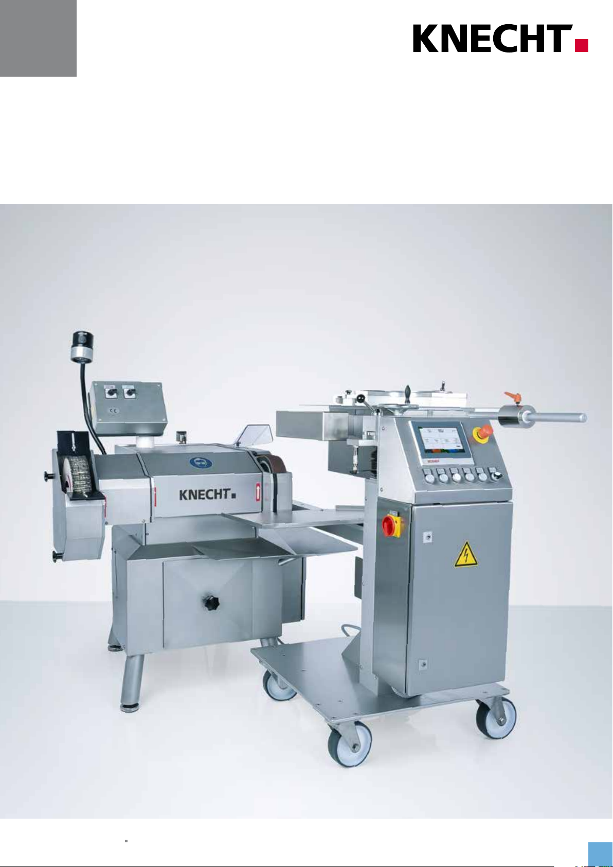
Operating Instructions
USK 230 B - HV 208 II
Automatic Grinding Machine
Status 10.2019 Version 1.0 | Translation
Page 2

Operating Instructions
USK 230 B - HV 208 II automatic grinding machine
Manufacturer
KNECHT Maschinenbau GmbH
Witschwender Straße 26
88368 Bergatreute
Germany
Telephone +49 -7527-928-0
Fax +49 -7527-928-32
mail@knecht.eu
www.knecht.eu
Documents for machine operator
Operating Instructions
Date of issue of the operating instructions
October 29, 2019
Copyright
The copyright for these operating instructions as well as other documents for the machine operator is held
by KNECHT Maschinenbau GmbH. They are provided only to customers and operators of our products and
are included with the machine.
These documents may neither be reproduced, nor made accessible to third parties, in particular rival firms,
without our express permission.
3
Page 3

Table of Contents
1. Important notes 7
1.1 Preface to the operating instructions 7
1.2 Warnings and symbols in the operating instructions 7
1.3 Warning signs and their meaning 8
1.3.1 Warning and prohibitory signs on the grinding machine 8
1.3.2 General mandatory signs 8
1.4 Rating plate and serial number 9
1.5 Figure and position numbers in the operating instructions 9
2. Safety 10
2.1 Basic safety instructions 10
2.1.1 Observe notes in the operating instructions 10
2.1.2 Obligation on the part of the operator 10
2.1.3 Obligation on the part of the personnel 10
2.1.4 Hazards involved in handling the grinding machine 10
2.1.5 Malfunctions 11
2.2 Intended use 11
2.3 Warranty and liability 11
2.4 Safety regulations 12
2.4.1 Organizational measures 12
2.4.2 Protective equipment 12
2.4.3 Informal safety measures 12
2.4.4 Selection and qualification of personnel 12
2.4.5 Machine control system 13
2.4.6 Safety measures in normal operation 13
2.4.7 Hazards due to electrical power sources 13
2.4.8 Particular hazard zones 13
2.4.9 Servicing (maintenance, repair) and fault elimination 13
2.4.10 Structural modifications to the grinding machine 14
2.4.11 Cleaning the machine 14
2.4.12 Oils and greases 14
2.4.13 Relocation of the grinding machine 14
3. Description 15
3.1 Intended use 15
3.2 Technical specifications 15
3.3 Functional description 16
3.4 Description of components 17
3.4.1 USK 230 B control panel 18
3.4.2 Coolant unit 18
3.4.3 HV 208 copy grinding device 19
3.4.4 Switching the copy grinding device on / off 19
3.4.5 HV 208 control panel 20
3.4.6 Layout of user interface (main screen) 21
3.4.7 SP 110 copy grinding plate 22
4
Page 4

Table of Contents
4. Transport 23
4.1 Means of transport 23
4.2 Transport damage 23
4.3 Transport to another installation site 23
5. Installation 24
5.1 Selection of qualified personnel 24
5.2 Installation site 24
5.3 Supply connections 24
5.4 Settings 24
5.5 Initial start-up of the grinding machine 25
6. Commissioning 26
7. Operation 29
7.1 General grinding fundamentals 29
7.2 Switching on the copy grinding device 30
7.3 Grinding the cutter knife 30
7.3. 1 Mounting the copy grinding plate 30
7.3.2 Setting the balance weight 32
7.3.3 Setting the grinding angle 33
7.3.4 Switching on the USK 230 grinding machine 33
7.3.5 Starting the grinding process 33
7.3.6 Canceling the grinding process 35
7.4 Replacing the copy grinding plate 36
7.5 Deburr cutter knife with the finned brush 38
7.6 Grinding hand knives on the wet-grinding belt 39
7.7 Changing the wet-grinding belt 40
7.7.1 Belt adjustment 41
7.8 Replacing the finned brush 42
8. Control 43
8.1 Main screen 43
8.2 Selecting product files 44
8.3 Renaming, creating, and deleting product files 45
8.3.1 Renaming product file 45
8.3.2 Renaming product file 46
8.3.3 Deleting product file 46
5
Page 5

Table of Contents
8.4 Editing product file parameters 47
8.4.1 Meaning of the “Grind” parameter 48
8.4.2 Meaning of the “Feed Cycles” parameter 50
8.5 Machine data 52
8.5.1 Grinding 52
8.5.2 Coolant controls 53
8.5.3 Settings 53
8.6 Language 54
8.7 Setting up an internet connection 55
9. Care and maintenance 56
9.1 Cleaning 56
9.2 Lubrication and maintenance 56
9.2.1 Lubrication schedule and lubricant table 57
10. Malfunctions 58
10.1 Malfunctions 58
11. Disassembly and disposal 59
11.1 Disassembly 59
11.2 Disposal 59
12. Service, spare parts and accessories 60
12.1 Postal address 60
12.2 Service 60
12.3 Spare parts 60
12.4 Accessories 61
12.4.1 Abrasives used, etc. 61
13. Annex 62
13.1 EC Declaration of Conformity 62
6
Page 6

1. Important notes
1.1 Preface to the operating instructions
These operating instructions are intended to make it easier to get to know the automatic grinding
machine, referred to in this document as grinding machine, and to use it properly for the intended purpose.
The operating instructions contain important information on how to operate the grinding machine safely, properly and cost-effectively. Observance of these instructions helps to avoid hazards,
avoid repair expenses and downtimes, and to increase the reliability as well as service life of the
grinding machine.
The operating instructions must always be accessible at the place of use of the grinding machine.
The operating instructions must be read and used by all persons entrusted with working on the
grinding machine, e.g. those entrusted with:
• Transport, installation, commissioning
• Operation, including troubleshooting in the process flow, as well as
• Upkeep (maintenance, repair).
In addition to the operating instructions and the binding accident prevention regulations applicable in the country and place of use of the machine, the generally acknowledged rules of technology with regard to safe and professional work practices are to be observed.
1.2 Warnings and symbols in the operating instructions
Heeding the following safety alert symbols / designations used in the operating instructions is
absolutely necessary:
The hazard triangle with the signal word “CAUTION” is a work safety
indicator for all work for which there is a risk of serious or fatal injury.
Special care and caution must be exercised when carrying out such work.
CAUTION
”ATTENTION” is used to draw attention to particular points in order to
ATTENTION
NOTICE
avoid damage to and / or destruction of the grinding machine and its
environment.
”NOTICE” refers to user tips and especially useful information.
7
Page 7
1. Important notes
1.3 Warning signs and their meaning
1.3.1 Warning and prohibitory signs on the grinding machine
The following warning and prohibitory signs are located on / in the grinding machine:
CAUTION! DANGEROUS ELECTRICAL VOLTAGE
(warning notice on the rear panel)
On being connected to the current supply (3x 400 V), the grinding
machine becomes electrically live and touching its live parts directly
could be life-threatening.
Current-carrying device parts may only be opened by authorized
personnel.
The grinding machine must be separated from the mains supply
before carrying out servicing, maintenance and repair work on it.
CAUTION! RISK OF INJURY FROM ABRASIVE PARTICLES
(mandatory sign on the front plate)
Grinding, polishing and deburring gives rise to grinding particles
which could enter the eyes.
Wearing protective goggles is mandatory when carrying out such
work.
1.3.2 General mandatory signs
The following general mandatory signs must be followed:
CAUTION! RISK OF INJURY FROM KNIFE
Working with the grinding machine involves grinding knives that
could cause serious cut injuries due to their sharpness.
Protective gloves must be worn when clamping and releasing
knives.
Caution when transporting blades. Use the protective equipment
provided by the knife manufacturer. Wear safety shoes and safety
apron.
8
Page 8
1. Important notes
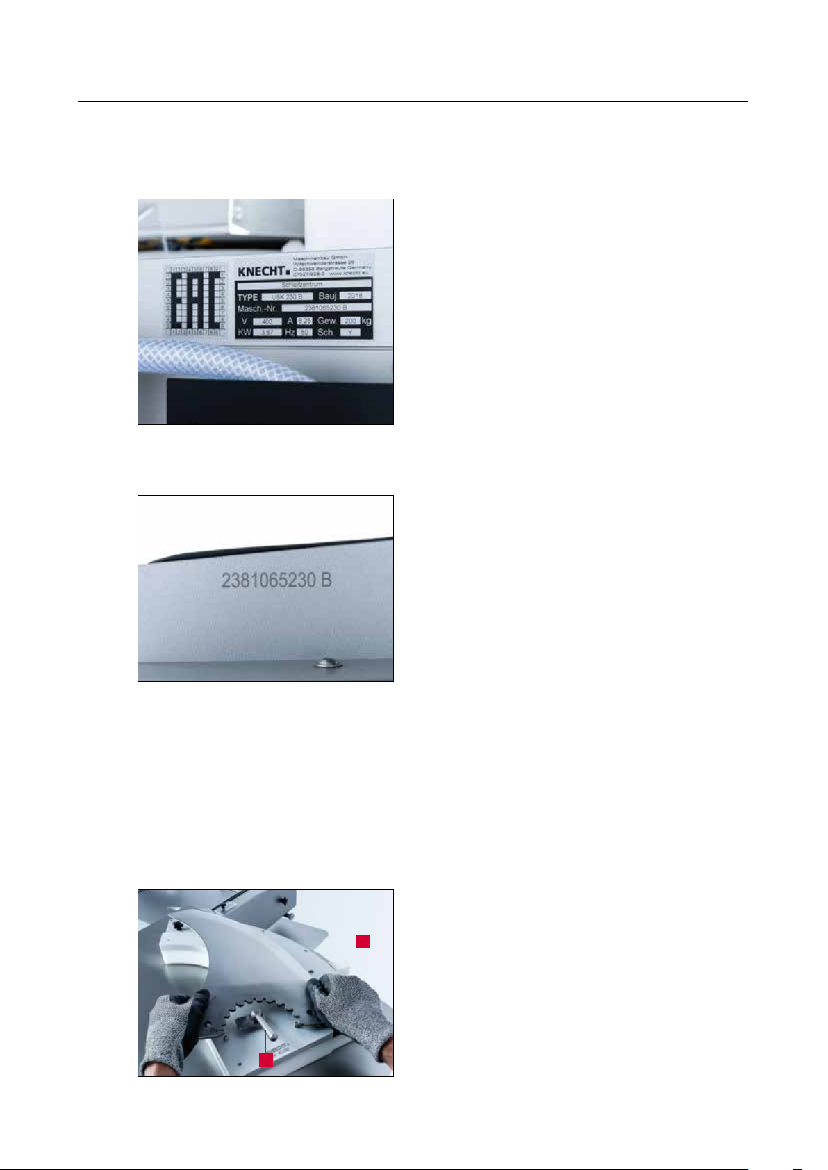
1.4 Rating plate and serial number
The rating plate is located on the rear panel of the
grinding machine.
Figure 1-1 Rating plate
The machine serial number is located on the rating
plate and on the back and right on the base plate
of the belt protection hood.
Figure 1-2 Machine serial number
1.5 Figure and position numbers in the operating instructions
If there is a reference to a machine component in the text which is depicted in an image, the
figure and item number will be given in parentheses.
Example: (7-4/1) means Figure number 7-4, item 1.
Place knife (7-4/1) on the mounting for the copy grinding
plate and turn latch (7-4/2) onto knife.
2
Figure 7-4 Clamping the knife
1
9
Page 9

2. Safety
2.1 Basic safety instructions
2.1.1 Observe notes in the operating instructions
The basic prerequisite for the safe handling and uninterrupted operation of this grinding machine
is knowledge of the basic safety instructions and regulations.
• These operating instructions contain important notes on how to operate the grinding machine
safely.
• All persons carrying out work on the grinding machine must follow these operating instructions,
in particular the safety notices.
• In addition, the rules and regulations regarding accident prevention at the place of use are to be
observed.
2.1.2 Obligation on the part of the operator
The operator is obliged to allow only those persons to work on the grinding machine, who
• are familiar with the occupational safety and accident prevention regulations and have received
instruction in handling the grinding machine,
• have read and understood the operating instructions, in particular the section entitled “Safety”
and the warning notes, and have provided signed confirmation of this.
The safety-related work of personnel will be monitored at regular intervals.
2.1.3 Obligation on the part of the personnel
All personnel working on the grinding machine shall be obliged, before starting work, to
• observe basic occupational safety and accident prevention regulations,
• read the operating instructions, particularly the section entitled “Safety” and the warning notes,
and provide signed confirmation of this.
2.1.4 Hazards involved in handling the grinding machine
10
The grinding machine has been built to the latest technological standards and the acknowledged
rules of technical safety. In spite of this, its use poses inherent risks which could result in bodily
harm or even death of the user or third persons, or impairment of the grinding machine or other
property.
The grinding machine may be used only:
• for its intended purpose
• in faultless condition with regard to safety-related aspects.
Malfunctions that may impair safety are to be rectified immediately.
Page 10

2. Safety
2.1.5 Malfunctions
If safety-relevant malfunctions occur with the grinding machine, or if the processing behavior
indicates that such malfunctions may have occurred, the grinding machine must be stopped
immediately and until such time as the malfunction has been found and eliminated.
Allow only authorized trained personnel to eliminate the malfunctions.
2.2 Intended use
The grinding machine can be used universally for all standard cutter knives, as well as circular
knives, hand knives, and other cutting tools.
Other than hand knives (e.g. carving knives), all the knives must be clamped to suitable grinding
plates. Before starting work on a flat knife, first check that the knife fits onto the grinding plate.
Only then may the knife be clamped onto the grinding plate.
Any other use is considered to be improper. The company KNECHT Maschinenbau GmbH is not
liable for any damage arising from this. The user alone bears this risk.
Use as intended includes the observance of all the notes in the operating instructions.
The grinding machine is being used improperly if, for example:
• flat knives are ground without using the grinding plate.
• fixtures are not properly attached.
• knives are sharpened / polished in the opposite direction of the cutting edge on the wet-grinding
belt or the finned brush.
2.3 Warranty and liability
Warranty and liability claims in case of personal injury or property damage are excluded if such
damage is attributable to one or more of the following causes:
• improper use of the grinding machine,
• improper transportation,commissioning, operation and maintenance of the grinding machine,
• operating the grinding machine with defective safety devices, or using improperly attached or
malfunctioning safety and protective equipment,
• failure to observe the instructions with regard to transportation, commissioning, operation,
maintenance and repair of the grinding machine,
• unauthorized structural alterations to the grinding machine,
• unauthorized modification, e.g. of the drive conditions (output and speed), and
11
Page 11

2. Safety
• failure to monitor machine parts that are subject to wear, and
• use of unapproved replacement and wear parts.
Use only original replacement and wear parts. When using external parts, it cannot be guaranteed
that they are constructed and manufactured to be suitable and safe.
2.4 Safety regulations
2.4.1 Organizational measures
Inspect all available safety devices regularly.
Observe prescribed intervals for recurring maintenance work or as specified in the operating
instructions!
2.4.2 Protective equipment
Before commissioning the grinding machine, ensure that all protective equipment is properly
mounted and in functional condition.
Protective equipment may be removed only after the grinding machine has stopped and has been
secured against accidental restart.
When subcomponents are provided, the protective equipment must be attached by the operator
as stipulated.
2.4.3 Informal safety measures
The operating instructions must be permanently available at the place of use of the grinding
machine. In addition to the operating instructions, the generally applicable as well as the locally
relevant accident prevention regulations must also be made available and observed.
All safety alert symbols and danger warnings on the grinding machine must be complete and
clearly legible.
2.4.4 Selection and qualification of personnel
12
Only trained and instructed personnel may work on the grinding machine. Observe the legally
permitted minimum age!
The responsibilities of personnel with respect to commissioning, operation, maintenance, and
repair must be clearly specified.
Personnel still undergoing training or instruction may only work on the grinding machine under
the permanent supervision of an experienced person!
Page 12

2. Safety
2.4.5 Machine control system
Only trained and instructed personnel are permitted to activate the machine.
2.4.6 Safety measures in normal operation
Do not operate the machine in any unsafe manner. Only operate the grinding machine if all the
safety devices are installed and fully functional.
Check the grinding machine for external signs of damage and correct operation of the safety
devices at least once every shift.
Report any changes present (including those of the operating behavior) to the responsible office
or person. If necessary, shut down the grinding machine and secure it against restart.
Before activating the grinding machine, ensure that no one will be injured by the start-up of the
machine.
In the event of a malfunction, immediately stop the grinding machine and secure it against
restart. Rectify malfunctions immediately.
2.4.7 Hazards due to electrical power sources
Work on electrical systems or operating materials may only be performed by a qualified
electrician, in accordance with electrical regulations.
Defects, such as damaged cables, cable connections etc. must be immediately rectified by an
authorized specialist.
2.4.8 Particular hazard zones
In the area around the wet-grinding belt and finned brush, clothing, fingers, and hair may be
pinched and drawn in; exercise caution. Wear suitable personal protective equipment.
2.4.9 Servicing (maintenance, repair) and fault elimination
Maintenance work is to be carried out on schedule by trained personnel. Inform operating
personnel before beginning repair work. Designate a supervisor responsible for this.
For all upkeep work, the grinding machine is to be disconnected from the power supply and
secured against accidental restart. Remove power plug. Cordon off the maintenance area where
required.
After completing maintenance work and fault rectification, install all safety devices and verify that
they are fully functional.
13
Page 13

2. Safety
2.4.10 Structural modifications to the grinding machine
Modifications to or retrofits or rebuilds of the grinding machine are not allowed without the permission of the manufacturer. This also applies for installation and configuring the safety devices.
Any conversion work requires the written permission from KNECHT Maschinenbau GmbH.
Immediately replace any machine parts that are not in a serviceable state.
Use only original replacement and wear parts. When using external parts, it cannot be guaranteed
that they are constructed and manufactured to be suitable and safe.
2.4.11 Cleaning the machine
Handle any cleaning agents and materials used properly and dispose of them in an environmentally-friendly manner.
Dispose of parts subject to wear and replacement parts in a safe and environmentally-friendly
manner.
2.4.12 Oils and greases
When using lubricants and grease, follow the safety provisions applicable to the product. Comply
with the special regulations for the foodstuffs sector.
2.4.13 Relocation of the grinding machine
Disconnect the grinding machine from any external power, even if adjusting its position slightly.
Before restarting the grinding machine, properly connect it to the power supply.
When loading or unloading, only use suspension devices and load suspension devices with sufficient load-bearing capacity. Designate suitable lifting devices for the lifting process.
Ensure that no one, who is not certified for this work, is located where the machine is unloaded
and installed.
Only lift the grinding machine correctly with a suspension device in accordance with the operating
instructions (attachment points for load suspension devices, etc.). Use only a suitable transport
vehicle with sufficient carrying capacity. Secure loads safely. Use suitable attachment points. When
recommissioning, do so only in accordance with the operating instructions.
14
Page 14

3. Description
3.1 Intended use
The USK 230 B - HV 208 II automatic grinding machine is used for grinding, deburring, and
polishing all standard cutter knives as well as hand knives and other cutting tools.
3.2 Technical specifications
Height ������������������������������������������������������������������� 1361 mm
Width �������������������������������������������������������������������� 1800 mm
Depth �������������������������������������������������������������������� 1943 mm
Space requirement (WxDxH) �������������������������������������� 2800 x 2800 x 200 mm
Weight (USK 230 B) ����������������������������������������������������������� 140 kg
Weight (HV 208) �������������������������������������������������������������� 170 kg
Current supply* ������������������������������������������������������������ 3x 400 V
Mains frequency* �������������������������������������������������������������� 50 Hz
Output (USK 230 B)* ���������������������������������������������������������� 2.6 kW
Output (HV 208)* ����������������������������������������������������������� 0.18 kW
Power consumption (USK 230 B)* ����������������������������������������������� 3.2 kW
Power consumption (HV 208)* ������������������������������������������������ 0.35 kW
Current consumption (USK 230 B)* ����������������������������������������������� 5.8 A
Current consumption (HV 208)* ������������������������������������������������� 0.5 A
Back-up fuse (USK 230 B) �������������������������������������������������������� 16 A
Back-up fuse (HV 208) ����������������������������������������������������������� 10 A
Measured A-weighted emission sound pressure level ���������������������� approx. 80 dB (A)
at workstation LpA**
Compressed air connection ������������������������������������������������������ 6 bar
Air consumption ������������������������������������������������������������ 50 l / min
Idle noise level of the wet-grinding belt ����������������������������������������� 80 dB (A)
Operating noise level of the wet-grinding belt ����������������������������������� 84 dB (A)
Operating noise level of the finned brush ��������������������������������������� 86 dB (A)
15
Page 15

1361
3. Description
*) This information may change depending on the electrical power supply.
**) Two-digit sound emission value according to EN ISO 4871 (measurement uncertainty KpA. 3 dB(A)).
Emission sound pressure level according to EN ISO 11201.
A K 24 cutter knife from KNECHT Maschinenbau GmbH was ground.
1943
Figure 3-1 Dimensions in mm
3.3 Functional description
The automatic grinding machine can be used to grind, deburr, and polish linear, sickle-shaped,
and circular knives.
1800
CoG CoG
All knives other than hand knives must be clamped onto grinding plates and ground on the
wet-grinding belt with the respective attachments.
The grinding angle is set continuously between 5° and 35° on the copy grinding device.
Knives are deburred and polished on the finned brushes without attachments.
16
Page 16
3. Description
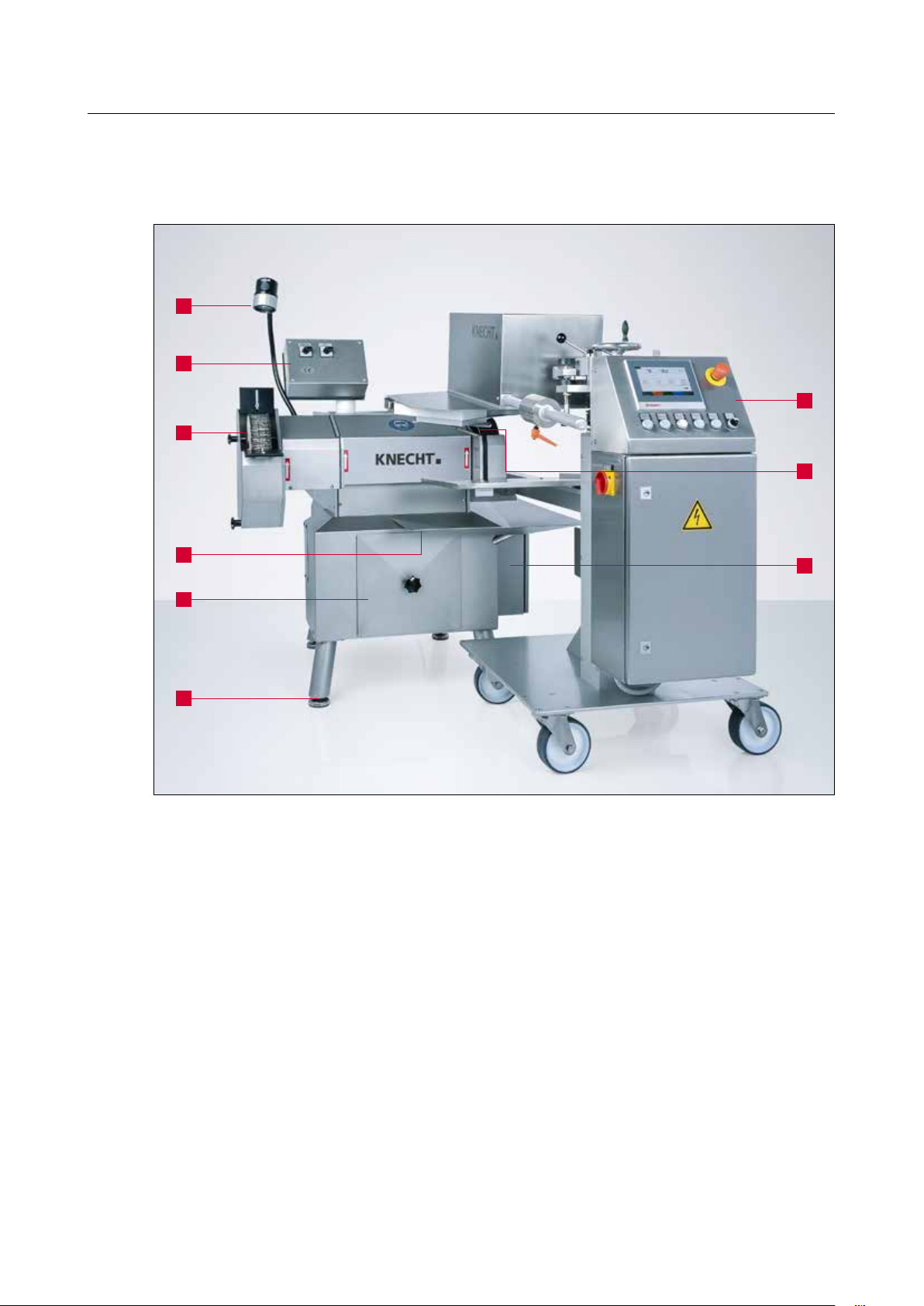
3.4 Description of components
1
2
3
7
8
4
5
6
Figure 3-2 Overall view of automatic grinding machine
1 Work light
2 Control panel for USK 230 B
3 Finned brush
4 Water tray
5 Water tank
6 Machine feet
7 Control panel for HV 208 copy grinding device
8 Wet-grinding belt
9 Toolbox
9
17
Page 17
3. Description
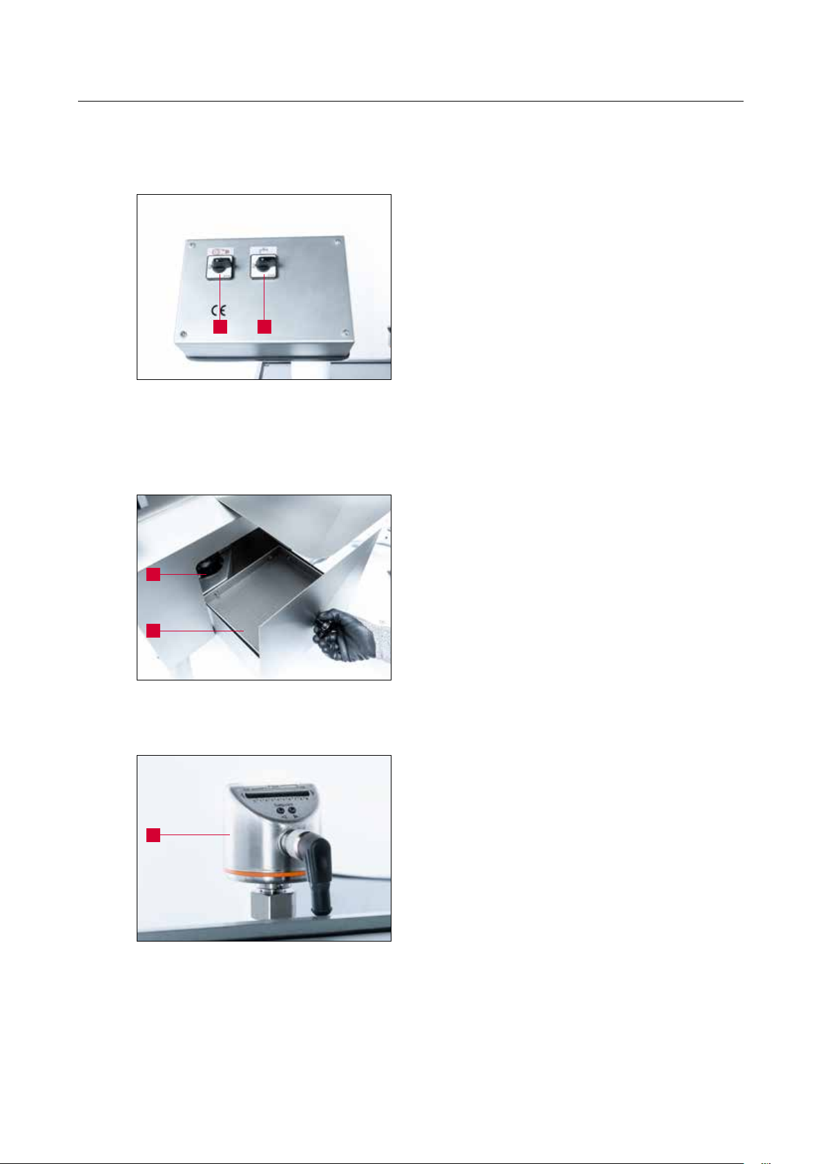
3.4.1 USK 230 B control panel
1 2
Figure 3-3 Control panel
3.4.2 Coolant unit
1 Wet-grinding belt ON / OFF
2 Coolant pump ON / OFF
1
2
Figure 3-4 Coolant unit
1
1 Coolant pump
2 Water tank
The grinding machine has a flow gauge (3-5/1)
which automatically interrupts the program flow if
there is no coolant flow.
The flow gauge is located on the top side of the
machine and must be cleaned regularly.
18
Figure 3-5 Flow gauge
Page 18
3. Description
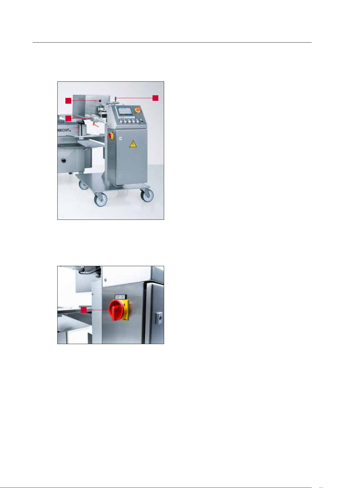
3.4.3 HV 208 copy grinding device
1
2
1 Locking lever
2 Balance weight
3
3 Handwheel to set grinding angle
Figure 3-6 HV 208 copy grinding device
3.4.4 Switching the copy grinding device on / off
The main switch (3-7/1) is located on the left side
of the copy grinding device.
Turning the main switch from “0” to “I” switches
on the copy grinding device.
1
Figure 3-7 Copy grinding device main switch
Turning the main switch from “I” to “0” switches
off the copy grinding device.
19
Page 19
3. Description
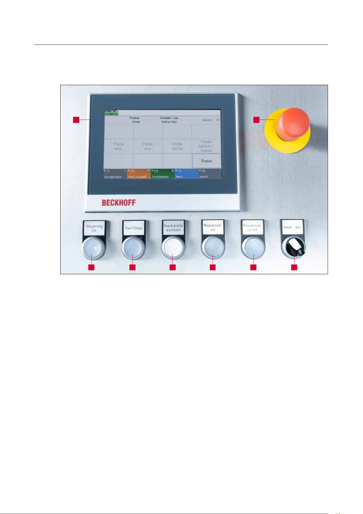
3.4.5 HV 208 control panel
1 2
Figure 3-8 Control panel
1 Touch panel
2 “Emergency off” button
3 “Control ON” button: Activates controls (when button flashing)
4 “Start / Stop” button: Starts grinding program
5 “Change copy plate” button: manually runs the copy grinding plate
6 “Knife feed forward” button: Drive knife up to wet-grinding belt
7 “Knife feed back” button: Drive knife back from wet-grinding belt
8 “Manual / Automatic” selector switch
876543
20
Page 20

3. Description
3.4.6 Layout of user interface (main screen)
1
2
3 4 5 6
8 9 10 11 12
Figure 3-9 Main screen
1 “Product”: display of selected product file
2 “Step”: display of current program step
3 “Copy grinding plate left”: run copy grinding plate to the left
4 “Copy grinding plate off”: switch off copy grinding plate
5 “Copy grinding plate right”: run copy grinding plate to the right
6 “Lower / lift copy grinding plate”: lift / lower copy grinding plate
7 “Reset”: delete temporary error messages
8 “F1 Home position”: run copy grinding plate to initial position
9 “F2 Prod. selection”: select product files
10 “F3 Product data”: change product data parameter
11 “F4 Menu”: configure settings and language of user interface
12 “F5 back”: return to previous display
7
NOTICE
The button assignments vary according to the
current display screen. The respective assignment is indicated in text form.
21
Page 21

3. Description
3.4.7 SP 110 copy grinding plate
1
Figure 3-10 SP 110 copy grinding plate
The knives are clamped onto a copy grinding plate
(3-10/1) for machining.
A matching copy grinding plate is needed for each
blade shape and size. Knives may only be ground
using the SP 110 copy grinding plate.
Copy grinding plates for new knife types can be
obtained from KNECHT Maschinenbau GmbH on
request.
22
Page 22

4. Transport
When transporting, observe the local applicable safety and accident
prevention regulations.
Transport the grinding machine with the machine feet facing downwards.
CAUTION
4.1 Means of transport
For transporting and for setting up the grinding machine, only use adequately dimensioned
transport aids, e.g. truck, forklift or hydraulic lifting truck.
When using a forklift or a lifting truck, move the fork under the grinding machine.
Note the machine’s center of gravity when transporting. The center of gravity (CoG) is shown in
Figure 3-1.
4.2 Transport damage
If damage is detected upon unloading after the delivery is accepted, inform KNECHT Maschinenbau GmbH and the freight forwarder immediately. Refer directly to an independent specialist as
needed.
Remove the packaging and shipping straps. Remove the shipping straps on the grinding machine.
Dispose of packaging in an environment-friendly manner.
4.3 Transport to another installation site
For transport to another installation site, ensure that the space requirements are fulfilled (see
chapter 3.2).
A permissible electrical connection must be provided at the new installation site.
The grinding machine must sit tightly and securely.
Work on the electrical unit is only to be carried out by an authorized
specialist or one of our customer service representatives. Observe the
local applicable safety and accident prevention regulations.
CAUTION
23
Page 23

5. Installation
5.1 Selection of qualified personnel
We recommend having maintenance work on the grinding machine
carried out by trained KNECHT personnel.
We are not liable for any damage resulting from improper installation.
CAUTION
5.2 Installation site
When determining the installation site, bear in mind the space required for installation as well as
maintenance and repair work on the grinding machine (see chapter 3.2).
5.3 Supply connections
The grinding machine is provided with the corresponding connection cable.
Confirm that the machine is correctly connected to the current supply.
CAUTION
5.4 Settings
KNECHT Maschinenbau GmbH will configure the various components as well as the electrical
system before delivery.
ATTENTION
Unauthorized changes to the preset values
are not permitted and can damage the
grinding machine.
24
Page 24

5. Installation
5.5 Initial start-up of the grinding machine
Place the grinding machine at the installation site on a level base.
Compensate for any unevenness in the floor using the adjustable machine feet by unscrewing
them counterclockwise. The machine is aligned using a level.
Have an authorized electrician install the current supply on-site.
Completely install and inspect the protective equipment before commissioning.
Have all protective equipment checked for proper functioning by
authorized trained personnel before commissioning the machine.
CAUTION
Have the compressed air supply installed on site by a qualified technician.
Confirm that the machine is correctly connected to the pressurized air
supply.
If connected incorrectly, pressurized air may leak, causing parts to spin
CAUTION
and potentially injure someone.
Observe local safety and accident prevention regulations for pressurized
air.
25
Page 25

6. Commissioning
All work on the machine may only be performed by trained personnel.
Observe the local applicable safety and accident prevention regulations.
CAUTION
Figure 6-1 Filling the water tank
Connect phase inverter plug with the on-site outlet (3x 400 V, 16 A).
Turn “Wet-grinding belt” switch (3-3/1) to “ON” position. The wet-grinding belt and finned brush
will start rotating.
There is a risk that hands, hair, and clothing may be pulled in while the
grinding machine is switched on.
Serious injury may result. Wear personal protective equipment.
1
Fill water tank (6-1/1) with approx. 15 liters of
water.
1
Figure 6-2 Checking the direction of rotation
Check the direction of rotation of the finned
brush.
The direction arrow (6-2/1) indicates the direction
of rotation of the wet-grinding belt / finned brush.
If the finned brush is rotating in the right direction, then the wet-grinding belt is also rotating in
the correct direction.
If the direction is rotating in the wrong direction,
have the phase reversed by a qualified electrician.
Switch off the grinding machine.
26
Page 26

6. Commissioning
1
Insert plug for the copy grinding device into the
USK 230 grinding machine.
3
Figure 6-3 Mounting the copy grinding device
Figure 6-4 Distance of knife to wet-grinding
belt
2
3
Completely install and inspect the protective
equipment before commissioning.
Attach copy grinding device spacer block (6-3/1)
using a hex key.
Then attach the clamping arm (6-3/2) of the
HV 208 with the star handles (6-3/3) on the spacer
block.
When calibrating the angle scale, a copy grinding
plate is inserted into the machine with the corresponding knife.
Switch on the grinding machine.
Switch on copy grinding device using the main
switch (3-7/1) and release “Emergency off” button (3-8/2).
Set the “Manual / Automatic” selector switch (38/8) to “Automatic” and press the “Start / Stop”
button (3-8/4).
Check distance between wet-grinding belt and
copy grinding plate. A distance of 6 mm is necessary for a grinding angle of 25°.
After presetting to approx. 6 mm, set the
“Manual / Automatic” selector switch (3-8/8) to
“Manual” and mount a new wet-grinding belt.
Set the “Manual / Automatic” selector switch
(3-8/8) to “Automatic” and press the“Start / Stop”
button (3-8/4). A bevel will now be ground onto
the knife.
After the program ends, release the knife and
measure the ground angle with the protractor
provided.
27
Page 27

6. Commissioning
1
Figure 6-5 Clamping lever angle scale
Set the measured angle on the angle scale.
To do so, loosen the clamping lever (6-5/1) and
push the angle scale (6-6/1) up in height until the
measured angle is set.
Retighten the clamping lever (6-5/1).
Then set the desired angle using the “Set grinding
angle” handwheel (6-6/2). Grind the knife again
and check the angle.
Readjust the scale again as needed.
2
Figure 6-6 Angle scale
Switch off copy grinding device and grinding
machine.
1
28
Page 28

7. Operation
7.1 General grinding fundamentals
If a cutting edge has become dull, material must be removed in order to reach its original
sharpness.
To do so, the respective knife is ground to the cutting edge. While doing so, if a burr is created
on the cutting edge, then the grinding process is complete and can be finished. Before creating
the final sharpness, the resulting burr must be removed as part of an additional step. This is done
with a finned brush.
As it is not only the sharp cutting edges but also the long service lives that define a blade, the
cutting edge angle is another important indicator of a blade's performance. The smaller the
cutting edge angle, the higher its theoretical service life. In practice, however, it seems that a
cutting edge angle that is too small results in the cutting edge breaking off and thus becoming
dull.
The cutting edge angle is therefore between 15° and 35°. For cutting edge angles below 15°, the
cutting edge is so unstable that it snaps with the smallest resistance. For a cutting edge angle of
more than 35°, the cutting edge angle is extremely stable, but this does reduce the service life.
The cutting edge profile is an additional criterion for the characteristics of the cutting edge.
There are three different ground surfaces:
Tapered ground surface Convex ground surface Concave ground surface
Convex ground surfaces can mostly be found on cutter blades and hand knives. Tapered and
concave ground surfaces are predominantly found on circular knives and blades.
In essence: The profile and cutting edge angle stipulated by the manufacturer must be
maintained.
29
Page 29

7. Operation
For all work on / with the machine, the locally applicable safety and
accident prevention regulations as well as instructions in the “Safety”
and “Important notes” sections of the operating instructions must be
observed.
CAUTION
7.2 Switching on the copy grinding device
Switch the main switch (3-7/1) of the copy grinding device to the “I” position. The “Emergency
off” button (3-8/2) must be released.
Wait for the controls to initialize. The main screen will appear.
Press the “Control ON” (3-8/3) switch. The control is now activated.
Set the “Manual / Automatic” selector switch (3-8/8) to “Manual”.
7.3 Grinding the cutter knife
7.3.1 Mounting the copy grinding plate
1
Figure 7-1 Moving the copy grinding device
into change position
1
To clamp on the knife, swivel the drive unit to the
change position.
Loosen the locking slide of the copy grinding device with the locking lever (7-1/1) and swivel the
drive unit to the right using the balance weight
guide rod (3-6/2).
Push the copy grinding plate (7-2/1) onto the
guide carriage ball bearings (7-2/2) to the stop
and press against the stop with the right hand.
30
2
Figure 7-2 Mounting the copy grinding plate
Hold the “Change copy grinding plate” button
(3-8/5) until the copy grinding plate has moved
2 - 3 cm.
Page 30

7. Operation
With the pin in front, push the limit switch cam
(7-3/1) under the copy grinding plate and tighten
the star handle (7-3/2).
2
1
Figure 7-3 Mounting the limit switch cam
ATTENTION
The cam defines the end of the travel path and
triggers movement in the opposite direction.
If the cam is not attached for the end
position, the copy grinding plate will move
down from the guide carriage and may fall
off and become damaged.
Place knife (7-4/1) on the mounting for the copy
grinding plate and turn latch (7-4/2) onto knife.
1
2
Figure 7-4 Clamping the cutter knife
Risk of injury on the chain sprocket; fingers, hair, and clothing may
become entangled.
Sharp cutting edges. Serious cutting injuries may result!
CAUTION
Wear protective gloves.
31
Page 31

7. Operation
1
Figure 7-5 Swiveling the copy grinding device
to working position
ATTENTION
Swivel the drive unit into the work position and
lock the locking slide (7-5/1) of the copy grinding
device using the locking lever (7-1/1).
Check whether the copy grinding plate is
suitable for the knife before grinding the
knife. (Compare the label of the copy grinding plate with that of the knife). The use of
an unsuitable copy grinding plate can damage the knife and copy grinding plate.
NOTICE
7.3.2 Setting the balance weight
1
2
Figure 7-6 Mounting the copy grinding plate
There is a suitable copy grinding plate for
each type of cutter knife. KNECHT requires a
sketch of the knife or a new knife in order to
manufacture the grinding plate. If possible,
specify the cutter type, blade radius and knife
type.
The balance weight (7-6/1) is used to balance the
decreasing aggressiveness of the wet-grinding belt
due to wear by increasing the grinding pressure.
The farther the balancing weight is from the
wet-grinding belt, the lower the grinding pressure
3
will be.
The closer the balancing weight is to the grinding
belt, the higher the grinding pressure will be.
The balancing weight (7-6/1) is fixed to the guide
rods (7-6/3) using the clamping lever (7-6/2).
32
Page 32

7. Operation
7.3.3 Setting the grinding angle
Set the grinding angle with the handwheel
(7-7/2).
2
1
Figure 7-7 Setting the grinding angle
7.3.4 Switching on the USK 230 grinding machine
The grinding angle is read on the scale (7-7/1) at
the point at which it leaves the machine housing.
1
Figure 7-8 Control panel USK 230
2
7.3.5 Starting the grinding process
Set the switch for the wet-grinding belt (7-8/1)
and the coolant pump (7-8/2) to “I” on the
USK 230 control panel.
The wet-grinding belt and finned brush will start
rotating and the coolant pump is switched on.
Set the copy grinding device to “Automatic” using
the “Manual / Automatic” selector switch (7-9/4).
Select desired grinding program (see chapter 8.2)
and press “Start / Stop” button (7-9/1).
Figure 7-9 Control panel
41 32
If the wet-grinding belt and coolant pump are not
running, switch them on as described in chapter
7.3.4.
Press the “Start / Stop” button (7-9/1) again.
The copy grinding plate will run to its initial
position and lower to the wet-grinding belt. The
“Start / Stop” button (7-9/1), “Knife feed forward”
button (7-9/2), and “Knife feed back” button (79/3) will flash.
33
Page 33

7. Operation
Using the “Knife feed forward” button (7-9/2),
run the copy grinding plate to the wet-grinding
belt until a grinding noise can be heard.
Press the “Start / Stop” button (7-9/1). The grinding program will start.
After completing the grinding process, the copy
grinding plate will again run to its initial position.
1
Figure 7-10 Polishing / deburring the cutter
knife
Sharp cutting edges.
Serious cutting injuries may result.
CAUTION
Remove knife and polish and deburr on the finned
brush (see chapter 7.5).
After the second knife, only press the
“Start / Stop” button (7-9/1) to start the grinding
process. There is no need to press manually.
34
Page 34

7. Operation
7.3.6 Canceling the grinding process
1
Figure 7-11 Canceling the grinding process
By pressing the “Start / Stop” button (7-11/1), the
program can be canceled at any time in order to,
for example, check the resulting burr on the knife.
Pressing the “Start / Stop” button (7-11/1) again
allows the user to restart. The machine will continue the grinding process at the location where it
was stopped.
35
Page 35

7. Operation
7.4 Replacing the copy grinding plate
Never change the copy grinding plate when the knife is clamped.
There is a rick of becoming crushed and entangled in the drive pinion.
CAUTION
1
2
Figure 7-12 Changing the copy grinding plate
Serious injury may result.
Press the “Change copy grinding plate” button (3-8/5) only when the
copy grinding plate is mounted.
Loosen the star handle (7-12/1).
Remove limit switch cam (7-12/2).
Set the “Manual / Automatic” selector switch (713/2) to “Manual” and hold the “Change copy
plate” button (7-13/1) until the copy grinding
plate can move no further.
36
Figure 7-13 Control panel
The direction in which the copy grinding plate is
21
moving can be changed by repeatedly pressing
the “Change copy plate” button (7-13/1).
Allow the plate to run endlessly right. Release the
button after the copy grinding plate has run completely out; the drive will stop immediately.
Remove copy grinding plate manually without
tilting drive pinion and store carefully.
Lay the new copy grinding plate onto the drive
pinion, press the “Change copy plate” button
(7-13/1) and hold until the copy grinding plate is
approximately in the middle.
With the pin in front, push the limit switch cam
(7-12/2) under the copy grinding plate and tighten
the star handle (7-12/1).
Page 36

7. Operation
The copy grinding plate has now been changed.
The copy grinding plate does not have to be in a
defined position to start automatically.
If the stop for the copy grinding plate is attached
on the right, it can be moved to the left and right
in manual mode by pressing the “Change copy
plate” button (7-13/1).
Pressing the button again will change the
direction.
NOTICE
If the copy grinding plate is not fed in
correctly, push it back by hand.
37
Page 37

7. Operation
7.5 Deburr cutter knife with the finned brush
There is a risk that hands, hair, and clothing may be pulled in while the
grinding machine is switched on.
Never hold the cutting edge against the rotation direction of the finned
CAUTION
brush.
Polishing gives rise to grinding particles that could enter the eyes. Wear
safety glasses. Wear a face mask.
Serious injury may result!
1
Figure 7-14 Polishing / deburring the cutter
knife
The burr created on the knife during the grinding
process is removed by the finned brush. This will
help the cutter knife retain its final sharpness.
Hold the polishing paste briefly against the running finned brush before the polishing / deburring
process.
To polish / deburr cutter knifes, unclamp from the
grinding device and run along the finned brush
(7-14/1) at a steep angle.
Alternately polish the upper and lower side of the
knife until the burr is removed.
38
Page 38

7. Operation
7.6 Grinding hand knives on the wet-grinding belt
There is a risk that hands, hair, and clothing may be pulled in while the
grinding machine is switched on.
Never hold the cutting edge against the rotation direction of the
CAUTION
wet-grinding belt. Serious injury may result!
1
Figure 7-15 Grinding hand knives
1
Lay the hand knife flat onto the wet-grinding belt
(7-15/1).
The cutting edge should run an angle to the
grinding belt, not perpendicular. Press the knife
onto the grinding belt with your free hand. The
stronger the pressure, the more convex the grind
will be.
Pull both sides of the hand knife over the grinding belt alternately until a burr is created over the
entire cutting edge length.
The burr on the knife is removed at the finned
brush (7-16/1). This will help the hand knife retain
its final sharpness.
Both sides of the knife blade are honed alternately
on the finned brushes.
Figure 7-16 Polishing hand knives
39
Page 39

7. Operation
7.7 Changing the wet-grinding belt
For all work on the grinding machine, the locally applicable safety and
accident prevention regulations as well as instructions in the “Safety”
and “Important notes” section of the operating instructions must be
observed.
CAUTION
Loosen and remove both star handles (7-17/1) by
turning them counter-clockwise and remove belt
protection hood.
1 1
Figure 7-17 Opening the belt protection hood
1
Figure 7-18 Belt release lever
Do not switch on grinding machine when belt protection hood is
removed!
Turn the belt relief lever (7-18/1) in the direction
of the arrow up to limit stop.
40
Serious injury may result!
CAUTION
Page 40

7. Operation
ATTENTION
Remove the used wet-grinding belt and place a
new belt over the contact disc and guide pulley.
Turn the belt relief lever (7-18/1) against the direction of the arrow up to limit stop.
Turn the wet-grinding belt by hand and check to
see if it is not grinding anywhere.
Mount the belt protection hood.
Heed the running direction arrows on the
inside of the grinding belt!
Only original grinding belts approved by
KNECHT Maschinenbau GmbH may be used.
7.7.1 Belt adjustment
1
Figure 7-19 Belt adjustment
Incorrect grinding belts can result in overheated cuts that cause the knife to break.
If the grinding belt is not running in the center of
the contact disc, it can be aligned with the belt
adjustment (7-19/1).
Turning the belt adjuster (7-19/1) counter-clockwise makes the grinding belt run to the left.
Turning the belt adjustment (7-19/1) clockwise
makes the grinding belt run to the right.
41
Page 41

7. Operation
7.8 Replacing the finned brush
To change the finned brushes, turn the star handles (7-20/1) counter-clockwise.
1
1
Figure 7-20 Changing the finned brush
ATTENTION
Do not switch on the machine with the protection hood is removed!
Then remove the guard carefully and clean as
necessary.
Loosen the nut with the included flat wrench,
carefully pull the old finned brush downwards,
and replace with a new one.
Then mount the complete guard again in reverse
order.
Verify that all parts are functioning properly!
Only original finned brushes approved by
KNECHT Maschinenbau GmbH may be used.
Incorrect finned brushes can damage the
blades.
CAUTION
Serious injury may result!
42
Page 42

8. Control
8.1 Main screen
1
3 4 5 6
2
8 9 10 11 12
Figure 8-1 Main screen
1 “Product”: display of selected product file
2 “Step”: display of current program step
3 “Copy grinding plate left”: run copy grinding plate to the left
4 “Copy grinding plate off”: switch off copy grinding plate
5 “Copy grinding plate right”: run copy grinding plate to the right
6 “Lower / lift copy grinding plate”: lift / lower copy grinding plate
7 “Reset”: delete temporary error messages
8 “F1 Home position”: run copy grinding plate to initial position
9 “F2 Prod. selection”: select product files
10 “F3 Product data”: change product data parameter
11 “F4 Menu”: configure settings and language of user interface
12 “F5 back”: return to previous display
7
43
Page 43

8. Control
8.2 Selecting product files
A specific product file is saved for every grinding
task. This product file must be selected and loaded
before grinding in automatic mode.
This is done as follows:
1
Figure 8-2 Main screen
Figure 8-3 Selecting product file
Press “F2 Prod. selection” (8-2/1) on the touch
panel. A new window (8-3) will open.
Select the required product file; it will be underlined in blue.
Load the product file to the controller via the
“F4 Activate” (8-3/1) touch panel button.
1
1
The program will switch back automatically to the
main screen.
The new product file will appear on the “Product”
line (8-4/1). The new parameters are now loaded
by the controller.
44
Figure 8-4 Main screen
Page 44

8. Control
8.3 Renaming, creating, and deleting product files
Product files can be renamed, deleted, and
recreated via copying.
This is done as follows:
Press “F2 Prod. selection” (8-5/1) on the touch
1
Figure 8-5 Main screen
panel.
A new window (8-6) will open.
Select the required product file; it will be underlined in blue.
Figure 8-6 Editing product file
8.3.1 Renaming product file
1
2
Figure 8-7 Renaming product file
Select the corresponding field on touch panel:
“F1 Rename” (8-6/1), “F2 Delete” (8-6/2), or
“F3 Copy” (8-6/3).
4 51 2 3
If “F1 Rename” (8-6/1) is pressed, the image
to the left will open (8-7).
Edit file name (8-7/1) with the keyboard and
confirm with “OK” (8-7/2).
The window will close. The renamed file will
appear in the product file directory.
Then select a product file with “F4 Activate”
(8-6/4) or return to the main screen with
“F5 back” (8-6/5).
45
Page 45

8. Control
8.3.2 Renaming product file
1
2
Figure 8-8 Creating product file
8.3.3 Deleting product file
2
Figure 8-9 Deleting product file
If “F3 Copy” (8-6/3) is pressed, the image to the
left will open (8-8).
Edit file name (8-8/1) with the keyboard and
confirm with “OK” (8-8/2).
The window will close. The new file will appear in
the product file directory.
Proceed as described in chapter 8.4 to edit the
product file parameters.
If “F2 Delete” (8-6/2) is pressed, a popup window
(8-9/1) will open.
Confirm with “Yes” (8-9/2), cancel with “No”.
1
The popup window will close.
43
Then select a product file with “F4 Activate” (89/3) or return to the main screen with “F5 back”
(8-9/4).
46
Page 46

8. Control
8.4 Editing product file parameters
The parameters of a product file can be changed
as follows:
Press the “F3 Product data” touch panel field
(8-10/1) on the main screen.
1
Figure 8-10 Main screen
1
Figure 8-11 Parameter groups
A new window (8-11) will open.
“Grinding” (8-11/1): Grinding process data (see
chapter 8.4.1)
The active group is always shown with a green
arrow. A group is activated by pressing on the
name. The arrow will jump again and the group
underlined in blue.
47
Page 47

8. Control
8.4.1 Meaning of the “Grind” parameter
1
2
3 4
Figure 8-12 “Grinding” parameter
1 “Correction value grinding return”: The positioning time of the cycle times will be added
up and provides the basis for the return time. In order to compensate for imprecision, a
correction value on the return time for return runs is entered when changing segments.
The correction value is added to the total lead time.
2 “Disable knife feed during left move”: true = reset knife feed disabled, false = reset knife
feed enabled
To change the parameter, tap on the respective field highlighted in yellow. The window (8-13)
opens for “Number”, the window (8-14) for “Values”.
Select the desired number and confirm with “OK”
(8-13/1).
48
The touch panel field “Cancel” closes the window
without recording the number.
1
Figure 8-13 Editing “Number” parameter
Page 48

8. Control
1
Figure 8-14 Editing the “Values” parameter
ATTENTION
Choose between “true” and “false” for values
and confirm with “OK” (8-14/1).
The touch panel field “Cancel” closes the window
without recording the value.
Save the changed value with the touch panel
field “F2 Save” (8-12/4).
If a current product file is changed, overwrite
via the “F1 Activate” (8-12/3) touch panel
control.
49
Page 49

8. Control
8.4.2 Meaning of the “Feed Cycles” parameter
1
2
3 4
Figure 8-15 “Feed Cycles” parameter
1 “Number of grinding cycles per feed”: Grinding cycles in the respective step; if the value is
“0”, the step will not be carried out
2 “Feed after all grinding cycles”: Distance traveled by the knife after completing the respec-
tive step and moving to the next (in mm)
NOTICE
To change the parameter, tap on the respective field highlighted in yellow. The window (8-16)
opens for “Number”.
The aforementioned parameters are related
to steps 2 - 10.
50
Select the desired number and confirm with “OK”
(8-16/1).
The touch panel field “Cancel” closes the window
without recording the number.
1
Figure 8-16 Editing “Number” parameter
Page 50

8. Control
ATTENTION
Save the changed value with the touch panel
field “F2 Save” (8-15/4).
If a current product file is changed, overwrite
via the “F1 Activate” (8-15/3) touch panel
control.
51
Page 51

8. Control
8.5 Machine data
The machine data is accessed via the main menu “F4 Menu” (8-1/11), to “F4 Options”, and then
“F1 Machine Data”. The “Machine Data” display (8-17) shows the basic machine settings. The
data are saved in a file and can be loaded again from the file.
1 2 3 4
Figure 8-17 Machine data
1 “F1 Activate”
2 “F2 Save”
3 “F4 File Dialog”
4 “F5 back”: return to previous display
8.5.1 Grinding
1
2
1 “Delay for touching position after
segment change”: (in s)
2 “Timeout knife base search”: (in s)
52
Figure 8-18 Machine data “Grinding”
Page 52

8. Control
8.5.2 Coolant controls
1
Figure 8-19 Machine data “Coolant flow control”
8.5.3 Settings
1
2
3
1 “Coolant flow controls disabled”:
true = coolant flow controls disabled,
false = coolant flow controls enabled
1 “Copy grinding plate tilt time”: Hold time
for lowering the copy grinding plate (in s)
2 “Timeout if copy grinding plate stand
still”: (in s)
3 “Timeout cam search”: (in s)
Figure 8-20 Machine data “Settings”
53
Page 53

8. Control
8.6 Language
Figure 8-21 Main screen
The user interface language can be changed to
the language of the country of use.
Press “F4 Menu” (8-21/1) on the touch panel to
return to the menu.
1
Press “F1 Language” (8-22/1) on the touch panel.
A new window (8-23) will open.
1 2
Figure 8-22 Start screen
1
Figure 8-23 Selecting language
The desired language is selected and automatically
activated by pressing the corresponding touch
panel button (8-23/1).
Then press “F5 back” (8-23/2) on the touch panel
to return to the menu (8-22).
2
The main screen appears by pressing “F5 back”
(8-22/2).
54
Page 54

8. Control
8.7 Setting up an internet connection
The machine has a network connector (8-24/1)
with which a direct connection between the ma-
1
Figure 8-24 Control cabinet
chine and KNECHT Maschinenbau can be made.
The connection allows the display screen content
on the grinding machine to be transmitted. In this
way, the manufacturer's technicians can perform
a diagnosis of the machine, change software settings and install or edit new grinding programs.
“Team Viewer”, the program pre-installed on your
machine, is required in order to set up the internet
connection. An active internet connection must be
available.
Please use the network cable provided with the
on-site network socket and connect the network
connector (8-24/1) in the control cabinet.
NOTICE
Please have the internet connection established by your network administrator.
55
Page 55

9. Care and maintenance
For all work on the grinding machine, the locally applicable safety and
accident prevention regulations as well as instructions in the “Safety”
and “Important notes” section of the operating instructions must be
observed.
CAUTION
9.1 Cleaning
Clean the grinding machine and copy grinding device each time after sharpening to prevent the
grinding sludge from drying, hence making it harder to remove. There is a wash brush on the rear
side of the grinding machine for this.
After cleaning, lightly grease the grinding machine and copy grinding device with non-corrosive
oil. See also the lubrication schedule, chapter 9.2.1.
The coolant must be replaced on a weekly basis, and the container must also be cleaned.
ATTENTION
9.2 Lubrication and maintenance
1
2
Figure 9-1 Flow gauge
Do not spray-wash the grinding machine
with water. This can damage the grinding
machine!
The finned brush does not work when wet.
The flow gauge (9-1/1) must be removed and
cleaned 1x monthly.
To do so, disconnect the plug (9-1/2) and turn the
flow gauge counter-clockwise by hand using a hex
key. Clean the measuring probe with a clean cloth.
Lubricate the threading slightly (not the probe)
and rotate back down.
Installation is carried out in the opposite direction.
56
Page 56

9. Care and maintenance
9.2.1 Lubrication schedule and lubricant table
Lubrication work Cycle OEST SHELL EXXON Mobil
Lubricate thread of star
handles, clamping lever,
and flow gauge
Oil machine parts after
cleaning
4 weeks L2 multipurpose
grease
After each
grinding
Paraffinum
Perliquidum 16L
Gadus
S2 V 100 2
Shell Risella 917 Marcol 82
Mobilith
SHC 100
57
Page 57

10. Malfunctions
10.1 Malfunctions
Malfunctions Error Remedy
The knife is not taking on an
edge
The knife is burning No coolant is reaching onto
Wet-grinding belt stops under
load
Wet-grinding belt moves violently
backwards and forwards or
cannot be adjusted
Wet grinding belt is dull Install new wet-grinding belt
Grinding angle is set incorrectly
Grinding cycles set too low Set higher number (see chapter 8.4.2)
Grinding angle on knife Use new wet-grinding belt
Grinding pressure too low Push weight forward
the wet-grinding belt
Wet grinding belt too coarse Mount finer wet-grinding belt
V-belt tension too weak Tighten V-belt
V-belt and V-pulley worn Replace V-belt and V-pulley
Wet-grinding belt faulty Install new wet-grinding belt
Contact disc is damaged or
worn out
Guide pulley is worn out Install new guide pulley
Set the angle (see chapter 7.3.3) or
adjust the scale (see chapter 6)
Fill / clean the coolant supply for the
grinding machine
Install new contact disc
“Coolant error” message on the
main screen
Grinding machine cannot be
switched on
Attachment does not lower onto
the grinding belt after being
switched on
Attachment “whistles” during
operation
Attachment tips from side to side
very quickly
Too little coolant in the coolant tank
Lines are blocked Clean lines
Pump defective Replace pump
Flow gauge is dirty Clean flow gauge
Motor protection switch has
tripped
Pressurized air not connected Connect pressurized air hose
Pressurized air set too low Set pressure regulator to 6.5 bar
Limit switch cam rubs on the
protective cover
Shock absorber defective Install new shock absorber
Fill coolant
Switch on the motor protection switch
Lubricate limit switch cam or protective
cover
If a malfunction is not included in the malfunction table or if you cannot rectify the malfunction,
please contact our customer service (chapter 12).
58
Page 58

11. Disassembly and disposal
11.1 Disassembly
Dispose of all operating materials properly.
Secure moving parts against slippage.
Disassembly must be conducted by a qualified specialist.
11.2 Disposal
After the machine has reached the end of its service life, it must be disposed of by a qualified
specialist. In certain situations, and after consultation with KNECHT Maschinenbau GmbH, the
machine may be returned.
Operating materials (e.g. grinding belts, finned brushes, coolants etc.) must also be disposed of
correctly.
59
Page 59

12. Service, spare parts and accessories
12.1 Postal address
KNECHT Maschinenbau GmbH
Witschwender Straße 26
88368 Bergatreute
Germany
Telephone +49 -7527-928-0
Fax +49 -7527-928-32
mail@knecht.eu
www.knecht.eu
12.2 Service
Service line:
For address, see postal address
service@knecht.eu
12.3 Spare parts
If you are in need of spare parts, please use the spare parts list provided with the machine. Please
make your order using the format provided in the following.
When ordering, please always provide: (Example)
Machine type (USK230B-HV208II)
Machine number (2381065230B)
Component designation (water tank)
Designation of individual part (submersible pump)
Item no. (12)
Drawing no. (410FA01-0594)
Quantity (1)
We are always happy to answer any questions.
60
Page 60

12. Service, spare parts and accessories
12.4 Accessories
12.4.1 Abrasives used, etc.
Designation Dimensions Grain Order number Note
Wet-grinding belt 2200x60 80 412A-62-0725
2200x60 100 412A-63-0726
2200x60 120 412A-64-0727
2200x60 240 412A-66-0728
Wet-grinding belt,
compact grain
Finned brush d.340x60xd.25 412J-04-0509 Installed on
Polishing paste 1200 g 412R-01-0501 Included in
ATTENTION
If you require wet-grinding belts, finned brushes, polishing pastes or other accessories, please
contact our sales staff, partners, or KNECHT Maschinenbau GmbH directly.
Thank you for choosing KNECHT!
2200x60 180 412A-70-0180 Installed on
delivery
delivery
delivery
Do not use any other abrasives without the
approval of KNECHT Maschinenbau GmbH.
KNECHT Maschinenbau GmbH is not liable in
the event that other abrasives are used.
61
Page 61

13. Annex
13.1 EC Declaration of Conformity
in accordance with the EC Directive 2006 / 42 / EC
• Machinery Directive 2006 / 42 / EC
• Electromagnetic Compatibility Directive 2014 / 30 / EC
We hereby declare that the machine designated as follows, due to its construction and design as
well as the version we sell, complies with the relevant basic safety and health requirements of the
applicable EC Directive.
If the machine is modified in a manner that we did not condone, this declaration shall no longer
be valid.
Designation of the machine: Automatic grinding Machine
Model designation: USK 230 B - HV 208 II
Applicable harmonized standards, DIN EN ISO 12100:2011
especially: DIN EN ISO 13857:2008
DIN EN ISO 16089:2016
DIN EN 61000-3-2:2015
DIN EN 61000-3-3:2014
DIN EN 55014-1:2012
DIN EN 349:2008
Responsible for documentation: Peter Heine (B. Eng. Mechanical Engineering BA)
Tel. +49 -7527-928-15
Manufacturer: KNECHT Maschinenbau GmbH
Witschwender Straße 26
88368 Bergatreute
Germany
Technical documentation is available and complete. The operating instructions document for the
machine is available in its original version and in the native language of the user.
62
Bergatreute, August 12, 2019 Managing Director
–––––––––––––––––––––––––– –––––––––––––––––––––––––– ––––––––––––––––––––––
Place, date Signature Signatory details
Page 62

KNECHT Maschinenbau GmbH
Witschwender Straße 26
mail@knecht.eu
■ 88368 Bergatreute ■ Germany ■ T + 49
■ www.knecht.eu
-
7527- 928-0 ■ F + 49 -7527- 928-32
 Loading...