

Page 1

Operating Instructions
Status 08.2018 ■ Version 1.3 | Translation
A 950 II
Grinding Machine for Sickle-shaped and Circular Knives
Page 2

Operating Instructions
Grinding Machine for Sickle-shaped and Circular Knives A 950 II
Manufacturer
KNECHT Maschinenbau GmbH
Witschwender Straße 26
88368 Bergatreute
Germany
Phone +49 -7527-928-0
Fax +49 -7527-928-32
mail@knecht.eu
www.knecht.eu
Documents for the machine operator
Operating instructions
Date of issue of the operating instructions
August 22, 2018
Copyright
The copyright for these operating instructions and documents is held by KNECHT Maschinenbau GmbH.
These documents will be delivered only to our customers and to operators of our products and are a part of
the machine.
These documents may neither be reproduced, nor made accessible to third parties, including rival firms,
without our express permission.
3
Page 3

Table of contents
1. Important notes 7
1.1 Preface to the operating instructions 7
1.2 Warnings and symbols in the operating instructions 7
1.3 Warning signs and what they mean 8
1.3.1 Warning and prohibition signs on the grinding machine 8
1.3.2 General prohibitions signs 8
1.4 Rating plate and serial number 9
1.5 Figure and item numbers in the operating instructions 10
2. Safety 11
2.1 Basic safety instructions 11
2.1.1 Observe notes in the operating instructions 11
2.1.2 Obligation on the part of the operator 11
2.1.3 Obligation on the part of the personnel 11
2.1.4 Hazards involved in handling the grinding machine 11
2.1.5 Malfunction 12
2.2 Intended use 12
2.3 Warranty and liability 12
2.4 Safety regulations 13
2.4.1 Organizational measures 13
2.4.2 Protective equipment 13
2.4.3 Informal safety measures 13
2.4.4 Selection and qualification of personnel 13
2.4.5 Machine control system 14
2.4.6 Safety measures in normal operation 14
2.4.7 Hazards due to electrical power sources 14
2.4.8 Particular hazard zones 14
2.4.9 Servicing (maintenance, repair) and fault elimination 15
2.4.10 Structural modifications to the grinding machine 15
2.4.11 Cleaning the machine 15
2.4.12 Oils and greases 15
2.4.13 Relocation of the grinding machine 15
3. Description 17
3.1 Intended use 17
3.2 Technical specifications 17
3.3 Functional description 18
3.4 Description of modules 19
3.4.1 Switching the grinding machine on / off 21
3.4.2 Control panel 22
3.4.3 Layout of user interface (main screen) 23
4
Page 4

Table of contents
4. Transport 24
4.1 Means of transport 24
4.2 Transport damage 24
4.3 Transport to another installation site 24
5. Installation 25
5.1 Selection of qualified personnel 25
5.2 Installation site 25
5.3 Supply connections 25
5.4 Settings 25
5.5 Using the grinding machine for the first time 26
6. Commissioning 27
7. Operation 29
7.1 Switch on the grinding machine 29
7.2 Grind knives 29
7.2.1 Load grinding program 29
7.2.2 Mount cam disc SP 116 30
7.2.3 Grind the slicer knife without suspension attachment 33
7.2.4 Grinding the slicer knife with suspension attachment 35
7.2.5 Grind circular knives 37
7.2.6 Set the knife at the center of the disc 39
7.3 Dressing the front / rear grinding wheel 40
7.4 Changing the front / rear grinding wheels 42
7.5 Adjusting the grinding angle 44
8. Control system 45
8.1 Main screen 45
8.2 Grinding program 46
8.3 Grinding data 47
8.3.1 Data 48
8.3.2 Abrasives 48
8.3.3 Steps 48
8.4 Settings 50
8.5 Axes in manual mode 51
8.6 Manual functions 53
8.6.1 General 53
5
Page 5

Table of contents
8.6.2 Grinding wheel front 54
8.6.3 Grinding wheel rear 54
8.6.4 Knife assembly 54
8.7 Machine data 56
8.7.1 General 56
8.7.2 Options 57
8.7.3 Holder 57
8.7.4 Tools – Grinding wheel front / rear 57
8.8 Message texts 58
8.9 Options 59
8.10 Language 60
8.11 Setting up an internet connection 61
9. Care and maintenance 62
9.1 Coolant 62
9.2 Lubricate cross table 62
9.3 Clean grinding machine 63
9.4 Other lubrication points 63
10. Malfunctions 64
10.1 Faults 64
11. Disassembly and disposal 65
11.1 Disassembly 65
11.2 Disposal 65
12. Service, spare parts and accessories 66
12.1 Postal address 66
12.2 Service 66
12.3 Spare parts 66
12.4 Accessories 67
12.4.1 Abrasives used 67
13. Appendix 68
13.1 EC Declaration of Conformity 68
6
Page 6

1. Important notes
1.1 Preface to the operating instructions
These operating instructions are designed to make it easier for users to familiarize themselves
with the grinding machine for sickle-shaped and circular Knives, also referred to in the following
as “the grinding machine” and use it for its intended purpose. The term “knife” can also be used
for the term “slicer knife”.
The operating instructions contain important information on how to operate the grinding machine safely, properly and cost-effectively. Observance of these instructions helps avoid hazards,
reduce repair costs and downtimes, and increase the reliability and service life of the grinding
machine.
The operating instructions must always be accessible at the place of use of the grinding machine.
The operating instructions must be read and used by all persons entrusted with working on the
grinding machine, e.g. those entrusted with:
• transportation, installation, commissioning
• operation, including fault elimination in the process flow
• servicing (maintenance, repair)
In addition to the operating instructions and the binding accident prevention regulations applicable in the country and place in which the machine is used, generally acknowledged technological
rules with regard to safe and professional work practices are to be observed.
1.2 Warnings and symbols in the operating instructions
It is essential to observe the following symbols / designations used in the operating instructions.
The hazard triangle with the signal word “CAUTION” is used as a work
safety indication for all work which might result in death or physical injury.
Special care and caution must be taken when carrying out such work.
CAUTION
ATTENTION
NOTICE
”ATTENTION” is used to draw attention to particular points in order to
avoid damage and / or destruction of the grinding machine and its environment.
”NOTICE” refers to user tips and especially useful information.
7
Page 7
1. Important notes
1.3 Warning signs and what they mean
1.3.1 Warning and prohibition signs on the grinding machine
The following warning and prohibition signs have been affixed to the grinding machine:
CAUTION! DANGEROUS ELECTRICAL VOLTAGE
(warning notice on the control panel)
When connected to the voltage supply (3x 400 V), the grinding
machine becomes electrically live and touching its live parts directly
can be life-threatening.
Live machine parts may be opened only by authorized, trained
personnel.
The grinding machine must be disconnected from the mains supply
before carrying out servicing, maintenance and repair work on it.
CAUTION! RISK OF INJURY FROM KNIFE
(prohibition sign on the base plate)
Work on the grinding machine involves grinding knives which
could cause serious cut injuries due to the sharp blades.
Wearing protective gloves is mandatory when carrying out such
jobs.
Be careful when transporting blades! Use the protective devices
provided by the knife manufacturer. Wear protective gloves and
apron.
1.3.2 General prohibitions signs
The following general mandatory signs must be observed:
CAUTION! RISK OF INJURY DUE FROM ABRASIVE PARTICLES
DURING DRESSING
Dressing the grinding wheel gives rise to abrasive particles which
can enter the eyes.
Wearing safety glasses is mandatory when carrying out such jobs.
8
Page 8
1. Important notes
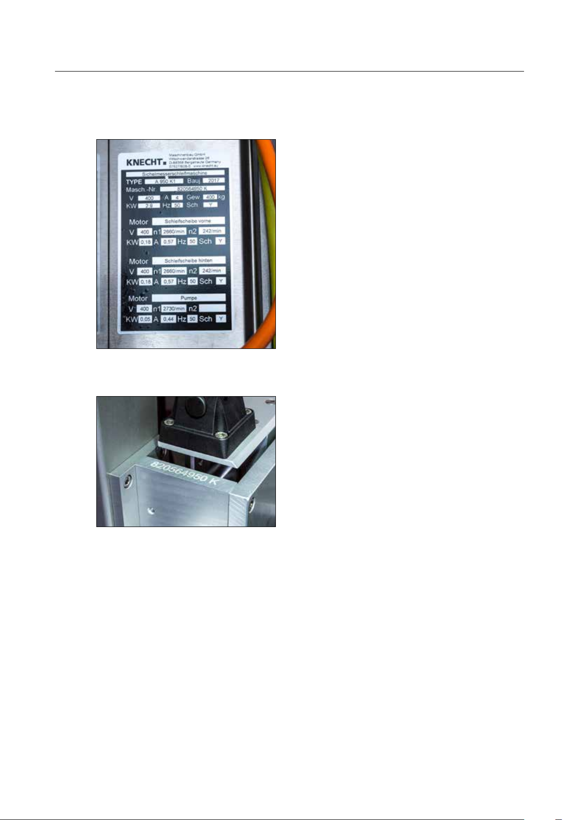
1.4 Rating plate and serial number
The rating plate is located on the right side of the
machine behind the switch cabinet.
Figure 1-1 Rating plate
Figure 1-2 Serial number
The serial number is located on the rating plate
and on the front left of the machine.
9
Page 9
1. Important notes
1.5 Figure and item numbers in the operating instructions
If the text refers to a machine component shown in a figure, a figure or item number is added in
brackets after the machine component.
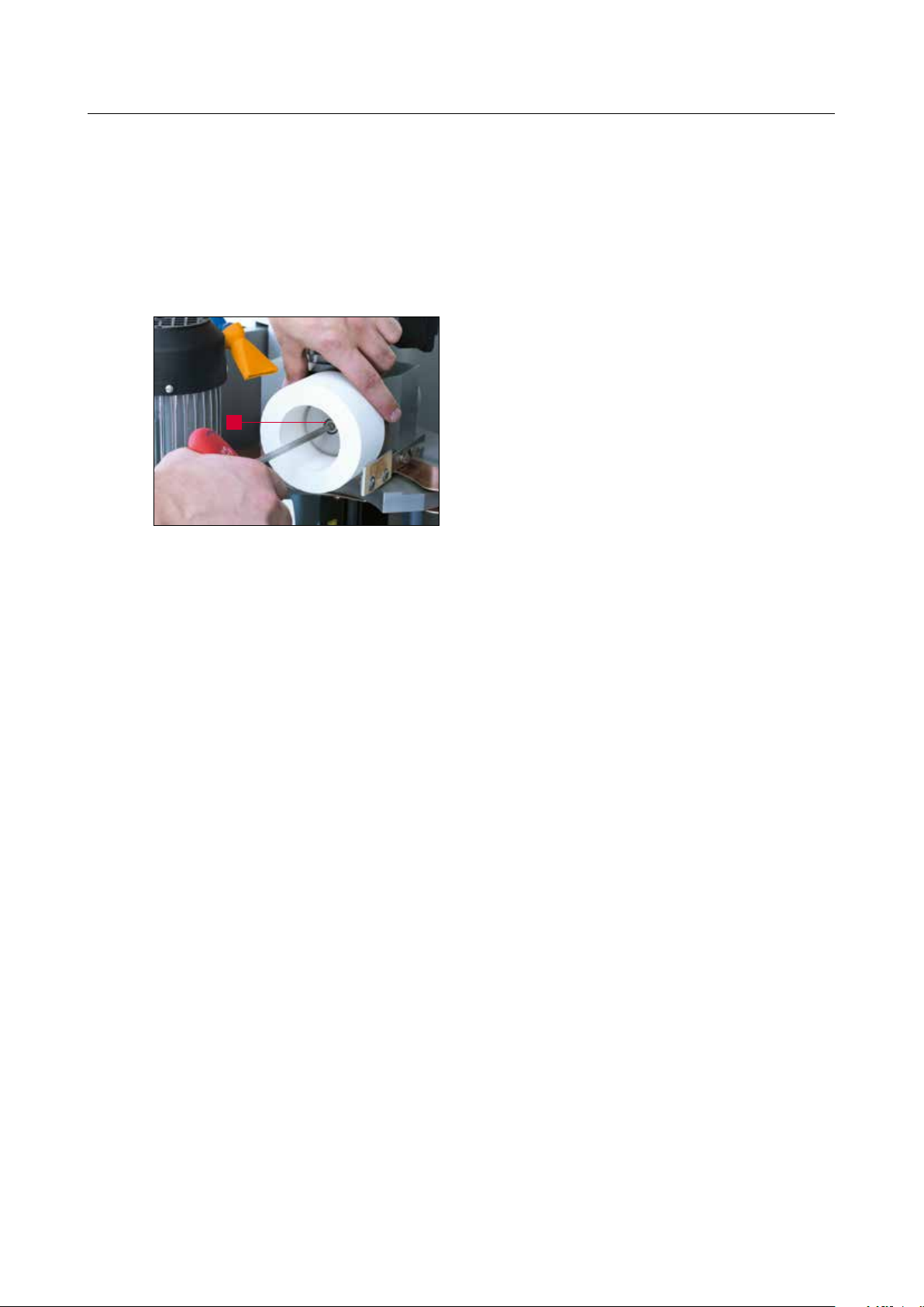
Example: (7-25/1) denotes figure number 7-25, item 1.
Use SW6 Allen wrench to loosen and remove the screw
at the center of the grinding wheel (7-25/1) by turning it
counter-clockwise.
Remove the front or rear grinding wheel and also the con-
1
nection flange (7-26/1) if necessary and mount the new
grinding wheel in the reverse order.
Figure 7-25 Change grinding wheels
10
Page 10

2. Safety
2.1 Basic safety instructions
2.1.1 Observe notes in the operating instructions
The basic prerequisite for safe handling and trouble-free operation of this grinding machine is
familiarity with the basic safety instructions and regulations.
• This user manual contains important notes on how to operate the grinding machine safely.
• This user manual, in particularly the safety notes, is to be read by all those who work at the
grinding machine.
• In addition, the rules and regulations regarding accident prevention at the place of use are to be
observed.
2.1.2 Obligation on the part of the operator
The operator is obliged to allow only those persons to work on the grinding machine, who
• are familiar with the occupational safety and accident prevention regulations and have been
received instruction in handling the grinding machine
• have read and understood the operating instructions, in particular the section entitled “Safety”
and the warning notes, and have provided signed confirmation of this.
Checks are also carried out at regular intervals to ensure that the personnel are fulfilling their
obligation to observe safety at work.
2.1.3 Obligation on the part of the personnel
All personnel working on the grinding machine undertake to
• observe basic occupational safety and accident prevention regulations
• read the operating instructions, particularly the section entitled “Safety” and the warning notes,
and provide signed confirmation of this
2.1.4 Hazards involved in handling the grinding machine
The grinding machine has been built to the latest technological standards and the established
rules of technical safety. In spite of this, its use poses inherent risks which could result in bodily
harm or even death of the user or third parties, or impairment of the grinding machine or other
property. The grinding machine may only be used:
• for its intended purpose
• in faultless condition with regard to safety-related aspects
Faults that might impair safety must be eliminated immediately.
11
Page 11

2. Safety
2.1.5 Malfunction
If any safety-relevant malfunction occurs in the grinding machine or if the processing response
indicates that such malfunction may have occurred, the grinding machine must be stopped immediately until such time as the malfunction has been detected and eliminated.
Malfunctions may only be eliminated by authorized specialists.
2.2 Intended use
The grinding machine is only designed for grinding slicer knives. Before starting work on a slicer
knife, a check must first be carried out as to whether the slicer knife fits onto the cam disc Only
then may the slicer knife be clamped onto the cam disc.
Any other use is considered improper use. KNECHT Maschinenbau GmbH assumes no liability for
damages resulting from improper use. The user alone bears the risk in such cases.
Use as intended includes the observance of all the instructions in the operating instructions.
The grinding machine is being used improperly if, for example:
• the slicer knife is removed without the cam disc
• attachments are not properly mounted
2.3 Warranty and liability
Warranty and liability claims in case of personal injuries or property damage are excluded if such
damage is attributable to one or more of the following causes:
• improper use of the grinding machine
• improper transportation,commissioning, operation and maintenance of the grinding machine
• operating the grinding machine with defective safety devices, or using improperly attached or
malfunctioning safety and protective equipment
• failure to observe the instructions with regard to transportation, commissioning, operation,
maintenance and repair of the grinding machine
12
• unauthorized structural alterations to the grinding machine
• unauthorized modification of such aspects as drive conditions (power and speed)
• insufficient monitoring of machine parts that are exposed to wear
• use of unapproved replacement and wear parts
Page 12

2. Safety
Use only original replacement and wear parts. If parts are purchased from external suppliers, there
is no guarantee that they are designed and manufactured to withstand the required level of stress
and provide the required level of safety.
2.4 Safety regulations
2.4.1 Organizational measures
All available safety devices must be checked regularly.
Observe prescribed intervals for recurring maintenance work or as specified in the operating
instructions.
2.4.2 Protective equipment
Before commissioning the grinding machine, care must be taken to ensure that all protective
equipment is properly mounted and functional.
Protective equipment may be removed only after the machine has stopped and has been secured
against accidental restarting of the grinding machine.
If sub-components are supplied, the protective equipment must be correctly attached by the
operator according to the instructions.
2.4.3 Informal safety measures
The operating instructions must be permanently available at the place of use of the grinding
machine. In addition to the operating instructions, the generally applicable as well as the locally
relevant accident prevention regulations must also be made available and observed.
All safety alert symbols and danger warnings on the grinding machine must be complete and
clearly legible.
2.4.4 Selection and qualification of personnel
Only trained and instructed personnel may work on the grinding machine. The minimum legal
age for employment must be observed.
The responsibilities of the personnel must be clearly assigned, i.e. commissioning, operation,
maintenance and repair, etc.
Personnel still undergoing training or instruction may only work on the grinding machine under
the permanent supervision of an experienced person!
13
Page 13

2. Safety
2.4.5 Machine control system
Do not make any changes to the software program under any circumstances. Parameters that the
operator can set himself are excluded from this prohibition (e.g. setting the number of cycles).
Only trained and instructed personnel are allowed to activate the control unit.
2.4.6 Safety measures in normal operation
Refrain from any method of working which may pose a risk to safety. Only operate the grinding
machine if all the safety devices are installed and fully functional.
Check the grinding machine for external signs of damage and correct operation of the safety
devices at least once every shift.
Report any changes (including operating behavior) immediately to the department / person
in charge. Where required, shut down the grinding machine immediately and secure against
restarting.
Before switching on the grinding machine, ensure that no one is exposed to any risk from the
start-up of the machine.
If there are any functional faults, stop the machine immediately and secure against restarting.
Have the faults eliminated immediately.
2.4.7 Hazards due to electrical power sources
The switch cabinet must always remain secured against access. Only authorized personnel must
be allowed to access it.
Work on electrical units or operating materials may only be performed by a qualified electrician in
accordance with electrical rules.
Defects, such as damaged cables, cable connections, etc. must immediately be rectified by an
authorized electrician.
Cables marked in yellow are electrically live even when the main switch
is in the off position.
CAUTION
2.4.8 Particular hazard zones
In the area of the grinding wheels, there is a danger of pinching and being drawn in (e.g.
clothing, fingers and hair). Suitable personal protective equipment must be worn.
14
Page 14

2. Safety
2.4.9 Servicing (maintenance, repair) and fault elimination
Maintenance work is to be carried out on schedule by trained personnel. Inform operating
personnel before starting repair work. A responsible supervisor must be appointed.
For all service work, the grinding machine is to be disconnected from the power supply and
secured against accidental restarting. Pull out the mains plug. Cordon off the servicing area as
far as possible.
After completion of the maintenance work and fault rectification, install all the safety devices and
check whether they are fully functional.
2.4.10 Structural modifications to the grinding machine
Modifications, retrofitting or rebuilds of the grinding machine are not allowed without the permission of the manufacturer. This also applies to the installation and adjustment of safety devices.
No alterations may be carried out without the prior written approval of KNECHT Maschinenbau
GmbH.
Immediately replace machine parts which are not in perfect condition.
Only use original replacement and wear parts. If parts are purchased from external suppliers, there
is no guarantee that they are designed and manufactured to withstand the required level of stress
and provide the required level of safety.
2.4.11 Cleaning the machine
Cleaning agents and materials used must be handled properly and disposed of in an environment-friendly manner.
Ensure that wear and replacement parts are disposed of in a safe and environmentally friendly
way.
2.4.12 Oils and greases
When handling lubricants / oils and greases, follow the safety regulations for the product. Observe
special instructions for the foodstuffs sector.
2.4.13 Relocation of the grinding machine
Even when moving the machine a short distance from its site, disconnect it from all external
power supply sources. Before restarting the machine, connect it properly to the current supply.
When loading or unloading, only use hoisting and load lifting equipment with sufficient
load-bearing capacity. Appoint a qualified banksman (signaler) for the lifting process.
No persons other than those entrusted with this work may be present in the loading and
installation area.
15
Page 15

2. Safety
Only lift the grinding machine correctly with hoisting gear in accordance with the operating
instructions (attachment points for hoisting equipment, etc.). Only use suitable transport vehicles
with sufficient load-bearing capacity. Attach the load securely. Use appropriate attachment points
(Chapter 4.1). When putting in operation again, proceed only as instructed in the operating
instructions.
16
Page 16

3. Description
3.1 Intended use
The grinding machine for sickle-shaped and circular knives A 950 II grinds slicer knives ( sickleshaped or circular) up to a maximum size of 900 mm. It is not suitable for grinding other types of
knife such as hand knives.
3.2 Technical specifications
Height ������������������������������������������������������������������� 1832 mm
Width �������������������������������������������������������������������� 1709 mm
Depth ���������������������������������������������������������������������� 997 mm
Required space (BxD) ������������������������������������������������� 2500 x 2000 mm
Weight ���������������������������������������������������������������������� 400 kg
Power supply ��������������������������������������������������������������� 3x 400 V
Mains frequency ��������������������������������������������������������������� 50 Hz
Output ���������������������������������������������������������������������� 0.5 kW
Power consumption ����������������������������������������������������������� 1.9 kW
Energy consumption ������������������������������������������������������������� 4 A
Back-up fuse ������������������������������������������������������������������� 16 A
Control voltage ������������������������������������������������������������ + 24 V DC
Compressed air ������������������������������������������������������� 6 bar (50 l / min)
Measured A-evaluated emission sound pressure level ����������������������������� 72 dB (A)
at workstation LpA*
Speed of grinding wheels, front / rear ������������������������������������������� 255 rpm
Grinding wheel A ������������������������������������������������������ d.100xd.40x60
*) Dual number noise emission value information according to EN ISO 4871.
Emission sound pressure level according to EN ISO 11201. Uncertainty KpA in decibels: 3
A slicer knife was ground (type known to KNECHT Maschinenbau GmbH).
17
Page 17
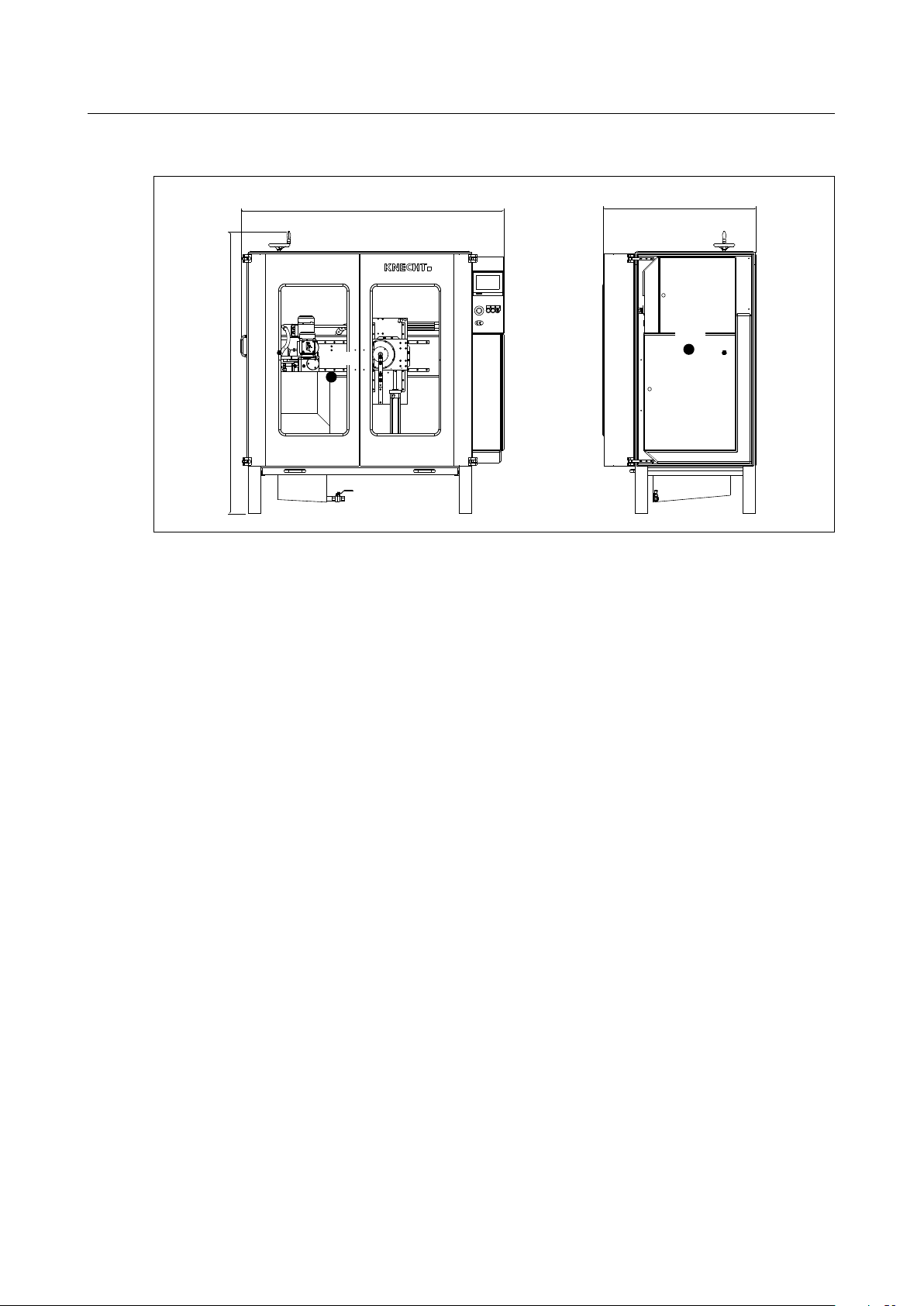
1709 mm
1832 mm
3. Description
1709 mm
GoC
1832 mm
Figure 3-1 Dimensions in mm
3.3 Functional description
997 mm
GoC
The grinding machine can be used to automatically sharpen slicer knives (sickle-shaped or circular
knives) with a size of maximum 900 mm.
The slicer knife is clamped onto a cam disc and sharpened along the knife edge by the grinding
wheel precisely according to its shape.
In case of emergency, the grinding machine can immediately be stopped by pressing the
“Emergency Stop” button
18
Page 18
3. Description
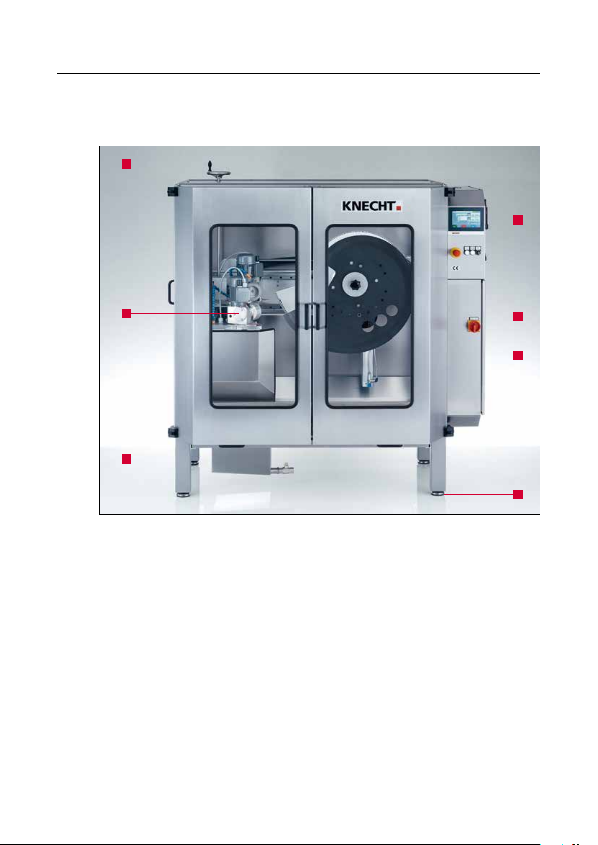
3.4 Description of modules
1
4
2
3
Figure 3-2 General view of grinding machine
1 Hand wheel for grinding depth
2 Grinding unit
3 Water tray
4 Control unit with control panel
5 Cam disc SP 116 (with knive)
6 Water regulator
7 Machine feet
5
6
7
19
Page 19
3. Description
3
3
1
2
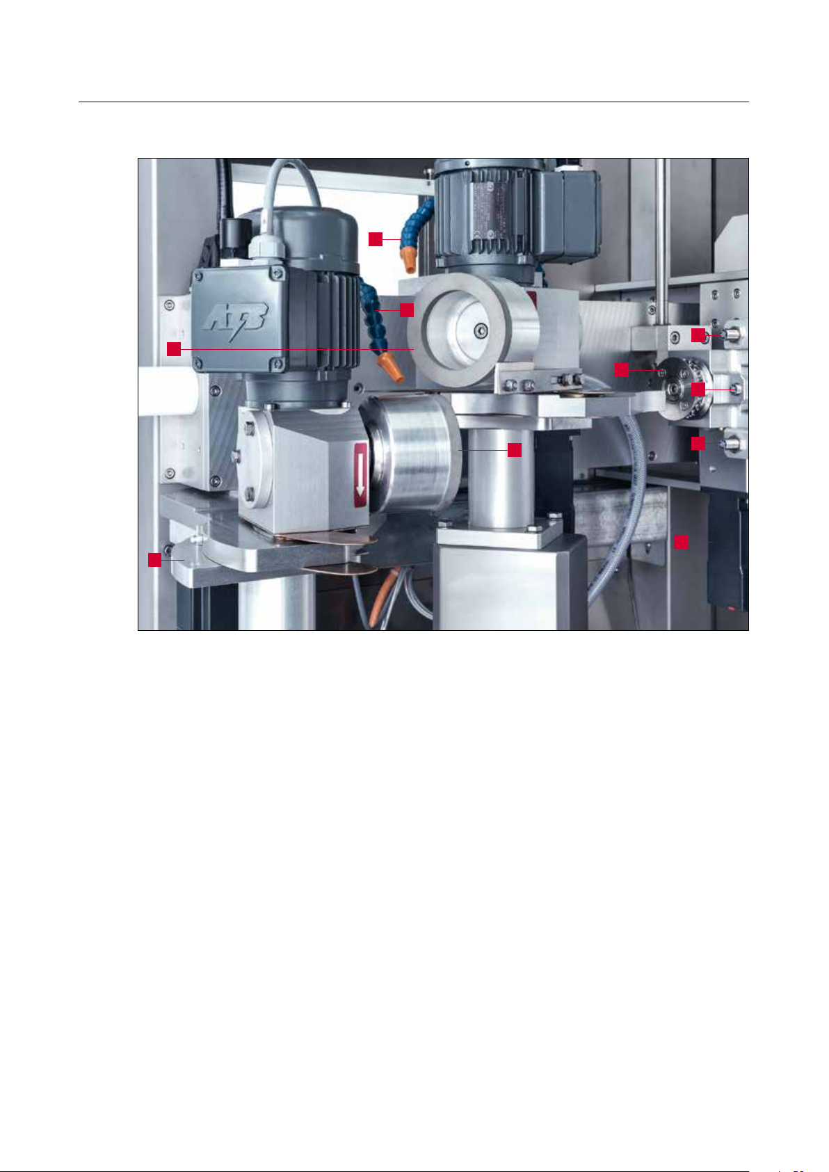
Figure 3-3 Grinding unit
1 Grinding wheel (rear)
2 Angle adjustment scale
3 Coolant hose
4 Inductive switch
5 Drive pinion of cam disc
6 Grinding wheel (front)
7 Cam disc drive (servo motor)
4
5
4
6
4
7
20
Page 20
3. Description
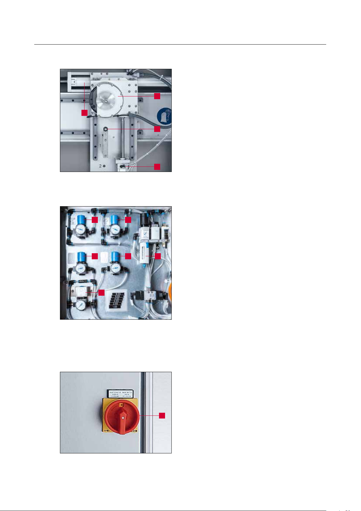
4
Figure 3-4 Cam disc bracket
1
3
2
4 5
1 Cylinder knife assembly up / down
2 Z coupling
3 Cam disc bracket
3
2
1
4 Cylinder for pressing on cam disc
1 Pressure on front grinding wheel
2 Pressure on rear grinding wheel
3 Front grinding wheel clamp
4 Rear grinding wheel clamp
5 Maintenance unit
6 Cam disc pressure
6
Figure 3-5 Pneumatic cabinet
3.4.1 Switching the grinding machine on / off
1 Main switch
Turning the main switch from “0” to “I” switches
on the grinding machine.
1
Figure 3-6 Main switch
Turning the main switch from “I” to “0” switches
off the grinding machine.
21
Page 21
3. Description
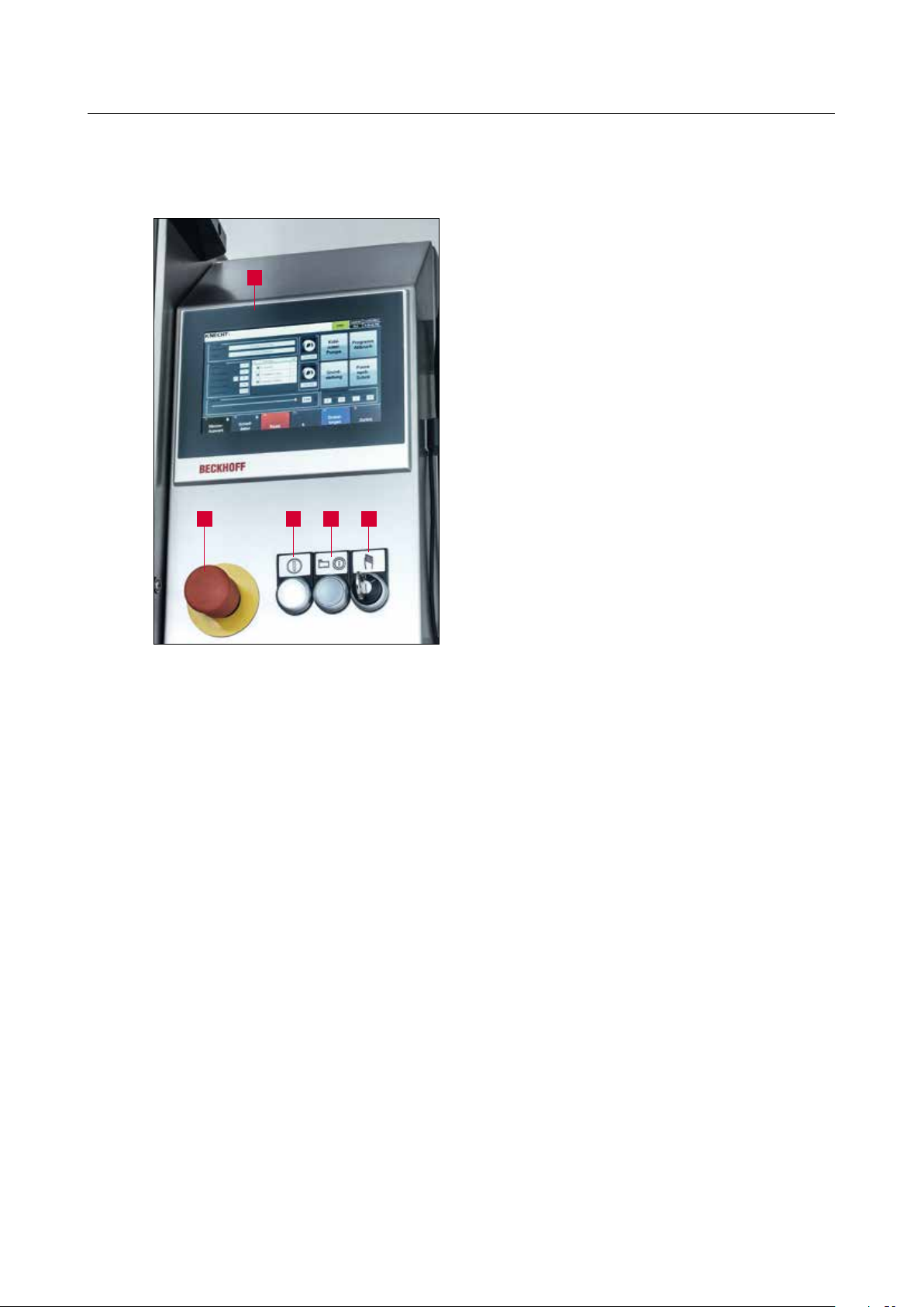
3.4.2 Control panel
1
32
4 5
1 Touch panel
2 “Emergency Stop” button
3 “Control ON” button
4 “Start / Stop” button
5 “Setting Mode” key switch: Position “1”
for setting mode, Position “0” for automatic mode
Figure 3-7 Control panel
22
Page 22

3. Description
3.4.3 Layout of user interface (main screen)
1
3 5
4
11
12 13 14 15 16
Figure 3-8 Main screen
2
7
6
9
8
10
1 Error messages
2 Status display
3 Product data (loaded grinding program)
4 Current processing step settings (stored in grinding program)
5 Tool front (front grinding wheel)
6 Rool rear (rear grinding wheel)
7 Coolant pump (switch coolant pump on / off)
8 Program abort (resets program after stop)
9 Home position (move grinding wheel to change position)
10 Pause after Step (program stops after current step)
11 Override (adapt speed to grinding disc)
12 “F1 Knife Selection”: select the desired grinding program, see Chapter 8.2
13 “F2 Grinding Data”: see Chapter 8.3
14 “F3 Reset”: delete current error
15 “F5 Settings”: see Chapter 8.4
16 “F6 Back”: return to previous screen
NOTICE
The assignment of the touch panel buttons
varies according to the current display screen.
The respective assignment is indicated in text
form.
23
Page 23

4. Transport
For transporting the machine, the locally applicable safety and accident
prevention regulations must be observed.
Only transport the machine in the upright position (with the machine
CAUTION
4.1 Transport aids
For transporting and for setting up the grinding machine, only use adequately dimensioned
means of transport, e.g. truck, forklift or hydraulic lift truck. Remove the water bowl before
transporting.
When using a forklift or a lift truck, move the fork under the grinding machine.
Bear in mind the center of gravity of the machine. The center of gravity (CoG) is shown in figure
3-1.
feet facing downwards).
4.2 Transport damage
If damage is detected on unloading after acceptance of the delivery, inform KNECHT Maschinenbau GmbH and the freight forwarder immediately. If required, consult an independent expert
immediately.
Remove the packaging and shipping straps. Remove the shipping straps on the grinding machine.
Dispose of the packaging in an environment-friendly way.
4.3 Transport to another installation site
For transport to another installation site, ensure that space requirements are fulfilled (see Chapter
3.2).
A reliable electrical connection must be provided at the new installation site.
The grinding machine must be stable and firmly placed.
Installations on the electrical system may only be performed by an
authorized specialist or our customer service staff. Observe the locally
applicable safety and accident prevention regulations.
24
CAUTION
Page 24

5. Installation
5.1 Selection of qualified personnel
We recommend having the grinding machine installed by trained KNECHT
personnel.
We assume no liability for damage caused by improper installation.
CAUTION
5.2 Installation site
When determining the installation site, bear in mind the space required for installation, maintenance and repair work on the grinding machine (see Chapter 3.2). The machine may only be
stored or operated in dry rooms.
5.3 Supply connections
The grinding machine is delivered ready for connection with the appropriate connection cable.
Have a qualified electrician on site install the current supply.
Have a qualified technician on site install the compressed air supply.
Connect compressed air only when the doors are closed.
Never cut off the compressed air while the knives are clamped.
This can result in serious injuries.
CAUTION
5.4 Settings
The various components and the electrical system are adjusted by KNECHT Maschinenbau GmbH
prior to delivery.
ATTENTION
Unauthorized changes to set values are not
permitted and may damage the grinding
machine
25
Page 25

5. Installation
5.5 Using the grinding machine for the first time
Place the grinding machine at the installation site on a level base.
Level out any floor unevenness by adjusting the machine feet (see Chapter 3.4, Figure 3-2/7)
using a flat wrench (SW17). Check the machine for correct horizontal and vertical positioning by
laying an appropriate machine water level on the respective guide rails.
Dismantle all the handling devices on the machine. Ensure that all the axes can be moved freely.
Completely install and check the safety devices before commissioning.
Be sure to have all the safety devices checked by trained personnel
before commissioning.
CAUTION
26
Page 26

6. Commissioning
All work on the machine may only be performed by trained personnel.
The locally applicable safety and accident prevention regulations must be
observed.
CAUTION
Connect compressed air only when the doors are closed.
Never cut off the compressed air while the knives are clamped.
This can result in serious injury.
Fill the water basin (3-2/3) to 3 cm below the rim with water.
Open the safety doors.
1
2
1
3
Figure 6-1 Set coolant hoses
ATTENTION
Connect the power plug (CEE plug) to the power socket provided on site (3x 400 V, 32 A).
Set the coolant hoses (6-1/1) as illustrated in the
figure. The gap from the rear grinding wheel (61/2) and the front grinding wheel (6-1/3) should
be approx. 5 cm. The coolant hoses must not
come into contact with the grinding wheels.
Observe the minimum gap between the
coolant hoses and the grinding wheels, as
the grinding wheel moves forward when
grinding.
Plug in the compressed air hose at the compressed
air port (6-2/1).
1
Figure 6-2 Compressed air connection
Close the safety doors.
27
Page 27

6. Commissioning
1 2
Figure 6-3 Control panel
ATTENTION
Set the main switch (3-6/1) to “I”. Wait for the
controls to initialize.
Switch on the control unit with the “Control ON”
button (6-3/1) when the “Control ON” button
(6-3/1) starts flashing.
Under no circumstances may the grinding
program be activated using the “Start / Stop”
button (6-3/2).
1
Figure 6-4 Check direction of rotation
ATTENTION
Check the direction of rotation of the coolant
pump.
The direction arrow (6-4/1) indicates the direction
of rotation of the coolant pump.
If required, interchange the phases in the power
plug
Make sure the machine is correctly connected
to the power supply.
If the connection to the voltage supply is
incorrect, the grinding belts and cam disc can
rotate in opposite direction of the prescribed
direction. Incorrect direction of rotation can
result in serious injuries.
28
Page 28

7. Operation
All work on the machine may only be performed by trained personnel.
The locally applicable safety and accident prevention regulations must be
observed.
CAUTION
Never mount the knife without blade guard. This can result in serious
injury.
7.1 Switch on the grinding machine
Set the main switch (3-6/1) to “I”. Wait for the controls to initialize. The main screen (3-8) appears
and the “Control ON” button (3-7/3) flashes.
Press “Control ON” button (3-7/3), then turn key switch (3-7/5) to the “0” position (automatic
mode).
7.2 Grind knives
7.2.1 Load grinding program
1
Figure 7-1 Main screen
Press the touch panel button “F1 Knife Selection”
(7-1/1) on the main screen. The dialog box for
menu item “Open” appears. The grinding programs are located in the “Product Data” folder.
Then select the desired grinding program by
double clicking on the respective file. (grinding programs have the ending “.dat” in the file
name).
The grinding program is now loaded and the
“Open” dialog closes.
Figure 7-2 Select grinding program
29
Page 29

7. Operation
ATTENTION
Use the grinding program that matches the
knife. An incorrect grinding program can
damage the machine and knife.
1
3
2
4
Figure 7-3 Main screen
NOTICE
7.2.2 Mount cam disc SP 116
The selected grinding program appears on the
main screen in the “Filename” line (7-3/1).
Check the abrasives used (7-3/3) and (7-2/4) and
change as necessary.
The images and data must match the abrasives
used.
The name of the grinding wheel matching
the grinding program appears on the main
screen under “Holder” (7-3/2). This name is
engraved on the cam disc.
The appropriate abrasive must be used for
each knife and grinding program.
Figure 7-4 Mount Z coupling
Open the safety doors.
Mount the Z coupling on cam disc SP 116 as
described and tighten using combination wrench
SW19. Here, care should be taken to note the
relevant marking on the Z coupling and the base
plate.
30
Page 30

7. Operation
1 2
Figure 7-5 Mount cam disc SP 116
2 1
Insert cam disc SP 116 (7-5/1) in the bracket
(3-4/3) and tighten with wrench SW19.
Hand tighten the cam disc in such a way that the
boreholes (7-5/2) are oriented in the direction of
the grinding wheels.
The spigot (7-6/1) and centering pin (7-6/2) must
engage appropriately in the cam disc.
Figure 7-6 Spigot and centering pin
ATTENTION
1
Figure 7-7 Move cam disc into change position
Incorrect positioning of cam disc SP 116 can
damage the limit switches and the drive
pinion
Close the safety doors.
Press “Home position” (7-7/1) on the touch panel
in the main menu to move the cam disc into the
change position.
The cam disc moves to a position suitable for
placing of knives.
31
Page 31

7. Operation
ATTENTION
Depending upon the size and dimension of
the knife, the knife can be unwieldy with a
blade guard. Ergonomics.
Do not step inside the machine room in order
to insert the knife.
32
Page 32

7. Operation
7.2.3 Grind the slicer knife without suspension attachment
3
Figure 7-8 Place knife
Never place the knife without blade guard.
This can result in serious injuries.
2
4
1
Open the safety doors.
Place the knife (7-8/1) with blade guard (7-8/2)
on the spigot (7-8/3) and align with the relevant
centering device (7-8/4).
The contour of the cam disc corresponds to the
contour of the knife.
CAUTION
1
3
ATTENTION
Only use knives suitable for the cam disc
(compare label on disc and knife).
Using an incorrect cam disc can damage the
knife and machine
Secure the knife and blade guard from falling
(7-9/3) with one hand and attach the clamping
flange (7-9/1); mount the star handle (7-9/2) with
the other hand.
2
Tighten the star handle (7-9/2). Finally, remove the
blade guard (7-9/3).
Close the safety doors.
Figure 7-9 Clamp knife
33
Page 33

7. Operation
Sharp knife edge, can result in serious injuries.
CAUTION
1 2
Turn the “Setup Mode” key switch (7-10/2) to
“0” and press the “Start / Stop” button (7-10/1).
Open the coolant tap.
The machine starts the grinding process.
When the knife is in working position, press the
“Start / Stop” button (7-10/1) again to stop the
machine.
Figure 7-10 Control panel
NOTICE
If you briefly press the “Start / Stop” button,
the program is interrupted and the button
flashes. The grinding program continues
when the button is pressed again.
Pressing the “Start / Stop” button for 3 seconds aborts the program. The button no
longer flashes. Pressing the button again
starts the program flow once more from the
beginning.
34
Page 34

7. Operation
7.2.4 Grinding the slicer knife with suspension attachment
Open the safety doors.
3
2
Figure 7-11 Suspension attachment
1
2
Place the knife (7-11/2) including blade guard
1
(7-11/3) on the respective suspension attachment
(7-11/1). Place the knife (7-11/2) with guard
(7-11/3) on the spigot (7-12/1).
Align using the centering device (7-12/2).
Figure 7-12 Centering device
3
1
2
Figure 7-13 Suspension attachment
ATTENTION
The contour of the cam disc corresponds to the
contour of the knife.
Secure the knife and blade guard from falling
(7-13/3) with one hand and attach the clamping
flange (7-13/1); mount the star handle (7-13/2)
with the other hand. Tighten the star handle (713/2). Finally, remove the blade guard (7-13/3).
Only use a knife that is suitable for the cam
disc (compare label on disc and knife).
Using an incorrect cam disc can damage the
knife and machine.
35
Page 35

7. Operation
1 2
Figure 7-14 Control panel
Close the safety doors.
Turn the “Setup Mode” key switch (7-14/2) to
“0” and press the “Start / Stop” button (7-14/1).
Open the coolant tap.
The machine starts the grinding process.
When the knife is in working position, press the
“Start / Stop” button (7-14/1) again to stop the
machine.
NOTICE
If you briefly press the “Start / Stop” button,
the program is interrupted and the button
flashes. The grinding program continues
when the button is pressed again.
Pressing the “Start / Stop” button for 3 seconds aborts the program. The button no
longer flashes. Pressing the button again
starts the program flow once more from the
beginning.
36
Page 36

7. Operation
7.2.5 Grind circular knives
Open the safety doors.
2
1
3
Figure 7-15 Place circular knife
1
2
3
Place the knife (concealed in a blade guard (715/1)) with guard (7-15/2) on the spigot (7-15/3).
The contour of the cam disc corresponds to the
contour of the knife.
Secure the knife and blade guard from falling
(7-16/1) with one hand and attach the clamping
flange (7-16/2); mount the star handle (7-16/3)
with the other hand.
Tighten the star handle (7-16/3). Finally, remove
the blade guard (7-16/1).
Close the safety doors.
Figure 7-16 Circular knife
ATTENTION
Only use a knife that is suitable for the cam
disc (compare label on disc and knife).
Using an incorrect cam disc can damage the
knife and machine.
37
Page 37

7. Operation
1 2
Figure 7-17 Control panel
Turn the “Setup Mode” key switch (7-17/2) to
“0” and press the “Start / Stop” button (7-17/1).
Open the coolant tap.
The machine starts the grinding process.
When the knife is in working position, press the
“Start / Stop” button (7-17/1) again to stop the
machine.
NOTICE
If you briefly press the “Start / Stop” button,
the program is interrupted and the button
flashes. The grinding program continues
when the button is pressed again.
Pressing the “Start / Stop” button for 3 seconds aborts the program. The button no
longer flashes. Pressing the button again
starts the program flow once more from the
beginning.
38
Page 38

7. Operation
7.2.6 Set the knife at the center of the disc
Adjust the knife with the hand wheel (7-18/1) in
such a way that the knife edge passes through the
1
Figure 7-18 Set knife
center of the rear grinding wheel.
Check sharpness when the program ends
(“Start / Stop” button no longer flashes).
If the knife is not yet sharp, mark the blade on
both sides with a pencil and grind again.
The marked places indicate whether the knife has
been completely ground or not. If not, adjust the
grinding angle to make it steeper
Figure 7-19 Right
Figure 7-20 Wrong
39
Page 39

7. Operation
There is a risk of clothing and hair getting entangled. There is a risk of
hands being crushed. This can result in serious injury.
To prevent dust formation, always have the coolant tap on while
CAUTION
7.3 Dressing the front / rear grinding wheel
dressing and direct the coolant hose at the grinding wheels.
Never dress with mounted knives.
This can result in serious cut injuries.
If the front grinding wheel is running out of true
or is loaded, it must be dressed.
3
1
2
Figure 7-21 Settings
ATTENTION
2
Close the safety doors.
Change to settings via the main menu “F5 Settings” (3-8/15). Press “Dressing Position” (7-21/1)
on the touch panel to move the grinding wheels
into dressing position.
Turn the “Setup Mode” key switch (3-7/5)
to position “1”.
Open the safety doors.
Switch on the front grinding wheel. To do so,
1
3
press “Grinding wheel front On / Off” (7-21/2) on
the touch panel.
Insert the deburring lever (7-22/1) as far as it will
go into the relevant bushing. Move the dressing
diamond (7-22/2) with the deburring lever evenly
over the grinding wheel, which is switched on.
The dressing diamond is fed by rotating the feed
nut (7-22/3) in clockwise direction.
40
Figure 7-22 Dress front grinding wheel
Page 40

7. Operation
1
Figure 7-23 Dress rear grinding wheel
Switch on the rear grinding wheel (7-23/1) by
pressing “Grinding wheel rear On / Off” (7-21/3)
on the touch panel and carry out dressing as
described above.
41
Page 41

7. Operation
7.4 Changing the front / rear grinding wheels
Close the safety doors.
Change to settings via the main menu “F5 Set-
1
Figure 7-24 Settings
ATTENTION
tings” (3-8/15). Move the grinding wheels into
dressing position by pressing “Dressing Position”
(7-24/1) on the touch panel
Open the safety doors.
Turn the “Setup Mode” key switch (3-7/5)
to position “1”.
1
Figure 7-25 Change grinding wheels
Use SW6 Allen wrench to loosen and remove the
screw at the center of the grinding wheel (7-25/1)
by turning it counter-clockwise.
Remove the front or rear grinding wheel and also
the connection flange (7-26/1) if necessary and
mount the new grinding wheel in the reverse
order.
If the grinding wheel is half-worn, mount the
connection flange (7-26/1) with an M8x40 screw.
1
42
Figure 7-26 Connection flange
NOTICE
Two connection flanges with corresponding
screws are included in the accessories.
Page 42

7. Operation
ATTENTION
Only use original grinding wheels.
Using non-original grinding wheels can
result in damage to the knife and the grinding machine.
43
Page 43

7. Operation
7.5 Adjusting the grinding angle
Figure 7-27 Adjust grinding wheel
The grinding angle of the grinding wheels‚ is
adjusted based on the parameters in the grinding
program (see Chapter 8.3.3)
44
Page 44

8. Control system
8.1 Main screen
1
3 5
4
11
12 13 14 15 16
Figure 8-1 Main screen
2
7
6
9
8
10
1 Error messages
2 Status display
3 Product data (loaded grinding program)
4 Current processing step settings ( stored in grinding program)
5 Tool front (front grinding wheel)
6 Tool rear (rear grinding wheel)
7 Coolant pump (switch coolant pump on/off)
8 Program abort (resets program after stop)
9 Home position (move grinding wheel to change position)
10 Pause after Step (program stops after current step)
11 Override (adapt speed to grinding disc)
12 “F1 Knife Selection”: select the desired grinding program, see Chapter 8.2
13 “F2 Grinding Data”: see Chapter 8.3
14 “F3 Reset”: delete current error
15 “F5 Settings”: see Chapter 8.4
16 “F6 Back”: return to previous screen
NOTICE
The assignment of the touch panel buttons
varies according to the current display screen.
The respective assignment is indicated in text
form.
45
Page 45

8. Control system
8.2 Grinding program
Figure 8-2 Select grinding program
Press “F1 Knife Selection” (8-1/12) on the main
screen.
The “Open” dialog box (8-2) from Windows
appears. The directory C:\Product is automatically
displayed. The grinding programs for the individual knives are filed in this folder. The grinding
programs have the ending “.dat” in the file name.
To load a grinding program, proceed as follows:
Select the desired grinding program. The name of
the selected grinding program appears in the File
Name column. The grinding program is loaded
with one click on the “Open” button.
The “Open” dialog box is closed and the selected
grinding program is displayed in the main menu.
46
Page 46

8. Control system
8.3 Grinding data
The data for the grinding process are entered via the main menu “F2 Grinding Data” (8-1/13).
These data vary according to the knife. The data are saved in a file and can be loaded again from
the file.
ATTENTION
Changing the grinding data can cause malfunction and damage to the machine. Changes may only be made under the supervision
of KNECHT technicians or by persons who
have been trained by KNECHT Maschinenbau.
1 2 3 4 5
Figure 8-3 Grinding data
1 “F1 Load from file”
2 “F2 Save as”
3 “F4 Apply value”
4 “F5 Keyboard”
5 “F6 Back”: return to previous screen
47
Page 47

8. Control system
8.3.1 Data
Figure 8-4 Grinding data “Data”
8.3.2 Abrasives
“Type of knife”: circular / sickle knife
“Rotation direction circular knife”: 0 = left,
1 = right
“Holder”: index as to which holder will be used
for processing the knife
“Processing speed”: processing speed at which
the cam disc rotates during the grinding process
(mm / s)
“Upwards after processing”: true = yes, false = no
(for better assembly or assembly with suspension
protection)
Figure 8-5 Grinding data “Abrasives”
8.3.3 Steps
Figure 8-6 Grinding data “Steps”
“Grinding wheel front”
“Grinding wheel rear”
“Tool”: selection of the abrasives
“Cycles”: number 1, 2, 3
“Angle Tool 1 (front)”: angle adjustment of front
grinding wheel
“Angle Tool 2 (rear)”: angle adjustment of rear
grinding wheel
“Overrun start”: distance limit switch is reached
“Raise front start”: front grinding wheel is raised,
true = yes, false = no
“Raise rear start”: rear grinding wheel is raised,
true = yes, false = no
“Overrun end”: distance limit switch is reached
“Raise front finish”: front grinding wheel is raised
from knife, true = yes, false = no
48
Page 48

8. Control system
“Raise rear finish”: rear grinding wheel is raised
from knife, true = yes, false = no
“Half cycle”: tool only does half cycle
49
Page 49

8. Control system
8.4 Settings
Machine settings other than the basic functions of “Start” or “Stop” are applied using the
“F5 Settings” main menu (8-1/15).
ATTENTION
1 2 3
Changing the settings can damage the
machine.
4 5 6 7 8
Figure 8-7 Settings
1 Dressing (switch grinding wheels on / off or move into dressing position)
2 Coolant pump (switch on / off)
3 Processing time (current knife, last knife and average in mins / secs)
4 “F1 Axes Manual Mode”: axes are moved individually in manual mode
5 “F2 Manual Functions”: allows manual operation of the machine
6 “F3 Machine Data”: for displaying / editing machine data that has been set ex-factory
7 “F4 Message Texts”: display all error messages sequentially (number of messages,
frequency, start)
8 “F6 Back”: return to previous screen
50
Page 50

8. Control system
8.5 Axes in manual mode
Access the sub-menu “F1 Axes Manual Mode” (8-7/4) via the main menu “F5 Settings” (8-1/15).
The “Axes Manual Mode” (8-8) display screen shows the status of the CNC driven machine axes.
The axes can also be controlled manually. The individual axis positions are displayed at the top left
of the sub-menu “Axes Manual Mode”.
5
6
7
1
Figure 8-8 Settings “Axes Manual Mode”
1 “–”: move the selected axes in “–” direction (backwards)
2 “~”: activate rapid traverse in the respective direction in combination with “–” or “+”
3 “+”: move the selected axes in “+” direction (forwards)
4 “F6 Back”: return to previous screen
2 3 4
51
Page 51

8. Control system
The angle movement of the front grinding wheel
is designated “angle front” (8-8/5), that of the
rear grinding wheel is “angle back” (8-8/6).
In order to move the axes manually, select the
desired axis on the touch panel. The selected axis
is highlighted in blue.
The axes can be moved by means of “–” (8-8/1),
“+” (8-8/3) and “~” (8-8/2).
Figure 8-9 Angle of grinding wheels
52
Page 52

8. Control system
8.6 Manual functions
The manual functions allow you to operate the machine by hand. They can be accessed via the
main menu “F5 Settings” (8-1/15) followed by “F2 Manual Functions” (8-7/5). Various functions
of the machine can be individually enabled.
ATTENTION
Buttons highlighted in green are enabled.
Buttons highlighted in gray are disabled.
8.6.1 General
When the sub-menu “F2 Manual Functions” (8-7/5) is accessed, the screen initially switches to
the general manual functions (8-10).
NOTICE
Manual functions are not required in normal
operation. During maintenance work (e.g.
when changing grinding wheels), the individual machine components can be moved to
a more easily accessible position using the
manual functions.
1
3 4 5 6 7
Figure 8-10 Manual functions “General”
1 Switch on lamp test
2 Switch coolant pump on / off
3 “F1 General” (current display)
2
53
Page 53

8. Control system
4 “F2 Grinding wheel front”: see Chapter 8.6.2
5 “F3 Grinding wheel rear”: see Chapter 8.6.3
6 “F4 Knife assembly”: see Chapter 8.6.4
7 “F6 Back”: return to previous screen
8.6.2 Grinding wheel front
1
2
3
4
1 Switch on / off front grinding wheel drive
2 Move grinding wheel forwards / backwards
3 Clamp / release grinding angle adjustment
4 Switch on / off drivecontrol grinding angle
adjustment
Figure 8-11 Manual functions “Grinding wheel
front”
8.6.3 Grinding wheel rear
1
2
3
4
Figure 8-12 Manual functions “Grinding wheel
rear”
8.6.4 Knife assembly
1
2
3
4
1 Switch on / off rear grinding wheel drive
2 Move grinding wheel forwards / backwards
3 Clamp / release grinding angle adjustment
4 Switch on / off drivecontrol grinding angle
adjustment
1 Move knife assembly up / down
2 Move knife assembly forwards / backwards
3 Open / close brake
4 Switch on / off limits (machine does not
move beyond the limit switches in manual
mode)
54
Figure 8-13 Manual functions “Knife assembly”
Page 54

8. Control system
ATTENTION
Only open the brake when the knife assembly has previously been moved away and
forwards. Otherwise there is a risk of damage
to the machine, since the cam disc can impact
against the side wall in an uncontrolled
manner.
55
Page 55

8. Control system
8.7 Machine data
Access the sub-menu “F3 Machine data” (8-7/6) via the main menu “F5 Settings” (8-1/15). The
“Machine data” display (8-14) shows the basic machine settings. The data are saved in a file and
can be loaded again from the file.
Figure 8-14 Machine data
1 “F1 Load from file”
2 “F2 Save as”
3 “F4 Apply value”
4 “F6 Back”: return to previous screen
8.7.1 General
Figure 8-15 Machine data “General”
“Coolant pump on”: true = always on,
false = only on at program start
“Waiting time after switching on coolant pump”:
(in secs)
56
Page 56

8. Control system
8.7.2 Options
Figure 8-16 Machine data “Options”
8.7.3 Holder
“Grinding wheel front”: true = available,
false = not available
“Grinding wheel rear”: true = available,
false = not available
“Coolant monitoring available”: true = yes,
false = no
“Speed homeposition”: (mm / s)
“Speed process”: (mm / s)
“Waiting time knife assembly forward / backward”: (in secs)
“Waiting time knife assembly up / down”: (in secs)
“Waiting time opening brake” (in secs)
“Dwell time change of direction”: (in secs)
Figure 8-17 Machine data “Holder”
8.7.4 Tools – Grinding wheel front / rear
Figure 8-18 Machine data “Grinding wheel
front / rear”
“Home position”: (in mm)
“Service position”: (in mm)
57
Page 57

8. Control system
8.8 Message texts
Figure 8-19 Message texts
The Message Texts screen (8-19) serves only to
display the status messages of the machine in
detail.
The Message Texts screen provides an overview
of the number of errors that are hindering the
operation of the machine at a particular moment.
Furthermore, the sub-menu provides information
as to which errors have occurred and since when
they have been active.
NOTICE
No settings can be applied in the Message
Texts sub-menu. The errors are also displayed
in the top half of the main screen (8-1/1).
58
Page 58

8. Control system
8.9 Options
Figure 8-20 Main screen
Other options such as language settings can be
accessed via the main menu.
Press “F6 Back” (8-20/1) on the touch panel to
get back to the start screen.
1
Press “F5 Options” (8-21/1) on the touch panel.
A new window (8-22) opens.
Figure 8-21 Start screen
3 421
Figure 8-22 Options
1
1 “F1 Sysinfo”
2 “F2 Settings”
3 “F3 Language”: change language
4 “F6 Back”: return to previous screen
59
Page 59

8. Control system
8.10 Language
Figure 8-23 Main screen
The user interface language can be changed to
the language of the country of use. The parameter
descriptions are always in English.
In the main menu, press “F6 Back” (8-23/1) on
the touch panel to get back to the start screen.
1
Press “F5 Options” (8-24/1) on the touch panel.
A new window (8-25) opens.
Figure 8-24 Start screen
1
Figure 8-25 Options
12
Use “F3 Language” (8-25/1) to open the language
selection (8-26).
The desired language is selected and automatically
activated by pressing the corresponding touch
panel button (8-26/1).
60
1
Figure 8-26 Select language
Then press “F6 Back” (8-26/2) on the touch panel
to return to the start screen.
2
The main screen appears on pressing “F4 Production” (8-24/2).
Page 60

8. Control system
8.11 Setting up an internet connection
The machine has a network connection which
can be used to establish a direct link between the
1
Figure 8-27 Network connection
machine and KNECHT. The connection allows the
display screen content on the grinding machine
to be transmitted. In this way, the manufacturer's
technicians can perform a diagnosis of the machine, change software settings and install or edit
new grinding programs.
“Team Viewer”, the program pre-installed on your
machine, is required in order to set up the internet
connection. An active internet connection must be
available.
NOTICE
Please have the internet link established by
your network administrator.
61
Page 61

9. Care and maintenance
For all work on the grinding machine, the locally applicable safety and
accident prevention regulations as well as instructions in the “Safety”
and “Important Notes” section of the operating instructions must be
observed.
CAUTION
9.1 Coolant
The cooling water has to be replaced every week
and the water tray must be cleaned.
1
Figure 9-1 Water tray
9.2 Lubricate cross table
The water trough must always be filled with water
up to 3 cm below the rim. The water trough can
be pulled out in front for filling and cleaning.
The pump (9-1/1) including the guard can be
2
removed by loosening and removing the star handles (9-1/2).
Place grease gun on the lubrication points and
lubricate the cross table.
We recommend “OEST Multi-Purpose Grease L2”
or a similar commonly available product.
Press one round of grease into the lubrication
point using the grease gun once a month.
62
Figure 9-2 Lubricate cross table
Page 62

9. Care and maintenance
9.3 Clean grinding machine
After grinding and / or dressing work, the grinding machine must be cleaned with a moist rag or a
wet vacuum cleaner. Rub acid-free oil into the grinding machine. Clean the window with window
cleaning agent.
Do not spray-wash the grinding machine
ATTENTION
9.4 Other lubrication points
1
with water. This can damage the machine.
Press one round of grease into the lubrication
points at the marked places with grease gun once
a month. Grease the spindle (9-3/1) once every
month.
Figure 9-3 Adjustment axis
63
Page 63

10. Malfunctions
10.1 Faults
Malfunction Fault Remedy
Knife is not being sharpened The knife edge is not
reached during the grinding operation, i.e. the
grinding angle is too flat
Burr formation on the
knife edge
Number of cycles is set too
low
Grinding wheel is worn Mount connection flange or new
The grinding machine does
not run after pressing the
“Start” button
Control unit cannot be
switched on
Protection hood is open Close the protection hood
“Emergency Stop” button
is activated
Control unit is not
switched on
Motor protection switch
has tripped
Set a steeper grinding angle
Use a less aggressive rear grinding
wheel
Increase the number of cycles
grinding wheel
Release the “Emergency Stop”
button and press the “Control ON”
button
Press the “Control ON” button
Switch on the motor protection
switch
If a fault is not included in the faults table or if the fault is not eliminated, please contact our
service staff (Chapter 12.2).
64
Page 64

11. Disassembly and disposal
11.1 Disassembly
The operating materials must be disposed of correctly.
Secure moving parts against slipping.
The disassembly must be carried out by a qualified specialist company.
11.2 Disposal
At the end of service life, the machine must be disposed of by a qualified specialist company. In
exceptional cases and by agreement with KNECHT Maschinenbau GmbH, the machine can be
returned.
Operating materials (e.g. grinding wheels, coolants etc.) must also be disposed of correctly.
65
Page 65

12. Service, spare parts and accessories
12.1 Postal address
KNECHT Maschinenbau GmbH
Witschwender Straße 26
88368 Bergatreute
Germany
Phone +49 -7527-928-0
Fax +49 -7527-928-32
mail@knecht.eu
www.knecht.eu
12.2 Service
Service management:
See postal address
service@knecht.eu
12.3 Spare parts
If you need spare parts, please use the spare parts list provided with the machine. Please place
your order as shown below.
Please always include the following information: (Example)
Machine type (A 950 II)
Serial no. (050158950)
Designation of module (Slide X module)
Designation of component (Cam disc bearing shaft Z axis)
Item no. (12)
Drawing no. (2000130-12428)
Quantity (1)
Please feel free to contact us if you have any questions.
66
Page 66

12. Service, spare parts and accessories
12.4 Accessories
12.4.1 Abrasives used
Name Dimension Standard Order number
Boron nitride grinding wheel
15 / 10 K300NA-B46-C60
d.100x60x40 EN 171741 412F-73-1510-46
Only use original grinding wheels.
ATTENTION
Using non-original grinding wheels can result
in damage to the knife and the grinding
machine.
If you require grinding wheels or other accessories, please contact our sales staff, dealers, or
KNECHT Maschinenbau GmbH directly.
Thank you for buying our product!
67
Page 67

13. Appendix
13.1 EC Declaration of Conformity
in accordance with the EC Directive 2006 / 42 / EC
• Machinery Directive 2006 / 42 / EC
• Electromagnetic Compatibility Directive 2004 / 108 / EC
We hereby declare that the machine mentioned below fulfills the basic health and safety requirements of the relevant EC Directive by virtue of the machine's construction and design and the
version placed by us on the market.
This declaration becomes void if the machine is modified in any way without our consent.
Designation of the machine: Grinding Machine for Sickle-shaped and Circular Knives
Type designation: A 950 II
Applicable harmonized standards, DIN EN ISO 12100
in particular: DIN EN ISO 13850
DIN EN ISO 13857
DIN EN 13218
DIN EN 60204-1
DIN EN 349
Responsible for documentation: Peter Heine (Dipl. Ing. Mechanical Engineering BA)
Phone +49 -7527-928-40
Manufacturer: KNECHT Maschinenbau GmbH
Witschwender Straße 26
88368 Bergatreute
Germany
Complete technical documentation is available. The operating instructions document for the
machine is available in its original version and in the native language of the user.
68
Bergatreute July, 13 2017 Managing Director
–––––––––––––––––––––––––– –––––––––––––––––––––––––– ––––––––––––––––––––––
Place, date Signed Signatory details
Page 68

KNECHT Maschinenbau GmbH
Witschwender Straße 26
mail@knecht.eu
■ 88368 Bergatreute ■ Germany ■ T + 49
■ www.knecht.eu
-
7527- 928-0 ■ F + 49 -7527- 928-32
 Loading...