

Knape & Vogt 8150 Installation Instructions Manual

8150 Variable-Height Keyboard Slide
KV 8150 Major Dimensions and Mounting Hole Locations
Slide
Size
Side
Travel
A
B
C
D
E
F
G
12* 13 14* 15 16* 17 18* 19 20* 21 22* 23 24* 25 26* 27 28* 29
30*
Specifications
• 7 position, adjustable and reversible mounting bracket.
• Friction latch securely holds keyboard in extended position.
• Metal Ball Bearing Retainer and three precision steel ball bearings per inch of race for
smooth quiet movement and durability.
• Drawer track member disconnects quickly using positive lever release for easier installation.
• Anti-rebounding, Stay-Close feature holds tray in closed position.
• Bright electro-zinc plated with lacquered finish for better corrosion resistance. Black finish available.
PATENTS PENDING
Installation Instructions for:
8150 Variable-Height Keyboard Slide
For Best Results, Read Instructions First!
These instructions show how to install the KV 8150
Keyboard Slide. Please note that improper
installation may void the Knape & Vogt Lifetime
Limited Warranty. To install the slides correctly,
follow these instructions, use only KV hardware,
and make no modifications. If you have questions
or need additional information, please contact the
factory.
Application
• Recommended for keyboards.
• Mounting brackets adjust from 2-11/32" to
3-11/16" in 7/32" increments.
• Maximum keyboard tray width not exceeding 24
inches.
• Cabinet members must be mounted parallel
to each other and perpendicular to the work
surface front.
• Use #8 x 5/8" Pan Head screws to mount
slide to surface and tray. Use #8 x 1/4" thread
cutting screws to secure adjustable brackets
at desired height.
• Consult factory for advice on unusual
applications.
Installation
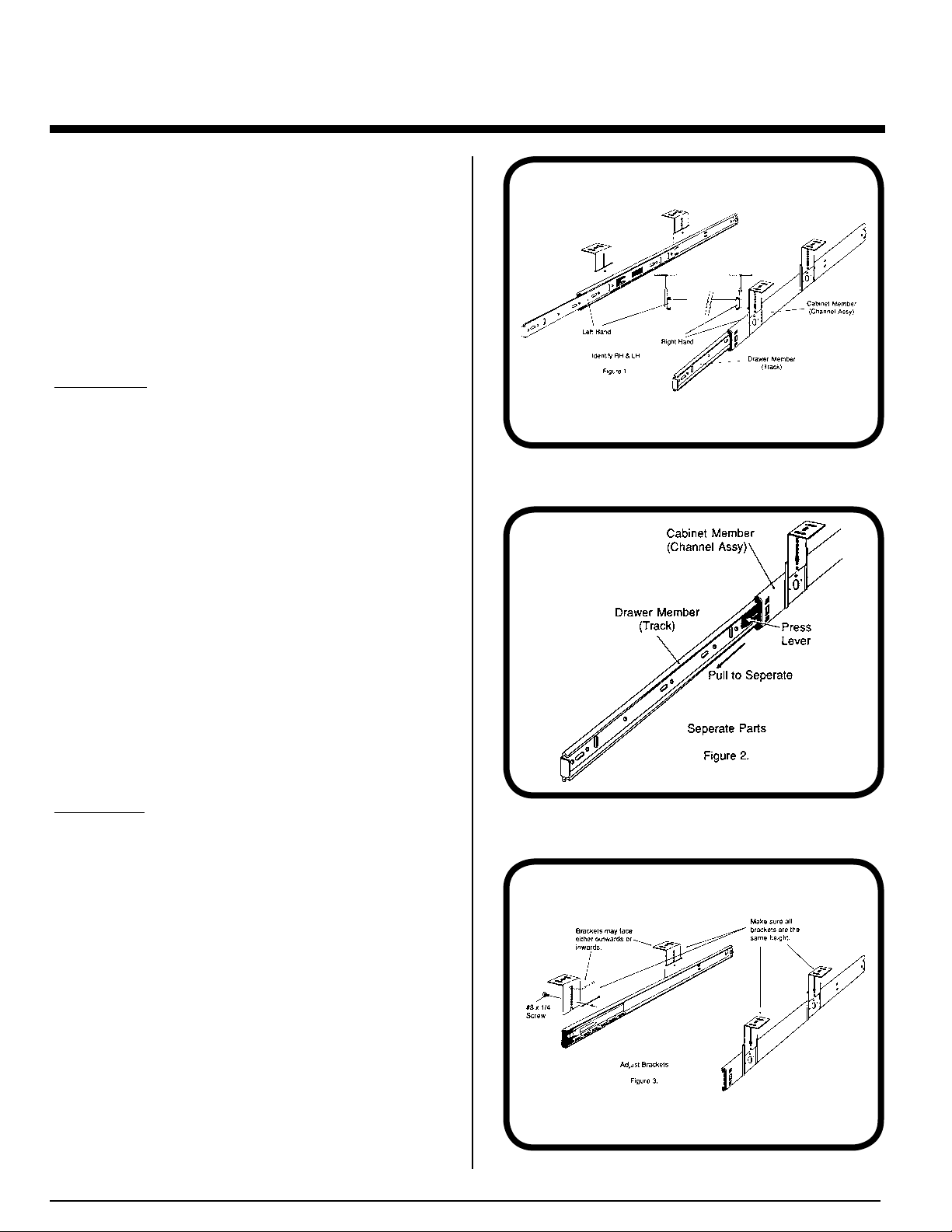
Step 1 Identification.
Unpack the slides and identify the left hand and right
hand slides. The mounting plates are welded to the
outside of the (larger) cabinet members. The
keyboard tray will fit flush against the side of the
(smaller) drawer members. See figure 1. The right
angle mounting brackets are packaged with left and
right hand slides unattached.
Figure 1.
Figure 2.
Figure 3.
 Loading...