


A
B
C
D
E
F
G
H
I
C
J
K
L
N
M
O
P
P
Q
Q
O
O
O
J
J
L
L
N
N
S
O
R
U
P
Q
O
O
Q
P
O
S
Q
P
W
O
M
Q
S
V
Z
Y
X
T
77-9034KP
TOOLS NEEDED:
PARTS LIST:
Description Qty. Part # Description Qty. Part # Description Qty. Part #
NOTE: This kit was not designed
to t vehicles with a body lift.
1. Turn o the ignition and disconnect the negative
battery cable.
NOTE: Disconnecting the negative battery cable
erases pre-programmed electronic memories.
Write down all memory settings before
disconnecting the negative battery cable. Some
radios will require an anti-theft code to be
entered after the battery is reconnected. The
anti-theft code is typically supplied with your
owner’s manual. In the event your vehicles’
anti-theft code cannot be recovered, contact an
authorized dealership to obtain your vehicles
anti-theft code.
TO START:
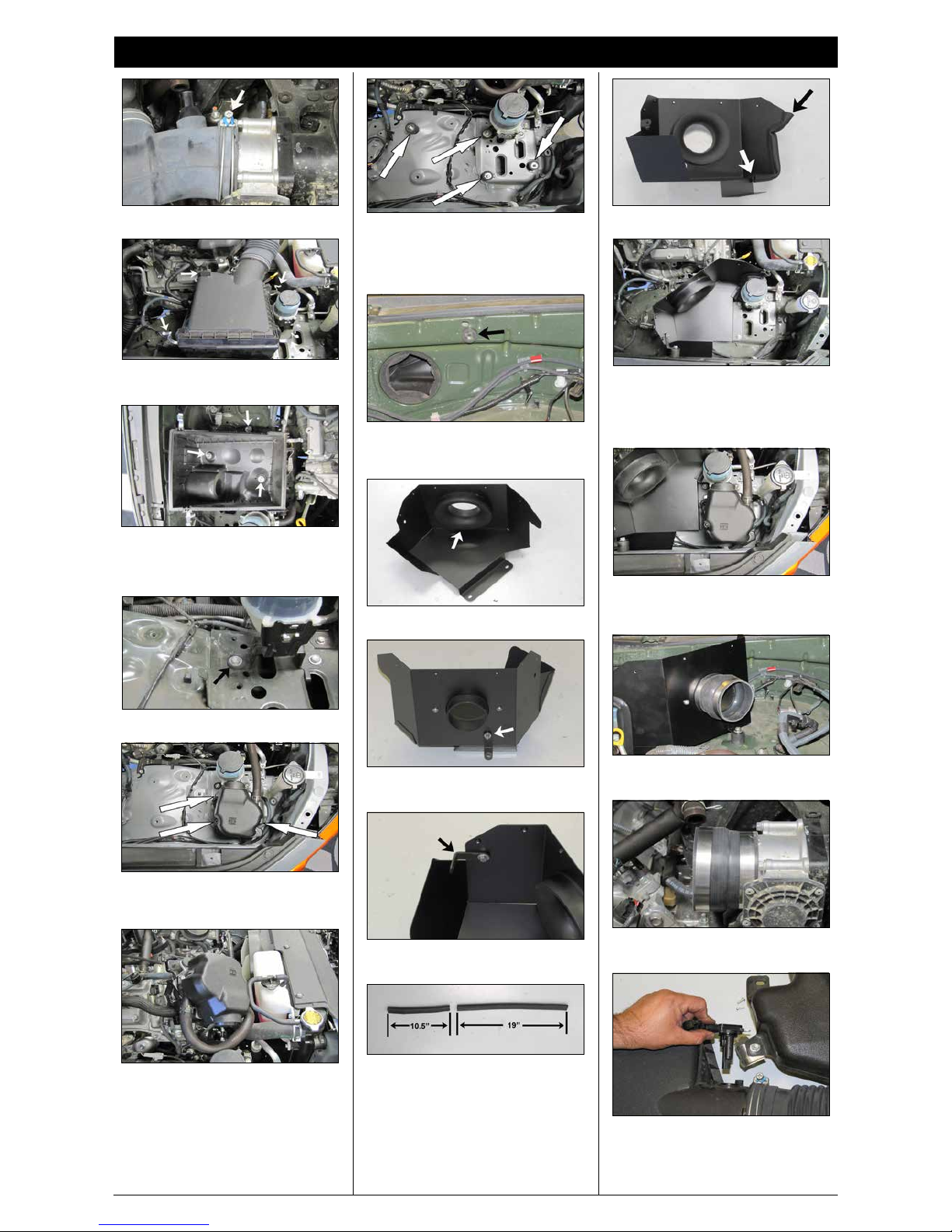
2. Lift up the engine cover to dislodge it from the
mounting grommets and then remove the cover
from the vehicle.
TOYOTA
2010-14 FJ Cruiser
2010-18 4Runner
V6-4.0L
Ratchet
Extension
13mm socket
12mm socket
10mm socket
10mm wrench
Wrench
3mm allen wrench
Pliers
Flat blade screw driver
3. Disconnect the mass air sensor electrical
connection and then unhook the wiring harness
from the air box.
NOTE: The wiring harness attaches in three
locations.
4. Unhook the fuel pressure vent line from the fuel
pressure regulator.
5. Disconnect the crank case vent hose from the
stock intake tube.
6. Remove the bolt which secures the tube
mounting bracket to the engine valve cover.
A HOSE CLAMP #48 1 08601
B HOSE: 3.25”ID TO 3.50 ID 1 084091
C HOSE CLAMP #56 3 08620
D HOSE; 4MM ID X 18” L 1 08153
E VENT; STRT, 3/16 1 080021
F VENT; STRT, 5/8 BARBED 1 08911
G BOLT; M4-0.07 8MM, A/H 2 07733
H INTAKE TUBE 1 27472
I HOSE; 3-1/2”ID X 3”L 1 084057
J STUD; M/M 8MM X 1.25 4 070227
K BRACKET “L” 1 070712
L WASHER; 8MM, FLAT, SS 4 08272
M NUT; 6MM NYLOCK, HEX 2 07512
N NUT; 8MM NYLOCK, SS 4 07502
O WASHER; 1/4”ID X 5/8”OD 13 08275
P BOLT; M6X1.00X16MM ,SS 8 07730
Q WASHER; 1/4” LOCK, ZN 9 08198
R HEAT SHIELD 1 074067-1
S BOLT; 6MM-1.00X16MM, SS 3 07812
T HEAT SHIELD LID 1 074068
U EDGE TRIM (30”) 1 102489
V BRACKET “L” 1 08022
W STUD; M6 X 1, 1” T 1 02033
X ADAPTER; 6” FILTER 3.5” 1 21512-1
Y HOSE CLAMP #104 1 08697
Z AIR FILTER 1 RF-1048
NOTE: FAILURE TO FOLLOW INSTALLATION INSTRUCTIONS AND NOT USING THE PROVIDED HARDWARE
MAY DAMAGE THE INTAKE TUBE, THROTTLE BODY AND ENGINE.
If you need any assistance please call 1-800-858-3333 to speak with a representative
in our Customer Service Center before returning the product.
INSTALLATION INSTRUCTIONS
Continued
10. Remove the rear P/S reservoir mounting bolt
shown.
13. Install the 6mm rubber mounted stud into the
inner fender location shown.
NOTE: On some models, a horn may be
attached in this location.
14. Install the lter adapter into the heat shield and
secure with the provided hardware.
15. Install the provided mounting bracket (070712)
onto the heat shield and secure with the provided
hardware.
16. Install the provided mounting bracket (08022)
onto the heat shield and secure with the provided
hardware.
17. Cut the provided edge trim into two lengths as
shown. One section is to be 10.5” long and one
section is to be 19” long.
18. Install the 10.5” long piece onto the heat shield
as shown.
19. Set the heat shield onto the rubber mounted
studs and the secure with the provided hardware.
NOTE: On models that had a horn attached
in this location, be sure to reattach the horn
between the heat shield bracket and rubber
mounted stud.
20. Install the provided silicone hump hose
(084057) onto the lter adapter and secure with the
provided hose clamp.
21. Install the provided silicone step hose (084091)
onto the throttle body and secure with the provided
hose clamp.
22. Remove the screws which secure the mass air
sensor to the factory air box and then remove the
mass air sensor from the air box.
11. On models with the Air injection pump located
in front of the air box next to the Power steering
reservoir, remove the three bolts securing the
pump to the inner fender.
11a. Lift up the air injection pump, disconnect the
electrical connection and then set the air injection
pump over to side.
12. Install the four rubber mounted studs into the
factory air box and P/S reservoir as shown.
NOTE: The forward most rubber mounted stud
is only used if the vehicle is equipped with the
air injection pump located in front of the factory
air box.
19a. Install the air injection pump onto the heat
shield and forward rubber mounted stud and then
secure with the provided hardware. Reconnect the
air injection pump electrical connection.
9. Loosen and remove the three bolts securing the
lower air box and then remove the lower air box
from the vehicle.
NOTE: K&N Engineering, Inc., recommends that
customers do not discard factory air intake.
7. Loosen the hose clamp which secures the intake
tube to the throttle body.
8. Release the four clips which secure the upper air
box to the lower air box and then remove the intake
tube and upper air box from the vehicle.
 Loading...