

Performance & Sports Trike
THE KMX KOLT
THE KMX KOBRA
THE KMX KOYOTE
Assembly Instructions
PAGE 2
1.0 Introduction
Thank you for choosing KMX !
When properly assembled and set up your KMX will provide many years of enjoyment.
KMX Karts Ltd does its utmost to design and produce safe and fun products and so the utmost care has been used to ensure that your KMX is strong,
safe and durable.
This manual gives you instructions for assembling and maintaining your KMX , as well as the guarantee conditions. Please take note of the directions
for use, to ensure many years of service from your KMX . Please keep this manual for future reference.
2.0 You Need to read this manual
Your KMX has a long life span. It should be assembled by an adult, who should be aware of the safety instructions and maintenance schedule.
This manual ensures the best results from your KMX . It is important for you to know the KMX , its characteristics and use.
The KMX is a fully functional Trike recumbent. This means your KMX is allowed on the public roads, and complies with the European General
Products Safety Regulations. It has also been tested to all relevant section of EN14764, the UK standard for bikes, and the CPSC for Bikes in the USA.
For safety we recommend that an Adult should supervise any child using a KMX .
Warning: Your KMX , like bicycles, Roller Blades, Roller Skates, Skateboards, Cars, Boats or any other moving vehicle, can cause injury. Exercise
caution when riding your KMX . Pay attention to street signs, be courteous to pedestrians and road users and at all times obey the law. Ensure that
both hands are on the handgrips and both feet are on the pedals at all times that the KMX is in motion.
KMX Karts Ltd also recommends that you wear proper protection, such as a helmet and gloves while riding. Please bear in mind children’s natural urge
to play and that this could cause unexpected dangerous situations, for which the manufacturer and KMX Karts Ltd cannot be held responsible. Teach
your children how to use the KMX and point out possible dangers to them.
The KMX is designed for riders taller than 1.5m and weighing less than 95kg for off road riding and 130kg for on road riding. Should you have any
queries or problems, please contact your supplier or visit our Website: www.kmxkarts.com.
KMX Karts Ltd cannot be held responsible for any omission in this users’ manual. Please always apply the highest safety precautions and follow these
guidelines when the user is using it.
3.0 Assembly Instructions
KMX KOLT AND KMX KOBRA MODELS
1. Carefully lift all the items from the box and remove the protective packaging.
2. Attach the right and left handlebar assemblies to the frame using the M8 bolts, nuts and washers. (See Drawing 1). Tighten the bolts securely
and insert the plastic end caps.
3. Attach the Steering Rod using the M8, bolts, nuts & washers. (See Drawing 1).
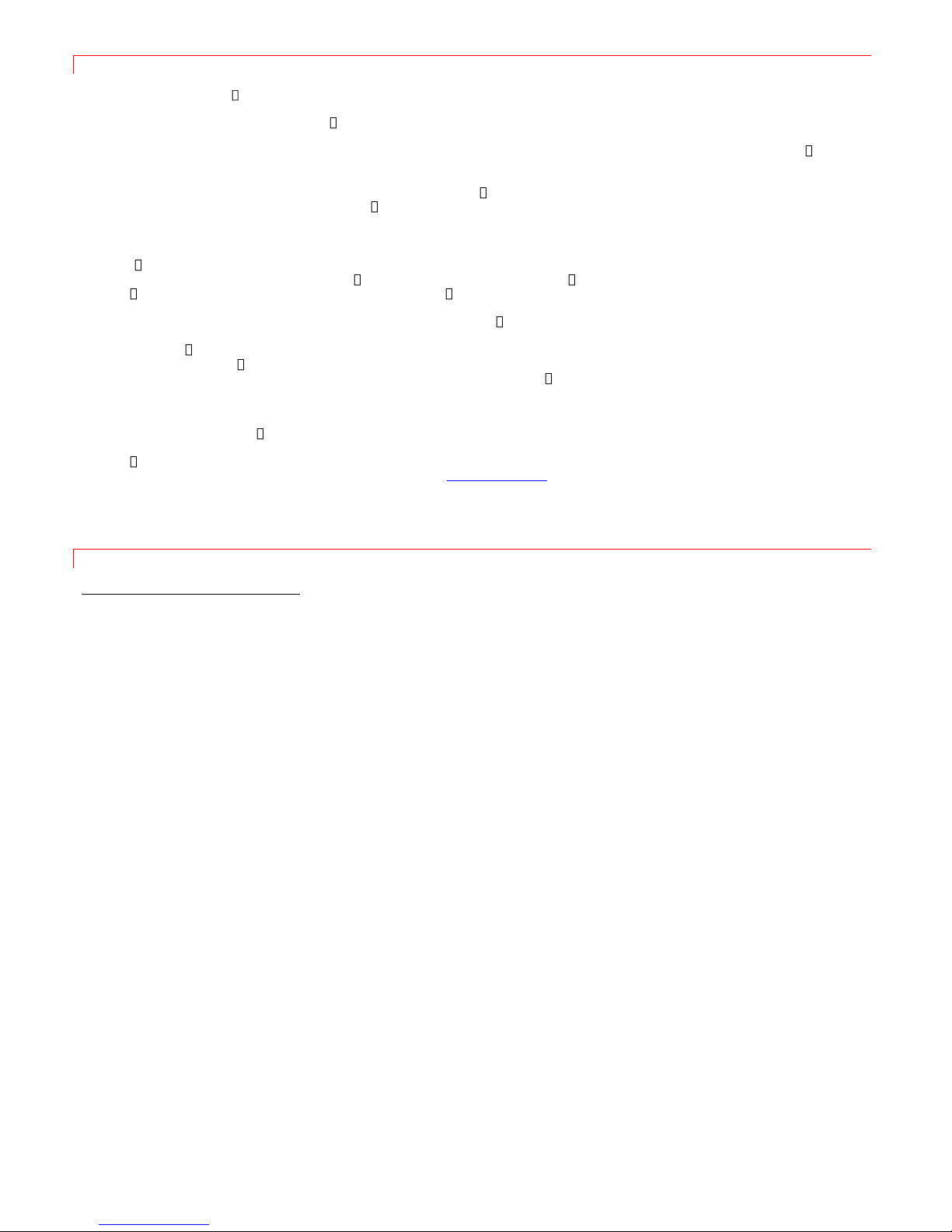
4. Attach the front wheels by positioning the brake disc between the brake calliper pads and inserting the axle. Attach the axle nut and tighten
the axle securely. (See Drawing 1).
5. Attach the rear derailleur hanger with the 3 countersunk screws provided. (See Photo 1).
6. Attach the rear derailleur (See Photo 1).
7. Attach the two Aluminium Seat Stay Adjusters to the rear part of the frame. Do not over tighten the bolts as the adjuster needs to move freely
(See Photo 2).
8. Kobra model only. Attach the rear brake calliper (See Photo 3).
9. Place the rear wheel into the frame. Insert the Quick Release and loosely attach the threaded end. Position the flag holder and tighten the
quick release (See Photo 4).
10. Insert the Boom fully into the frame (See Photo 5).
11. Attach the Chain Tubes and Pulley to the frame with the M8 Bolt, washers and nut provided. (See Drawings 2 and 3).
.
Note: If you have purchased the optional KMX Chain Tensioner then fit this now following the instructions provided with it.
Without the KMX Chain Tensioner the chain will be excessively loose and will need to be cut to length to suit the rider. (See Setting Up and Adjustment).
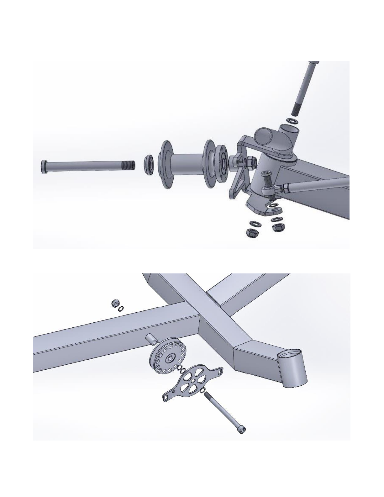
12. Feed one end of the chain through the short front chain tube, under the pulley, through the longer rear chain tube and around the rear
derailleur. Feed the other end of the chain through the front derailleur (Kobra model only), around the front chain ring and through the longer
chain tube. (See Drawing 3).
Attach the ends of the chain with the Quick Link Connector provided. (See Photo 6)
13. Kolt & Kobra Models - On the Right Side handlebar cut the untrimmed cable tie holding the rear gear cable and straighten the cable. Run
the cable along the frame inserting it into the cable clips as you go. (See Photos 7 and 8). Ensure the gear selector is in Number 8 and attach
the gear cable to the rear derailleur (See Photo 9). Attach the cable end.

PAGE 3
Kolt Model only – Secure the gear cable to the Steering Rod using 2 of the cable ties provided (See Photo 7).
Kobra Model only – On the Left Side handlebar cut the untrimmed cable tie holding the front gear and rear brake cables and straighten the
cables. Run the cables along the frame inserting them into the cable clips as you go (See Photo 8).
Attach the Rear brake cable to the brake calliper (See Photo 3). Attach the cable end.
Run the front gear cable along the frame inserting it into the cable clips as you go (See Photo 8). The front gear cable then passes through
the holes in the boom. (See Photo 12).
Ensure that the left hand gear changer is in Number 1 and attach the front gear cable to the front derailleur (See Photo 12).
Secure the brake and gear cables to the Steering Rod using 4 of the cable ties provided. (See Photo 8).
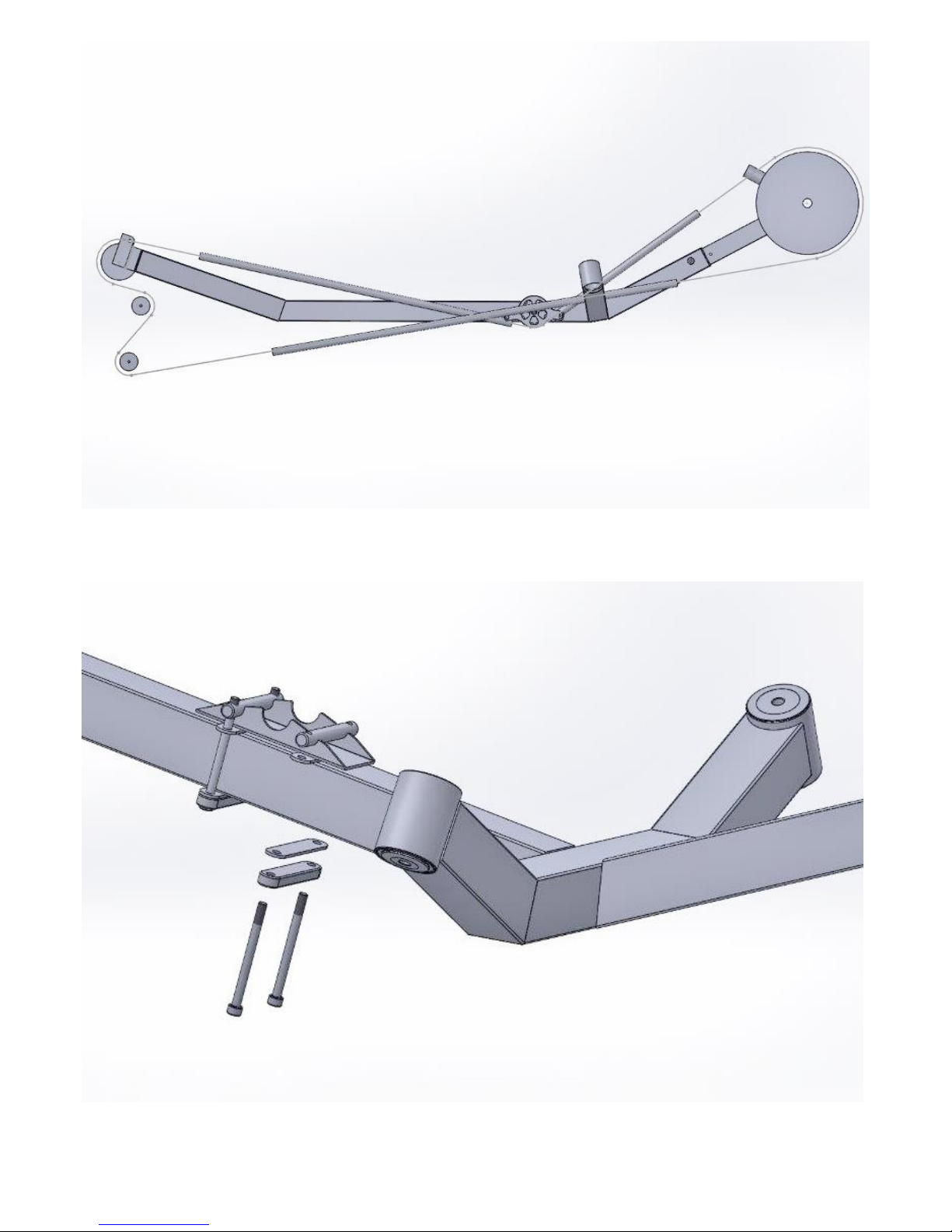
14. Kolt & Kobra Models - Position the seat on the frame. Slide the seat stays over the seat stay adjuster rods, insert the bolts into the middle
hole of the adjusters and attach the washers and nuts provided but leave loose until final set up. (See Photo 13).
Attach the bottom seat clamp to the frame but leave the bolts loose until final set up. (See Drawing 4).
15. Attach the pedals. Note that the left pedal has a left hand thread and the right pedal has a right hand thread.
16. Insert the Flag Pole into the flag holder.
17. Attach the rear mudguard to the top of the seat. (See Photo 14). NOW GO TO TRIKE SETUP – PAGE 10.
KMX KOYOTE MODEL
1. Carefully lift all the items from the box and remove the protective packaging.
2. Attach the right and left handlebar assemblies to the frame using the M8 bolts, nuts and washers. (See Drawing 1). Tighten the bolts securely
and insert the plastic end caps.
3. Attach the Steering Rod using the M8, bolts, nuts & washers. (See Drawing 1).
4. Attach the front wheels by positioning the brake disc between the brake calliper pads and inserting the axle. Attach the axle nut and tighten
the axle securely. (See Drawing 1).
5. Attach the rear derailleur hanger with the 3 countersunk screws provided. (See Photo 1).
6. Attach the rear derailleur (See Photo 1).
7. Attach the two Aluminium Seat Stay Adjusters to the rear part of the frame using the M8 x 25mm bolts and washers provided. Do not over
tighten the bolts as the adjuster needs to move freely (See Drawing 5).
8. Place the rear wheel into the frame. Insert the Quick Release and loosely attach the threaded end. Position the flag holder and tighten the
quick release (See Photo 4).
9. Insert the Boom fully into the frame (See Photo 5).
10. Attach the Chain Tubes and Pulley to the frame with the M8 Bolt, washers and nut provided. (See Drawings 2 and 3). Attach the Chain Tube
Strap. (See Photo 11).
.
Note: If you have purchased the optional KMX Chain Tensioner then fit this now following the instructions provided with it.
Without the KMX Chain Tensioner the chain will be excessively loose and will need to be cut to length to suit the rider. (See Setting Up and Adjustment).
11. Feed one end of the chain through the short front chain tube, under the pulley, through the longer rear chain tube and around the rear
derailleur. Feed the other end of the chain through the front derailleur around the front chain ring and through the longer chain tube. (See
Drawing 3).
Attach the ends of the chain with the Quick Link Connector provided. (See Photo 6)
12. On the Right Side handlebar cut the untrimmed cable tie holding the rear gear cable and straighten the cable. Run the cable along the frame
inserting it into the cable clips as you go. (See Photo 10). Ensure the gear selector is fully forward and attach the gear cable to the rear
derailleur (See Photo 9). Attach the cable end.
Secure the rear gear cable to the Steering Rod using 2 of the cable ties provided (See Photo 10).
On the Left Side handlebar cut the untrimmed cable tie holding the front gear cable and straighten the cable. Run the front gear cable along
the frame inserting it into the cable clips as you go (See Photo 10). The front gear cable then passes through the holes in the boom. (See
Photo 12). Ensure that the left hand gear changer is fully forward and attach the front gear cable to the front derailleur (See Photo 12).
Secure the gear cable to the Steering Rod using 2 of the cable ties provided. (See Photo 10).
13. Position the seat back on the frame and insert the two bolts through the centre holes in the lower seat frame (this position can be adjusted
later if required). Secure the seat back with the cupped spacers, washers and nuts provided. (See Drawing 5).
Attach the upper part of the seat stay to the top of the seat with the M8 x 25mm bolts and washers provided. (See Drawing 5). Slide the upper
seat stays over the adjuster rods lining up the hole in the upper seat stay with the fourth threaded hole in the adjuster rod (this position can be
adjusted later if required). Secure with the M8 x 20mm bolt, cupped spacers and washers provided. (See Drawing 5).
PAGE 4
14. Attach the pedals. Note that the left pedal has a left hand thread and the right pedal has a right hand thread.
15. Insert the Flag Pole into the flag holder. NOW GO TO TRIKE SETUP – PAGE 10.
DRAWING 1.
DRAWING 2.
PAGE 5
DRAWING 3.
DRAWING 4.

PAGE 6
DRAWING 5

PAGE 7
PHOTO 1. PHOTO 2.
PHOTO 3. PHOTO 4.
PHOTO 5. PHOTO 6.

PAGE 8
PHOTO 7 PHOTO 8
PHOTO 9 PHOTO 10

PAGE 9
PHOTO 11 PHOTO 12
PHOTO 13 PHOTO 14
PHOTO 15 PHOTO 16

PAGE 10
PHOTO 17 PHOTO 18
TRIKE SET UP
SEAT AND BOOM ADJUSTMENT - KOLT AND KOBRA MODELS
Slide the boom into the shortest position.
By using the different hole positions in the seat stay adjusters and the sliding seat clamp you can adjust the angle and position of the seat on
the frame.
Sit in the seat and adjust the boom length so that your right leg is straight with no bend at the knee when the right pedal is at its furthest point
and your heel is on the pedal (Photo 15). This will ensure that when you are cycling and you have the ball of your foot on the pedal, you will
have a slight bend at the knee (Photo 16). If you cannot reach the pedal then move the seat forward by extending the seat stays and sliding
the seat clamp forward on the frame. When you are happy with your final position, tighten the boom bolts, seat stay bolts and seat clamp
bolts.
Note: Never extend the boom beyond the etched line on the boom surface.
The lumbar support position is adjustable. Loosen the two clamps at the rear of the seat and move them up or down the seat frame to give
the most comfortable position.
SEAT AND BOOM ADJUSTMENT – KOYOTE MODEL
Slide the boom into the shortest position.
Sit in the seat and adjust the seat back position and boom length so that your right leg is straight with no bend at the knee when the right
pedal is at its furthest point and your heel is on the pedal (Photo 15). If you cannot reach the pedal then move the seat back into the forward
set of holes in the seat frame base. Adjust the seat angle by repositioning the seat stay bolts into an alternative threaded hole in the seat stay
adjusters. When you are happy with your final position, tighten the boom bolts, seat stay bolts and seat clamp bolts. (See Drawing 5).
HANDLE BAR SET UP – ALL MODELS
Sit in the seat and set the handlebars to a comfortable reach and angle, making sure your hands are clear of the tyres. Tighten the handlebar
clamps
Note: The maximum extension of the handlebars is 10mm.
CHAIN LENGTH ADJUSTMENT – ALL MODELS
Ensure that the chain is on the largest sprocket on the rear cassette and the largest front chain ring.
Remove the quick link and overlap the chain until the rear derailleur is pulled fully forward. Add four links to this position and then cut the
chain. You should end up with two “male” ends into which you can connect the quick link connector. (See Photo 18).
FRONT WHEEL ALIGNMENT
Refer to Photo 17. Place the trike on level ground and measure between the inside of the front tyres in the positions shown (A and B).
Loosen the lock nuts at either end of the steering rod (1 x Left & 1 x Right hand thread). Turn the rod until the measurement between the front
and rear of the tyres is equal. Now retighten the lock nuts.

PAGE 11
REAR DERAILLEUR SETUP

PAGE 12
FRONT DERAILLEUR SETUP

PAGE 13
BRAKE SETUP
4.0 Guidelines for safe use
Before using your KMX , please check that it is in good working order, that all bolts and screws are tight and that tyre pressure is as it should be.
Please also check the brakes.
The KMX is classified as a fully functional Trike recumbent. This means your KMX is allowed on the public roads, and complies with the European
General Products Safety Regulations. It has also been tested to all relevant sections of EN14764, the UK standard for bikes, and the CPSC for Bikes in
the USA.
Your KMX , like bicycles, Roller Blades, Roller Skates, Skateboards, Cars, Boats or any other moving vehicle, can cause injury. Exercise caution when
riding your KMX . Pay attention to street signs, be courteous to pedestrians and road users and by all means obey the law. Ensure that both hands are
on the handgrips and both feet are on the pedals at all times that the KMX is in motion.
For safety we recommend that an Adult should supervise any child using the KMX .
Adapt your speed always according to the prevailing conditions. Riding down a slope (at an angle,) the KMX could topple. Riding downhill will build up
a high speed, so please take note of a longer braking distance.
We advise that whilst riding the KMX the rider wears proper protection, such as a helmet and gloves while riding.
Ensure that both hands are on the handgrips and both feet are on the pedals at all times that the KMX is in motion.
Do not take bends at a too sharp an angle; this could cause the KMX to topple.
Check the tyre pressures regularly.
In case of improper use of your KMX neither the manufacturer nor the dealer can be held responsible.
The KMX cannot be used near staircases, swimming pools or any other water. Staircases should be shielded off, to avoid riders being able to ride up
or down.
Engage the handbrake button on the rear brake lever to lock the rear brake before leaving the KMX unattended.
Colliding and/or other stunts increase the chances of injury, and damage to your KMX .
In this event, any damage cannot be reclaimed from the manufacturer or the dealer.
Do not place any unnecessary objects on or near the brake handles.
Clothes and limbs could get caught in rotating parts and/or hinge points. Avoid loose clothing like scarves, laces etc., as these could cause accidents.
Clothes could get soiled and/or damaged.
Avoid contact with the wheels whilst the KMX is being driven.
This users’ manual contains size indication guideline. However the owner is responsible for judging whether or not the KMX is suitable for each rider,
and that his or her size is appropriate.
A helmet is not compulsory, but in the interests of safety it is advisable.
Make sure that the seat and sliding boom is in the correct position, for safe use.
Do not let the user mount or dismount the KMX whilst in motion.
Do not let the user drive in the dark without lighting.
Only one person can ride the KMX at any time. Do not overload your KMX .
The maximum loading is 95kg for off road riding and 130kg for on road riding.
Do not attach an engine or any other unapproved attachments to the KMX .
Do not allow your KMX to be pulled by any other vehicle.
KMX Karts Ltd, the suppliers of the KMX and/or the manufacturer do not accept any liability for any injury or any other damage sustained and any
incurred costs as a result of (wrongfully and/or impropriate) use of the KMX .

PAGE 14
5.0 Maintenance
Every time before you ride:
Approx. time: 4
minutes.
Inflate tyres to correct pressure.
Replace tyres if worn.
Test Brakes for correct operation.
Check bolts on both seat and front boom to insure
they are tight.
Inspect tyres for damage.
Every week: (in addition to above).
Approx. time: 2
minutes.
Quickly wipe frame down and inspect for cracks.
Check bolts and screws are fastened tight.
Test brakes and shifting for adjustment.
Inspect seat clamps and boom clamps for cracks
and insure adequate tightness.
Every month or after your KMX gets wet. (In addition to above).
Immediately after riding:
Approx. time: 30
minutes.
Dry bike with towel; pedal the drive train with your
hands while lifting the rear wheel to spin water out of
rear bearing surfaces, cog set, chain, etc.
Wash bike completely with soap and water. Dry bike,
spin wheels and cycle drive train to expel water.
Apply chain lubricant and wipe off excess.
Apply lubricant to derailleur pivots and brake pivots.
DO NOT get lubricant on tires or wheel/rim braking
surfaces.
Inspect wheels, hubs, steering set and bottom
bracket adjustment and tightness.
If you stick to this maintenance schedule it is unlikely you will ever have a serious maintenance problem or major mechanical malfunction during a ride.
6.0 Guarantee conditions
The KMX owner can only claim under the guarantee by showing the original purchase receipt together with the completed guarantee certificate.
The owner of the KMX can claim the following guarantee with the acceptance of the following restrictions:
• One year from date of purchase on the frame (regular use);
• All wear and tear parts (for example chain, crank, chain guides, tyres etc.) are not covered by the guarantee.
• The guarantee only applies for material/construction errors of the KMX and/or parts thereof.
The guarantee expires in the following situations:
• The KMX has been handled without due care, has been involved in an accident, or when non- KMX approved parts have been fitted.
• The KMX has not been assembled as per instructions and/or not correctly maintained.
• Technical repairs of the KMX are not executed professionally.
• Parts fitted afterwards do not match technical specifications of the KMX or no original KMX parts have been used and/or are not fitted correctly.
• Deficiencies due to climate, like rust, cracks in the rubber or usual weathering of the coatings.
• The KMX is used for rental and/or otherwise used by non-specified users.
All claims under the guarantee for the KMX have to be accompanied by a copy of the guarantee certificate.
The guarantee certificate needs to be completed and should contain the following details:
• Name and address of the owner
• Date of Purchase
• Description of parts for which a claim is being made under the guarantee.
The final decision whether or not the broken/damaged parts falls under the guarantee is made by an approved KMX engineer.
In case the guarantee request does not apply to the repair, all costs have to be paid by the owner.

PAGE 15
7.0 Guarantee certificate
GUARANTEE CERTIFICATE
(Purchaser copy)
Date of Purchase:
Type/Model KMX :
Colour:
Signature buyer:
GUARANTEE CERTIFICATE
(KMX Karts COPY)
Date of Purchase:
Type/Model KMX :
Colour:
Retailer KMX :
Name:
Address:
Town/City:
Postal-code:
Country:
Date of Birth:
Signature purchaser:
Send to: KMX Karts Ltd
Unit E2, Knowle Village Business Park,
Mayles Lane,
Fareham, Hampshire
PO17 5DY
United Kingdom
 Loading...