

KMW Communications PAC-I User Manual
KMW Communications
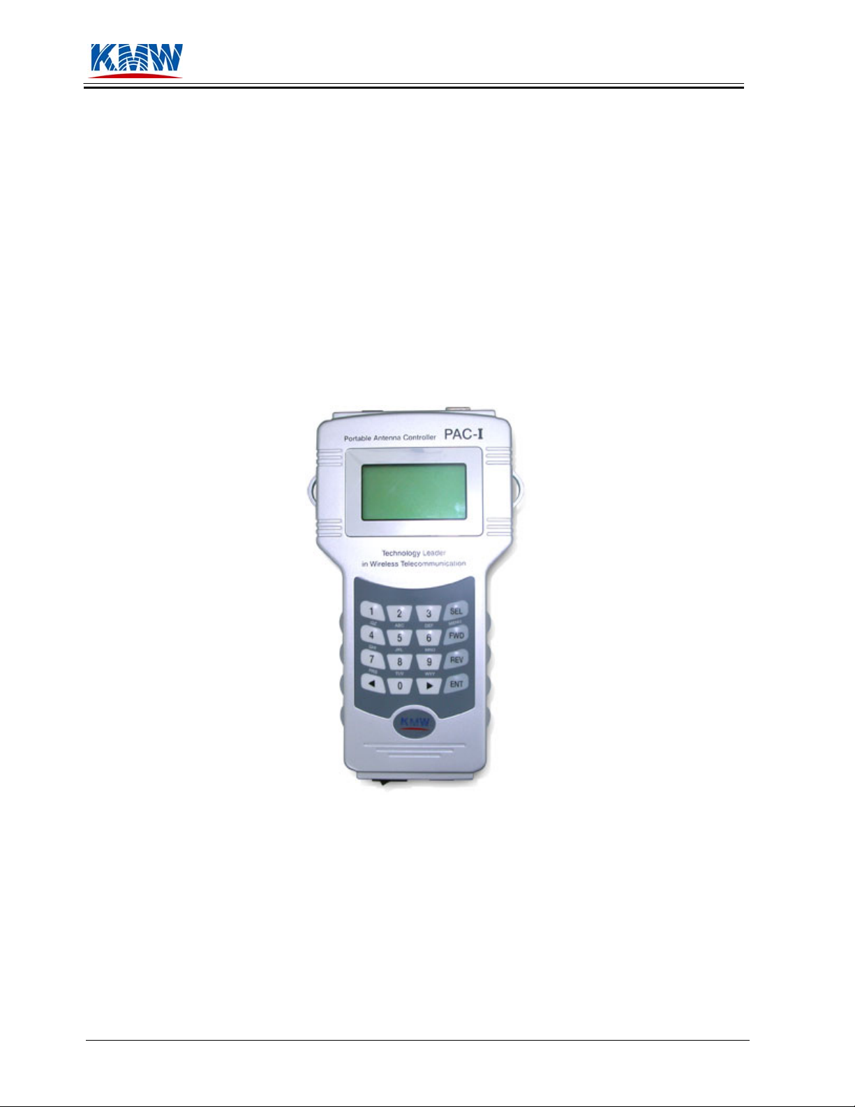
Portable Antenna Controller
(PAC-I™)
User’s Guide
Document: KC-50-0001-03
10/17/2005
Page 1 of 34 Portable Antenna Controller KC-50-0001-03
User’s Guide 10/17/05

KMW Communications
2004 KMW Communications, Inc.
All
rights reserved
No part of this document may be reproduced or transmitted in any form or by any means,
electronic or mechanical
KMW hereby authorizes its customers to make
customer’s own computers for use in conju
Information in this document is subject to change without notice. KMW assumes no liability for
omissions
or inaccuracies in this document, or from the furnishing or use of the information
herein. KMW reserves the right to
assume any
liability arising out of the applications or use of any product described herein.
, for any purpose without the express written permission of KMW.
copies of this documentation in CD-ROM form to
nction with the products described herein.
make changes to any products described herein and does not
This docu
that is provided
described herein. If the
contract with KMW, or is not otherwise inten
information in it, you are hereby notified tha
derogation of KMW’s proprietary interests
document, please return it immediately to KMW
ment and the information in it is the proprietary and confidential information of KMW
by KMW to its customers pursuant to a contract for the purchase of the products
possessor of this document is an entity or individual not party to a sales
ded by KMW to receive this document and the
t such possession is unauthorized and is in
. If you are in unauthorized possession of this
at the address contained herein at KMW’s cost.
Revision History
Date Version Description
06/06/2004 KC-50-0001-Draft Version Initial production release of the portable
antenna contr
controlled anten
07/20/2004 KC-50-0001-01 Production release
10/22/2004 KC-50-0001-02 Revision update
04/13/2007 KC-50-0001-03 Company information change
If you have questions or comments about the content of this document, please contact:
oller (PAC-I) for KMW remote
na products.
KMW
Communications
1521 East Orangethorpe Ave.
Sui
te A.
Fullerton, CA 92831
714-
895-3659
http://w
support@kmwcomm.co
Page 2 of 34 Portable Antenna Controller KC-50-0001-03
User’s Guide 10/17/05
ww.kmwcomm.com
m

KMW Communications
9. Troubleshooting Guide
9.4. Description of Alarm Codes
Item Code (Hex) Description
Same Code Over Count 0x01 Current position was detected after a fixed number of
trials. Check torque or control voltage.
Open Code Over Count 0x02 Open value was detected after a fixed number of trials.
Check connections between Bias-T, cable, and antenna.
Unknown Code Detection 0x04 Unknown position value was detected. Failure due to
motor box encoder inside antenna, Bias PCB, Bias-T, AD
converter of the controller, etc.
Maximum Limit Detection 0x08 Out of control range. Failure due to motor malfunction
or incorrect actuating voltage.
Minimum Limit Detection 0x10 Out of control range. Failure due to motor malfunction
or incorrect actuating voltage.
Next Code Not Detection 0x20 Control position failure. Failure due to insufficient
torque, motor encoder, etc.
Miss Path Detection 0x40 Failure in control path relay, controller, incorrect position
of motor during antenna assembly, etc.
Note: The above alarms include failures that may not be repaired by end-users. Contact KMW
Technical Support for further assistance.
9.5. General Information
• PAC reset while operating:
This may be caused by insufficient amount of remaining battery power. Check the battery level
and recharge if necessary.
• Recovering from Alarm:
For any alarms listed above (Table 6-1), the PAC automatically recovers from the alarm. If an
alarm continues to appear, user may try to recover from the alarm by pressing ‘ENT’ key after
alarm appeared. If the alarm continues after the manual recovery process, contact KMW Technical
Support for further assistance.
Page 32 of 34 Portable Antenna Controller KC-50-0001-03
User’s Guide 10/17/05

KMW Communications
Table of Contents
1. Preface___________________________________________________________5
1.1 Purpose_____________________________________________________________5
1.2 General Information___________________________________________________5
1.3 Related Documents____________________________________________________5
2. Overview of Portable Antenna Controller Kit _____________6
2.1 Controller Kit Packing List _____________________________________________6
2.2 Controller Functions___________________________________________________7
2.3 PAC-I Operating Requirements __________________________________________7
3. Overview of PAC-I ____________________________________________8
3.1 External View________________________________________________________8
3.2 Part Description ______________________________________________________9
4. Preparation ____________________________________________________10
4.1 PAC-I Packing List __________________________________________________10
4.2 Power Supply/Battery_________________________________________________10
4.3 Connecting PAC using Control Cable ____________________________________11
4.4 Connecting Optional PAC Communication Cables__________________________11
4.5 Connecting Optional PAC Communication Cables__________________________12
5. Operating PAC-I ______________________________________________14
5.1 Key Functions_______________________________________________________14
5.2 Verifying User ID and password ________________________________________15
5.6. Antenna Beam Direction Control________________________________________19
6. PAC Menu Structure__________________________________________22
6.4. Menu Diagram ______________________________________________________22
7. PAC PC Application User’s Guide__________________________23
7.4. Operating Environment _______________________________________________23
7.5. Program Installation and Execution______________________________________23
7.6. Start-up Window ____________________________________________________23
7.7. Getting Started ______________________________________________________25
8. Cautions _______________________________________________________31
9. Troubleshooting Guide _______________________________________32
9.4. Description of Alarm Codes____________________________________________32
9.5. General Information__________________________________________________32
10. Portable Antenna Controller Specifications_______________33
Page 3 of 34 Portable Antenna Controller KC-50-0001-03
User’s Guide 10/17/05

KMW Communications
11. Technical Support_____________________________________________33
Reader Survey Form ____________________________________________________34
Page 4 of 34 Portable Antenna Controller KC-50-0001-03
User’s Guide 10/17/05

KMW Communications
1. Preface
1.1 Purpose
1.1.1 The purpose of this document is to explain how to operate PAC-I (Portable Antenna
Controller – First Edition of Controller Series: herein “PAC-I”) for antenna beam control of
KMW’s adjustable antennas (1-Way EDTA, Hybrid 2-Way Antenna).
1.1.2 The main use of this portable, easy-to-carry controller is to control vertical and horizontal
beam width of KMW’s adjustable antennas.
1.1.3 The purpose of PAC-I is to increase the effectiveness of base station operations by offering
easier and cost-effective network optimization through remote control capability of antenna
beam direction control.
1.2 General Information
1.2.1 By incorporating RS-485/422 communications interface, PAC-I is designed to be interoperable
with the base station systems.
1.2.2 By incorporating RS-232 communications interface, PAC-I supports the value-added features
such as user registration, antenna beam control data log management, firmware download,
etc.
1.2.3 PAC-I is designed to be portable and user-friendly and features Graphic LCD Screen and 4×4
key function.
1.3 Related Documents
1.3.1 PAC-I Specifications
1.3.2 Communications protocol between PAC and PAC PC Application software (KMW
proprietary protocol)
Page 5 of 34 Portable Antenna Controller KC-50-0001-03
User’s Guide 10/17/05
KMW Communications
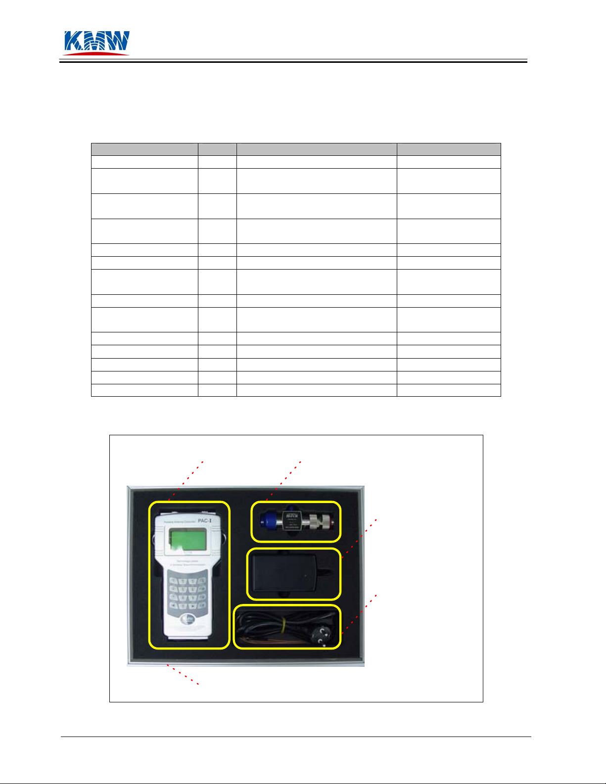
2. Overview of Portable Antenna Controller Kit
2.1 Controller Kit Packing List
Items Qty. Size Part Number
PAC-I KIT 1 - KMDAN0104000
PAC-I 1
Rechargeable Battery
(included in PAC-I)
AC/DC SMPS
Adaptor
AC Power Cable 1 250V, 2M XMJ0MD028ZA
AC Power Plug 1 220V to 110V PXZZMD0281A
Control Cable 1
RS-232 Cable 1 DSUB(M) to DSUB(F), 2 meter WA01MD0519A
Bias-Injector with
DIN-Barrel Adaptor
Shoulder Strap 1 2 meter PXZZMD0282A
Carrying Case 1
User guide 1 - KC-50-0001-02
Program CD 1 PAC PC Application -
Adaptor 1 DIN(M) – DIN(M) KAD828211000
1
1
1 - KASCTR182019
Refer to product specification in
Section 10
3.7V, 3CELL(11.1V, 1.5A)
LI-POLYMER
Input: 100~240V, 50/60Hz 1.5A
Output: 19VDC, 3.68A 70W
SMA(M)-to-SMA(M),
RG316Type, 2 meter
410×310×125 mm
Figure 2-1. Inside View of PAC Kit
KMDAN0103000
PXZZMD0280A
XW01MD028ZA
KCA051011056
GC91MD0519A
PAC-I Bias Injector
AC/DC SMPS
Adaptor
AC Power Cable
& Control Cable
Carrying Case
Page 6 of 34 Portable Antenna Controller KC-50-0001-03
User’s Guide 10/17/05

KMW Communications
2.2 Controller Functions
• Vertical (electrical) and/or horizontal (mechanical) antenna beam control
• Antenna model (EDTA 1-way, Hybrid 2-way) and sector selection
• User ID and password input for security protection
• Base station ID input for history log
• Data interoperability between PAC and PAC PC Application
o Registration of user ID and password
o Registration of base station ID
o Antenna control data upload and management
o Firmware (F/W) download
• Power detector and indicator
o AC/DC Adaptor connection detector
o Battery level indicator
• Time and date display
• Automatic speed control of antenna beam controlling motor
• Automatic recovery of antenna control alarm
• Various communications protocol support
o RS-232: PAC-I ↔ PAC PC Application
o RS-485/422: PAC-I ↔ Base station systems
2.3 PAC-I Operating Requirements
• PAC-I allows antenna control of KMW’s remotely adjustable antennas only.
• User has the basic operations knowledge of the KMW current antenna products. For new antenna
models KMW develops in the future, user may need to update the software.
• PAC-I uses rechargeable battery as its main source of power, and user should frequently check
and charge the battery to maintain its optimal power level.
• Although PAC-I has Super User ID and BTS ID already stored in it, it is advised that the user
registers its own user ID and BTS ID using PAC PC Application software in order to secure and
manage the data effectively.
Page 7 of 34 Portable Antenna Controller KC-50-0001-03
User’s Guide 10/17/05
KMW Communications
3. Overview of PAC-I
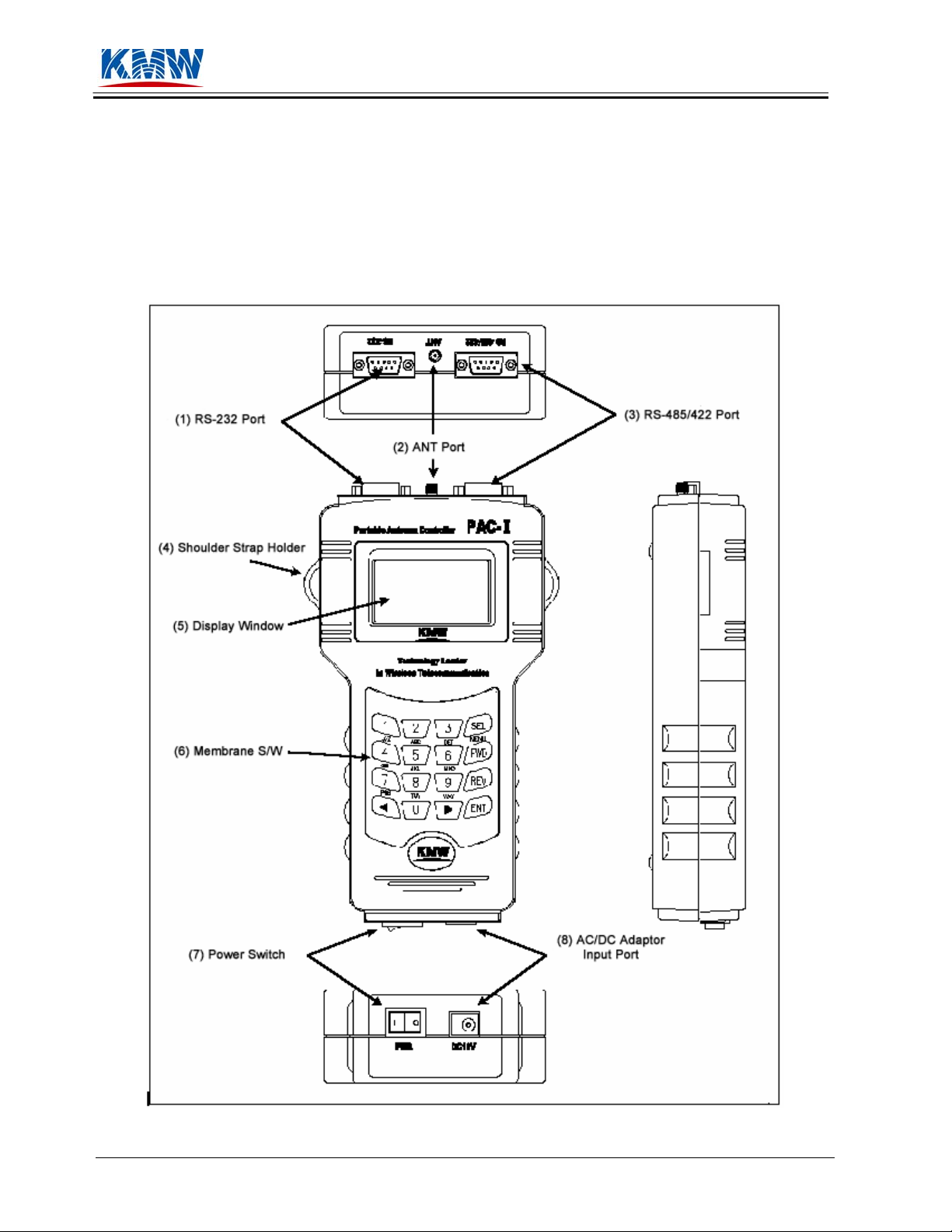
3.1 External View
Figure 3-1. External View of PAC-I
Page 8 of 34 Portable Antenna Controller KC-50-0001-03
User’s Guide 10/17/05

KMW Communications
3.2 Part Description
• RS-232 Port:
This is for communication between PAC-I and PAC PC Application software (RS-232
communications standard) installed on a PC.
• ANT Port:
This is for antenna beam control. Connect DC input port of Bias-T and ANT Port with Control
Cable.
• RS-485/422 Port:
This is for communication between PAC-I and base station systems. For its use, protocol should
be discussed with the customer.
• Shoulder Strap Holder:
Used to hold shoulder strap.
• Display Window:
Displays the date, time, battery level, and antenna control information and status.
• Membrane S/W:
This is the keypad to input antenna control information. 4×4 Matrix Key Function is used to
enhance easy operation and support multiple functionalities PAC-I offers.
• Power Switch:
Switch for power supply.
• AC/DC Adaptor Input Port:
This is the input port for outside power supply. It connects PAC-I to outside power supply in case
the built-in battery dies or does not have enough power charged to operate PAC-I.
Page 9 of 34 Portable Antenna Controller KC-50-0001-03
User’s Guide 10/17/05
KMW Communications
4. Preparation
4.1 PAC-I Packing List
User should make sure that there is no missing part from PAC-I Kit to prevent any control failure or
error during operation. (Refer to Section 2.1)
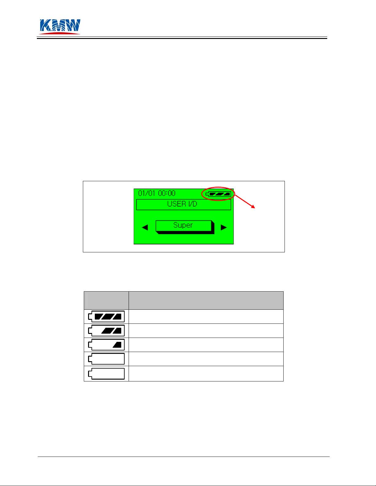
4.2 Power Supply/Battery
After turning on the power switch of PAC-I, user should check the battery indicator located on the top
right corner of LCD screen to verify if the battery is charged sufficiently to operate PAC-I. If this
indicator blinks every second, user needs to recharge the battery.
Figure 4-1. View of LCD Screen
Battery
Indicator
Figure 4-2. Battery Level Indicator
Battery
Indicator
Power Level
75% to 100% full
50% to 75% full
25% to 50% full
Below 25% full
If power level is below 20%, the indicator blinks every
second to warn the user to recharge.
Page 10 of 34 Portable Antenna Controller KC-50-0001-03
User’s Guide 10/17/05
 Loading...