

Page 1
Operation Manual
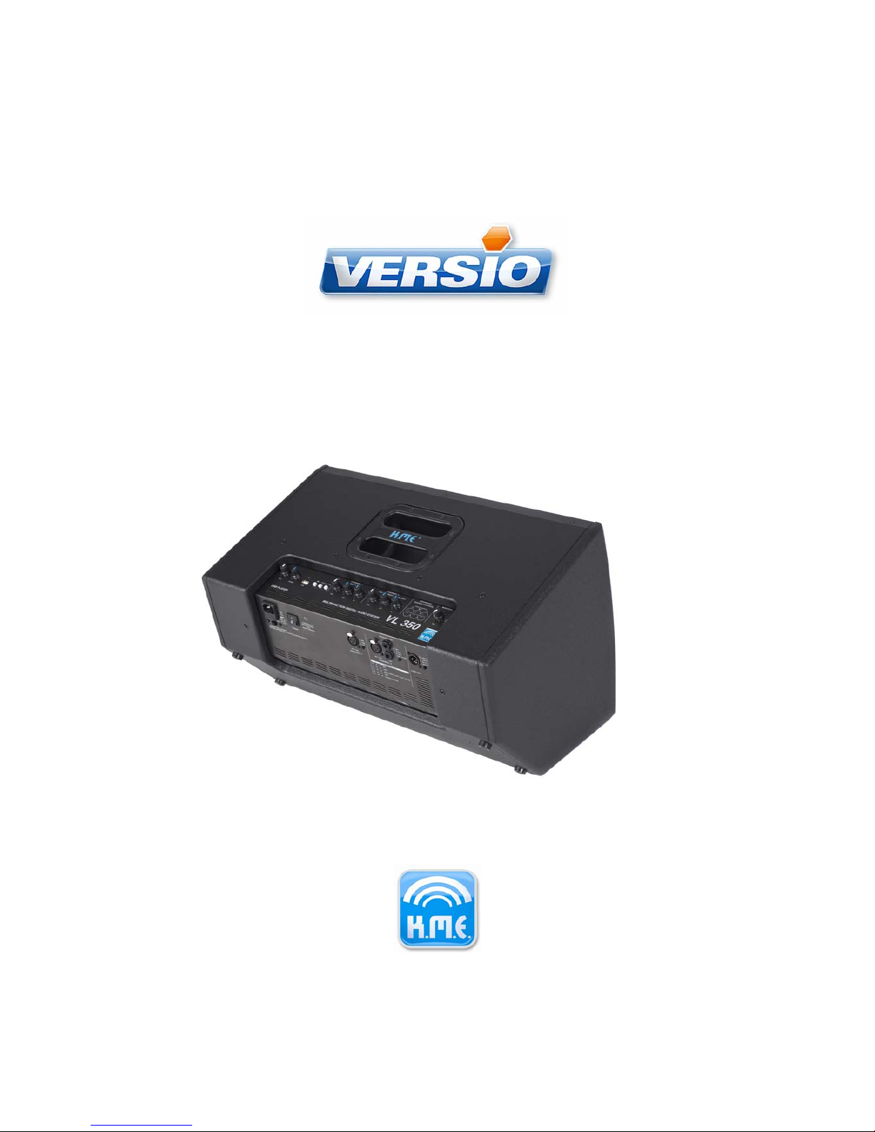
VL340
VL350
Page 2

Thank you for choosing K.M.E.! The VERSIO series has been consequently developed to meet
portable requirements.
With these compact and ergonomic loudspeaker systems you will be able to master your reinforcement situations in a very flexible manner (main PA, monitoring, fill system).
This manual provides helpful advice to guarantee a safe long-term operation. Please take the
time to get accustomed to the technical properties of your new PA system prior to putting it into
operation. For questions you may either contact your local dealer or the K.M.E. Support.
Within our extensive production processes we only use selected materials and components of
best quality. Share with us the enthusiasm for good sound. The K.M.E. team wishes you joy and
success using your new PA-system!
Table of contents
1 FEATURES......................................................................................................................................................3
2 INPUT PANEL AND CONTROLS...................................................................................................................4
3 QUICK SETUP................................................................................................................................................7
4 OPERATION....................................................................................................................................................9
4.1 Speaker placement.................................................................................................................................9
4.2 General Information..............................................................................................................................10
4.2.1 Handling the tiltable flange......................................................................................................................................................10
4.2.2 Button Lock..............................................................................................................................................................................11
4.2.3 Automatic operating state storage...........................................................................................................................................11
4.2.4 Avoidance of Ground-Loops....................................................................................................................................................12
4.2.5 Peak / limit indicator................................................................................................................................................................12
4.3 Connecting sources and setting the input sensitivity......................................................................13
4.4 Setting channel and master volume...................................................................................................16
4.5 Tone Control Operation........................................................................................................................17
5 USB player tone control................................................................................................................................................................17
5.0.1 Adaptive tone control of Channel 1 and 2...............................................................................................................................17
5.0.2 Advanced tone control matrix display ....................................................................................................................................20
5.1 USB audio playback.............................................................................................................................21
5.1.1 Controls...................................................................................................................................................................................21
5.1.2 USB-LED status information...................................................................................................................................................21
5.1.3 Supported audio file formats...................................................................................................................................................22
5.1.4 Playing audio files...................................................................................................................................................................22
5.1.5 Playback order........................................................................................................................................................................22
5.1.6 Folder change..........................................................................................................................................................................23
5.1.7 Usage of playlists....................................................................................................................................................................24
5.1.8 Folder change when using playlists........................................................................................................................................25
5.1.9 Creating playlists.....................................................................................................................................................................25
5.2 Selecting the Line Out signal..............................................................................................................25
6 FIRMWARE UPDATE...................................................................................................................................27
7 SAFETY PRECAUTIONS.............................................................................................................................27
8 TROUBLE SHOOTING.................................................................................................................................28
9 SPECIFICATIONS.........................................................................................................................................29
10 EC DECLARATION OF CONFORMITY.....................................................................................................30
11 WARRANTY................................................................................................................................................31
12 DISPOSAL OF OLD APPLIANCES............................................................................................................31
2
Page 3

Note:
This Manual relates to both VL340 and VL350, whose electronics unit don't differ in their operation. For simplicity reasons the term „VL3x0“ is used to refer to both models.
1 Features
USB Player
•
Playback of MP3 and WAV files requires an USB stick only
Channel
1
•
1 XLR input with switchable Phantom Power. Suitable for use with microphones or line
outputs.
Channel 2
•
1 XLR input (labeled „I“), suitable for use with microphones or line outputs.
•
2 6,3mm jacks (labeled „II“ and „III“) provide connection for unbalanced sources such
as Keyboard stereo outputs.
•
The High-Z instrument jack III is especially tailored to the amplification of pick-up
equipped instruments. Separate modes for Acoustic Guitar and Electric Guitar allow
an easy and effective tone control.
Line Out
•
Selectable Line-Out signal. The routing matrix provides the following combinations:
- channel 1 only,
- sum of Channel 1 and Channel 2, and
- sum of USB Player output, Channel 1 and Channel 2.
Enclosure
•
The enclosure design of the VL3x0 enables its application as floor monitor as well as a front
PA-s ystem.
•
When used as front PA-system the sound dispersion can be aligned to the audience area by
adjusting the angle of the flange.
•
In floor monitor operation a convenient sound radiation is achieved through the 35° floor
stand angle.
3
Page 4
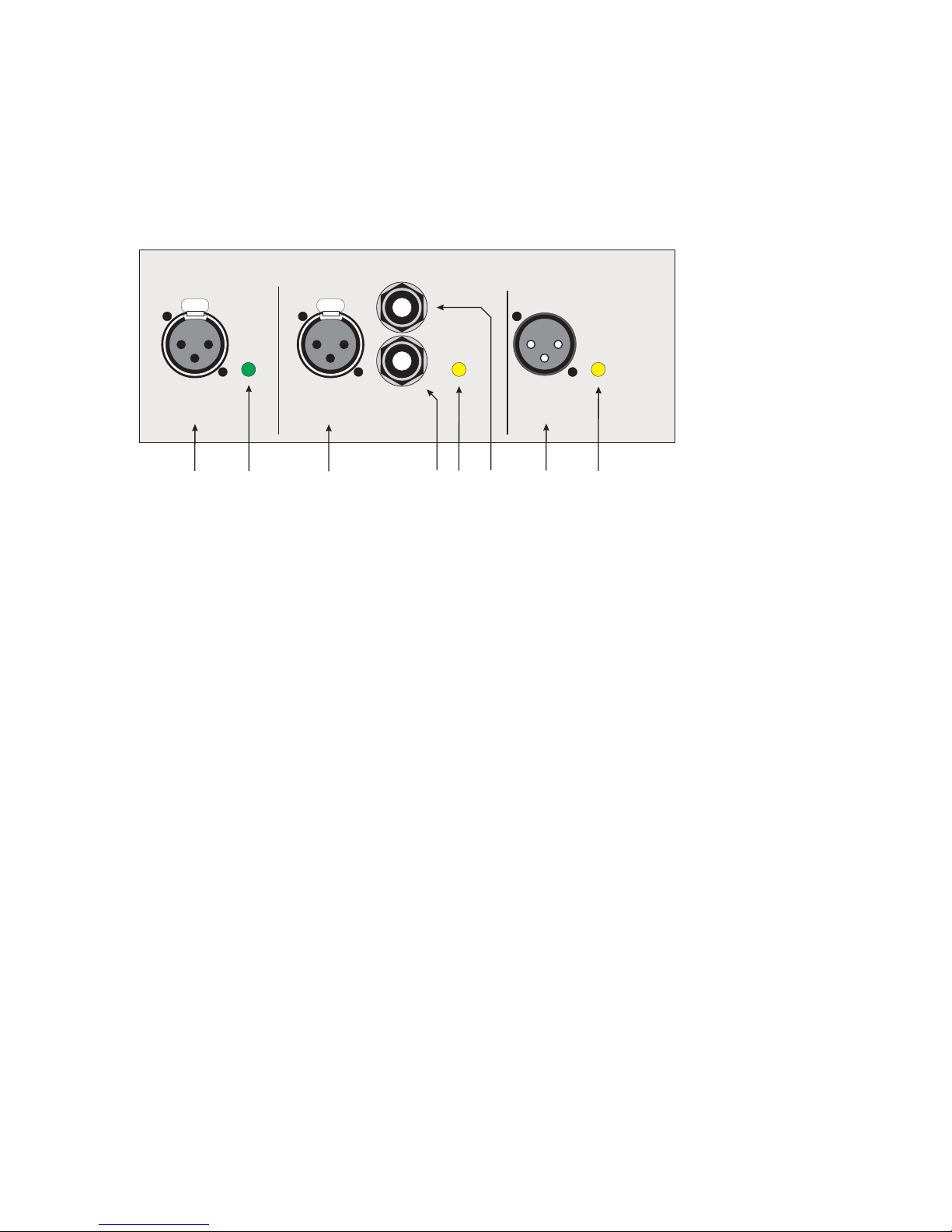
2 Input panel and controls
To gain a quick overview the following section depicts the arrangement of the input connectors
and the controls' mode of operation.
Input Section
Channel 1
1. Balanced microphone / line input, switchable P48-supply, XLR connector
2. Input mode selector:
- sets Input sensitivity
- activates P48-supply
- automatically adapts tone control characteristics to intended input source)
Channel 2
3. Balanced microphone / line input, XLR connector
4. Balanced / unbalanced Line input, 6,3mm jack
5. Input mode selector:
- sets Input sensitivity
- activates P48-supply
- automatically adapts tone control characteristics to intended input source)
6. High-Z unbalanced Line / Instrument input, 6,3mm jack
Line-Out
7. Balanced Line Out, XLR connector
8. Line Out signal selector
4
Illustration 2.1: Input and Line Out connectors
CHANNEL 1 CHANNEL 2 LINE OUT
SPLIT L/R
-
INSTRUMENT/LINE
I
II
III
LINE
MIC/LINE MIC/LINE
G
Y
R
:
:
:
MIC
A-GUIT
E-GUIT
LINE / OTHER
-
G
Y
R
:
:
:
::
G
Y
R
:
:
:
LINKCH1
LINKCH1+CH2
MASTER POSTP48
MIC
LINE
1. 2.
3.
7.
4.
5.
6.
8.
Page 5
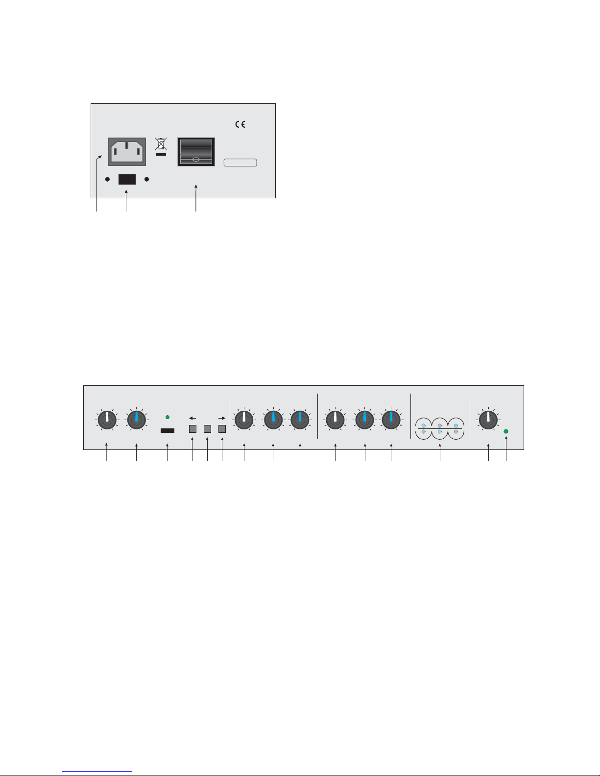
Power socket and power switch
9. Mains power switch
10. IEC mains socket
11. Ground / Free switch – separates the input connectors' ground from the chassis to allow
ground loop avoidance
Front panel
5
Illustration 2.3: Front panel controls
Illustration 2.2: Mains power section
POWER
KLINGENTHALER
MUSIKELEKTRONIK
GmbH
MADE IN GERMANY
WARNING! THIS EQUIPMENT MUST BE EARTHED!
PULL POWER PLUG BEFORE OPENING!
230V ~AC
50-60 Hz
P= 600W
FREE
GND
10.
11.
9.
VOL VOL VOL VOL
STATUS
AMP LIMIT
CH PEAK
USB
PLAY/ II
SOUND LO LO
HI HI
LO MID
FREQUENCY
HI
CHANNEL 1
MIC /LINE INSTRUMENT /LINE / MIC
CHANNEL 2
ADVANCED
SOUND CONTROL
MASTER
12.
13.
14.
15.
16.
17.
18.
19.
20. 21. 22. 23.
25.
24.
26.
Page 6

USB Player
12. USB playback volume
13. Tone control
14. USB connector and USB status LED
USB status LED Information
continuous green USB media has been successfully detected
flickering green audio is being played
flashing orange search in progress
continuous orange no valid audio files have been found
continuous red failed to detect USB media / over current
15. Playback control: previous
16. Playback control: play / pause
17. Playback control: next
Channel 1
18. Channel volume
19. Tone control: bass
20. Tone control: treble
Channel 2
21. Channel volume
22. Tone control: bass
23. Tone control: treble
Advanced Sound Control
24. LED matrix signifying the areas affected by the tone controls
Master
25. Master volume
26. Operating status LED
Operating status LED Status
green normal operation
orange signal peak exceeded
red over-temperature / overload
6
Page 7

3 Quick Setup
These few hints will help you setting up your new PA system in an instant:
Apply mains power
•
Ensure that the power switch rests in its “OFF”-position (“0” is pressed down on the rocker)
•
Apply mains power via the IEC connector (10)
Caution: observe the appropriate voltage range of 85 – 265V / 50-60 Hz!
•
Power up the unit by turning on the mains switch (9). The operation status – LED (26) should
turn green.
USB player
To use the USB player insert an USB stick containing the media to be played.
USB Player operation:
•
starting the playback: Press „Play / Pause“ (16).
•
pausing the playback : again, press „Play / Pause“ (16).
•
(12) sets the playback volume.
•
Skip song: press → next (17) or ← previous (15).
•
Change folder: long press on → next (17) or ← previous (15).
Connect audio sources
•
See Illustration 2.2. for connection possibilities.
•
Set input sensitivity / mode to meet the requirements of the connected sources. Pressing
the input mode buttons (2), (5) toggles the input modes.
The labels near the input mode buttons show the association of the selected mode with the
displayed color (see Illustration 2.1). All modes and their fitting application are summarized by
the table below:
7
L To avoid pop noise when connecting the sources low down the Master (25) or Chan-
nel-Volume (18), (21) in advance.
L If playback is impossible the USB-LED will light red.
Either no valid media could be found or the USB stick could not be detected. See Chapter 5.1.3
Supported audio file formats for further information.
Page 8
Channel 1
Button color Mode Application
G = green
MIC Microphones
Y = yellow
LINE Line-level signals, e.g. Mixing Console Outputs, CD-Players
R = red
P48 (MIC) Microphones requiring Phantom Power
Channel 2
Button color Mode Application Associated Input
G = green
MIC Microphones XLR I
Y = yellow
A-GUIT Acoustic Guitars 6,3mm Jack II
R = red
E-GUIT Electric Guitars 6,3mm Jack II
off LINE / OTHER Line-level signals, e.g. Mixing Con-
sole Outputs, CD-Players
6,3mm Jack I
•
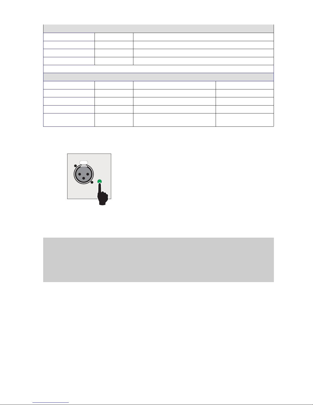
If necessary, you may switch on Phantom Power by keeping the input mode button for Channel 1 pressed until it lights up red (as seen in Illustration 3.1). Similarly, switching off requires
another long press.
•
Start by increasing Master Volume (26) to approximately 13 'O clock and subsequently set the
Channel Volume (19), (22).
A good starting point can be found between 12-14 'O clock position.
While the setting in 12 'O clock position corresponds to a gain of roughly 0 dB in LINE-Modes,
the modes MIC and Instrument mode offer about 10-30 dB gain.
•
Increase the gain should you not be able to hear the signal at high Master Volume setting.
Follow the guidelines in Chapter 4.3 , if no reasonable output signal is made audible.
8
Illustration 3.1: Selecting the input mode
CHANNEL 1
MIC / LINE
G
Y
R
:
:
:P48
MIC
LINE
L
Enabling / disabling the button lock
In case all buttons (2), (5), (8) are flashing red when being pressed they need to be unlocked first
in order to be operable. Hold Channel 2 mode button (5) and the Line-Out selector (8) buttons
simultaneously until Channel 1 button (2) is flashing. To lock the buttons again repeat this last
described step. Further explanation follows in Chapter 4.2.2 .
Page 9

•
The Line-Out signal can be selected by pressing (8). See chapter 5.2 for complete description.
Now the VL3x0 is ready for operation!
4 Operation
4.1 Speaker placement
•
A few hints on feedback prevention:
•
When placing the microphone make sure its sonically least sensitive side points in the direction of the speakers highest sound pressure. In the case of the commonly used cardoid
microphones this will be given if the microphones' diaphragm is opposing the loudspeakers'
front side in 90° of angle
In other cases such as microphones exhibiting bidirectional characteristics whose backward
sensitivity is not sufficiently low a slightly sidewards turned placement of the speakers is
recommendable.
•
Keep the microphones' speaking distance low to minimise the needed gain. Maximise the distance between microphone and loudspeakers. Also, avoid using dramatic tone control boosts.
Regard these poin ts as a guideline only – other circumstances may require different approach.
9
L
Note:
If you leave one of the channels unused we recommend to minimise its volume to avoid unnecessary noise contribution.
Page 10
4.2 General Information
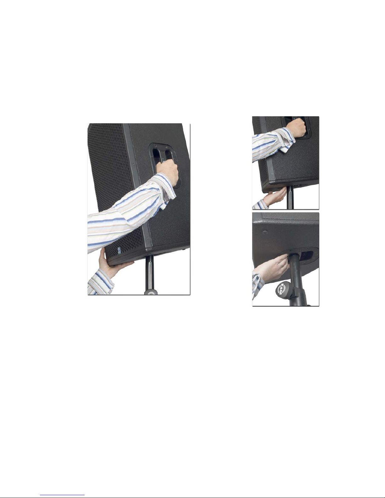
4.2.1 Handling the tiltable flange
Caution! Wrong handling may result in contusion of your fingers. Please observe the following
advice.
Slightly raise the speaker as shown in Illustration 4.1, this will enable you to align the angle.
Take care: if lifted to high, the speaker will be taken out of the flange and thus be loosened!
After lowering the speaker down ensure the flange locks in place. The angle is adjustable to + / 20 degrees in 4°- steps.
10
correct wrong
Illustration 4.1: Speaker stand insertion
Page 11
4.2.2 Button Lock
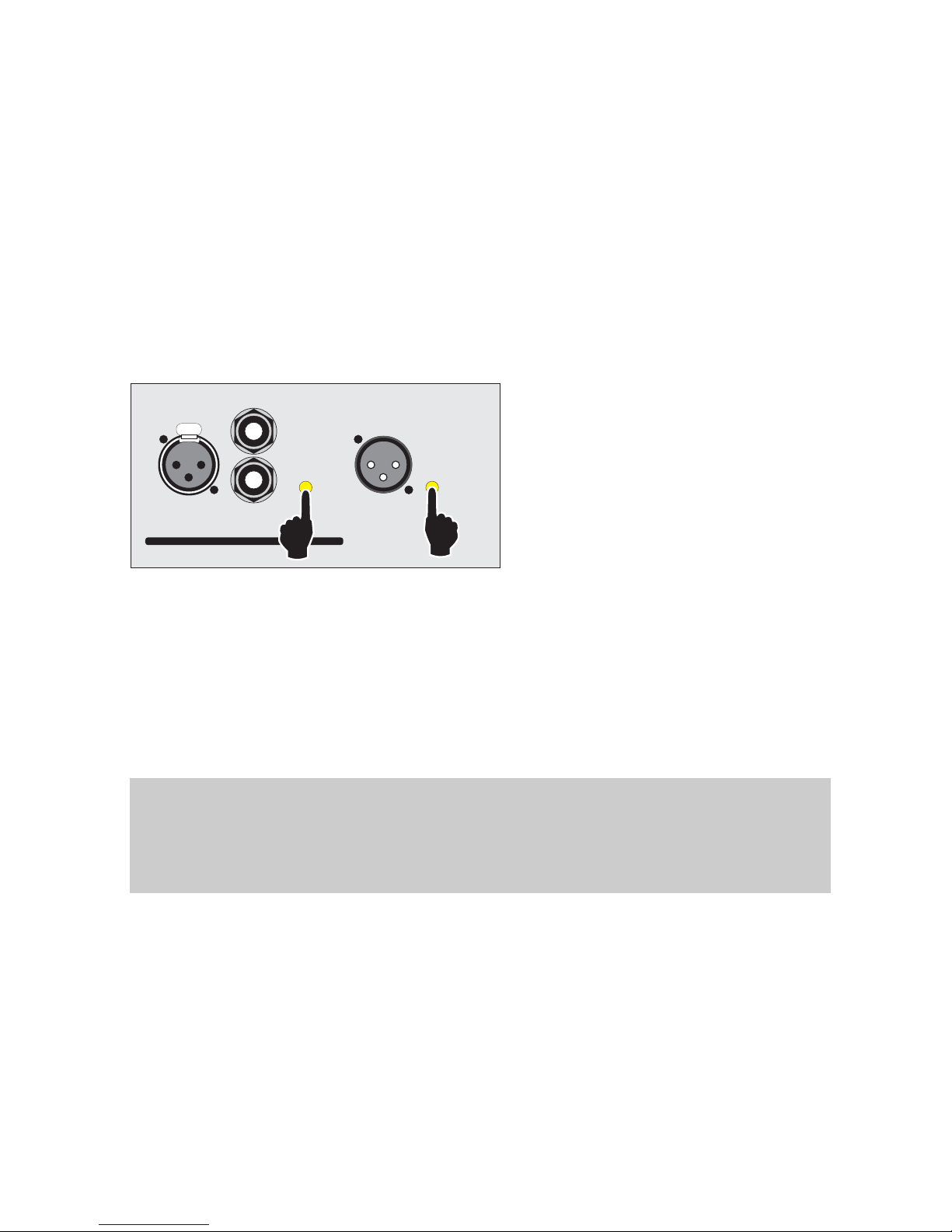
All mode buttons (labeled (2), (5), (8) in Illustration 2.2) can be locked to prevent undesired operation. To enable or disable the lock hold buttons (5) and (8) pressed until Channel 1 mode button
will light up again. By flashing following status information is displayed:
•
Locked
all buttons will flash red
•
Unlocking
all buttons will flash green
4.2.3 Automatic operating state storage
The VL3x0 will store the currently set input modes and the playback position of the USB Player
which makes setting these modes again after a power on / off cycle or power loss superfluous.
11
L Precaution is demanded in case of enabled Phantom Power!
As the Phantom Power state is also affected by the operating state storage, you should always
ensure - before switching on - there is no equipment connected to Channel 1 XLR that might be
damaged by applying Phantom Power! Please consult the manufacturers documentation as to
whether your equipment will tolerate Phantom Power.
Illustration 4.2: Locking / unlocking the buttons
CHANNEL 2 LINE OUT
SPLIT L/R
-
INSTRUMENT/LINE
I
I
CONNECTION HELP
II
II
III
III
MIC
LINE
MIC/LINE
a
rr
MIC
A-GIT
E-GIT
LINE / OTHER
-
G
Y
R
:
:
:
::
G
Y
R
:
:
:
LINKCH1
LINKCH1+CH2
MASTER POST
Page 12

4.2.4 Avoidance of Ground-Loops
If for instance two audio components bearing a different grounding potential are connected, lowfrequency interference currents may superimpose a voltage drop on the audio signal. These differing ground potentials may stem from the individual earthing of each component. The interference signal will appear with the magnitude of the difference between the grounding potentials.
While its typical frequency is located at the mains power frequency of 50 Hz the interference can
particularly occur in conjunction with the use of unbalanced input connections (such as Keyboard
6.3mm output jacks). Here, the interference signal is amplified together with the audio signal resulting in disturbing audible hum. In general, balanced inputs have the ability to suppress interference signals to a reasonable degree.
As a remedy, the ground-free switch (11) isolates the inputs grounding from chassis ground to
avoid ground loops.
If this measure should not bring relief it is advisable to insert DI-Boxes before the Inputs. In this
manner balanced interference signals should be cancelled to a reasonable extent.
4.2.5 Peak / limit indicator
The peak / limit indicator (labeled (26), located beneath the master volume control) displays the
status of the integrated protection circuits. The operating status is indicated by these displayed
colors:
Peak / Limit Indicator Status
green normal operation
orange channel or / and amplifier peak exceeded
red over temperature / protection
Status information meanings
•
Channel or / and amplifier peak (state indication: orange)
If orange color is displayed nearly constantly reduce the signal level or the volume settings
respectively. By this you prevent distorted amplification that may (under extreme circumstances)
cause damage to the unit. For loudspeaker protection the internal limiter will reduce the signal
level if the peak value is exceeded.
•
Over temperature / protection (state indication: red)
Being too strong driven the unit will mute the amplifier outputs until the power section (supply and
amplifier) have sufficiently cooled down to allow operation. Then, normal operation is resumed
automatically.
12
Page 13
4.3 Connecting sources and setting the input sensitivity
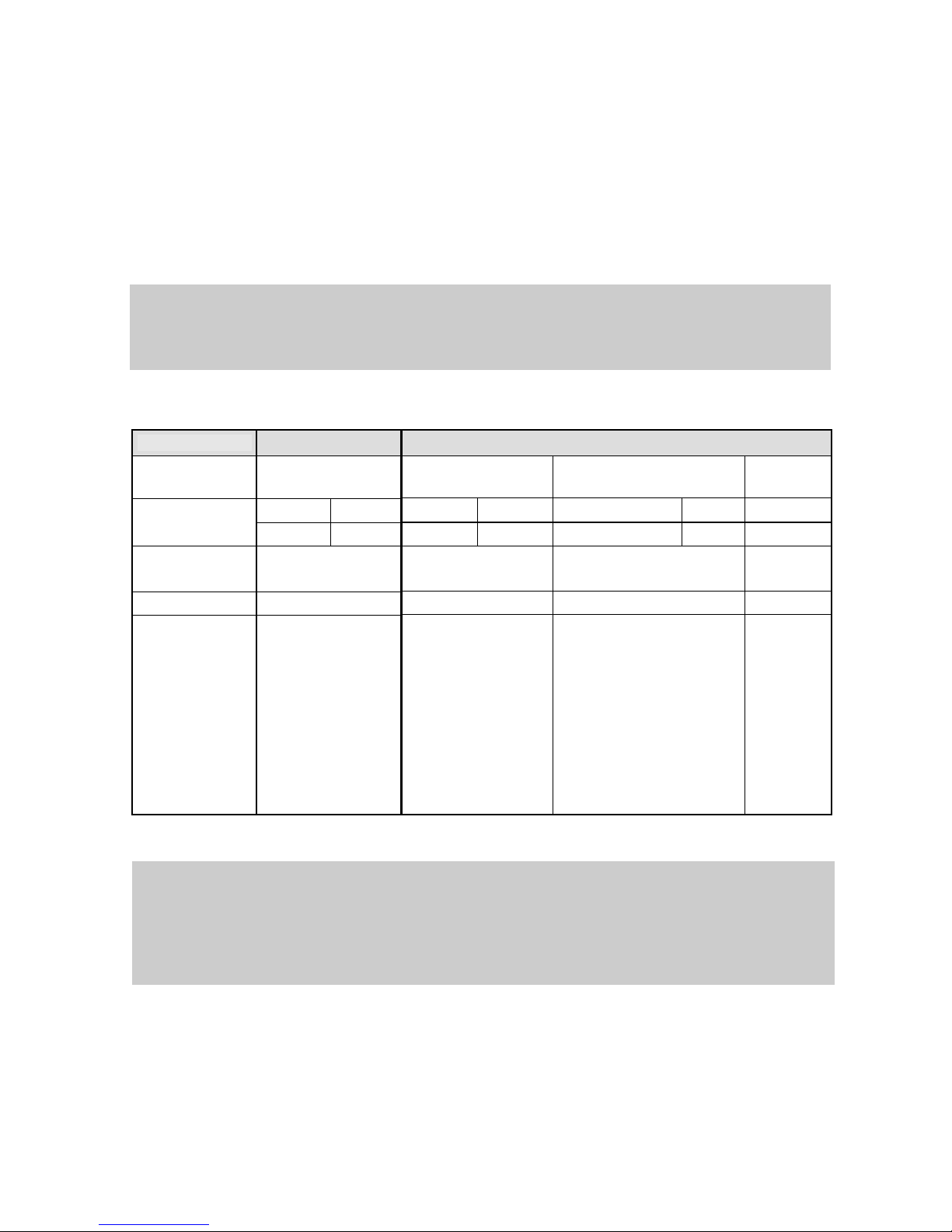
The VL3x0 features universally usable inputs. Depending on the intended application, e.g. microphones or Keyboards the individual channel sensitivity is set by the illuminated mode buttons (2)
and (5) (→ see Illustration 2.2). At the same time this setting also tailors the sound control impact
to the connected source (e.g. tone controls adapted for Acoustic Guitar or Electric Guitar).
Additionally, Channel 1 can provide Phantom Power (P48).
For application possibilities and properties of the inputs consider the following table:
Channel 1Channel 2
Input connector
XLR XLR I 6,3mm jack II 6,3mm
jack III
Maximum gain of
selected mode
MIC LINE MIC LINE INSTRUMENT LINE LINE
50 10 20 10 30 10 10
Input impedance
~ 5,6 kΩ ~ 18 kΩ ~ 1 MΩ ~ 18/9 kΩ
(bal. / unbal.)
Phantom Power
yes no no no
Application Microphones (P48)
Line-Sources, such as:
- Keyboards
- CD-Players
- Mixer outputs
Microphones
Line-Sources, such as:
- Keyboards
- CD-Players
- Mixer outputs
Instruments, e.g.
- Acoustic and Electric-Guitar
- Accordion
- Keyboard
- other instruments bearing a
pickup
Line-Sources, such as:
- Keyboards
- CD-Players
- Mixer outputs
Microphones
Line-Sources,
such as:
- Keyboards
- CD-Players
- Mixer outputs
Microphones
13
L Operating state storage
the last set input modes are being stored. Concerning the 6,3mm jacks of Channel 2 this means
in particular that each connection configuration is stored. For example, if a guitar was connected
to jack II and mode “A-GUIT” was set, this setting will be restored as soon as you connect a guitar
to jack II again.
L Tone control properties
Details on the different tone control modes are described in chapter 4.6, page 18 ff.
Page 14

Connection possibilities and input modes
This section explains the modes and properties of the individual channels.
Channel 1
•
Mode „MIC“
→ Suitable for microphones and low level sources
This mode offers a maximum gain of 50 dB which can be set via the channel volume control.
•
Mode „P48“ (Phantom Power)
→ For use with microphones and components that require Phantom Power, e. g.
condenser microphones and active DI-Boxes.
Similarly, the maximum gain is 50 dB.
•
To switch on P48: Hold down the mode button (2) of channel 1 until it lights up red.
•
To switch off P48: repeat the last described action.
•
Mode „LINE“
→ Suitable for Line sources
This will set the input sensitivity to the typical line-level of 0 dBu (0,775V
rms
respectively). Max-
imum possible gain is 10 dB.
14
L
Phantom Power
To avoid unintended activation of the phantom supply it can only be enabled and disabled by long
button press.
Page 15

Channel 2 – Instrument / Line / Mic
Though Channel 2 offers universally usable inputs its key function is instrument and line-level
amplification. For this purpose it is equipped with two 6,3mm jacks. As the gain of XLR I ranges
up to 20 dB the amplification of most standard microphones is also feasible.
As a guideline the possible input connections with their corresponding modes are listed on the
input panel:
The 6,3mm jacks II and III accommodate a variety of functions:
•
The summation of unbalanced stereo signals such as Keyboard outputs. For this purpose,
connect left and right channel to one 6,3mm jack each. The combined connection of both
6,3mm jacks is automatically detected as a line level signal input.
•
The amplification of mono signals with Line-level. Here, jack III should be used.
•
High-Z sources such as Guitars equipped with passive pick-up electronics can be connected
to jack II.
This high impedance input is especially suitable for this purpose since it will preserve the signal integrity. If High-Z pick-ups are shown low impedances they may suffer from high cut and
general level attenuation. This input will preserve the tonal characteristics of your instrument.
•
Mode „INSTRUMENT A-GUIT“ / „INSTRUMENT E-GUIT“
→ For use with electric or acoustic guitars with jack II
Applying this mode will adapt the input sensitivity and tone control characteristics to the needs of
guitars.
15
L Simultaneous connection of both XLR and 6,3mm jacks is not beneficial
Since all inputs of channel 2 are affected by the same volume control you should either use the
XLR or 6,3mm jack exclusively.
Illustration 4.3: Connection guidelines
CHANNEL 2
I
CONNECTION HELP
II III
MIC
LINE
LINE
STEREO IN (KEYB)
INSTRUMENT (A-GUIT / E-GUIT / OTHER)
a
rr
a
rr
a
rr
a
rr
aa
r
Page 16

•
Mode „LINE / OTHER“:
→ this mode enables line level sources to be amplified via
•
jack II with a maximum gain of 30 dB
•
jack III with a maximum gain of 10 dB
•
XLR I with a maximum gain of 10 dB.
If both jack II and III are connected their sensitivity will be automatically set to line-level providing
10 dB gain.
•
Mode „MIC“
Suitable for microphones using XLR I. If only one microphone is in operation we recommend the
connection to Channel 1 since it offers more gain and P48 if desired.
4.4
16
Page 17

4.5 Setting channel and master volume
Advice on setting the channel volume
Depending on which mode is set (LINE, INSTRUMENT, MIC) the channel will have a adapted
control range. Following illustration clarifies the specific operation:
17
Illustration 4.4 Different control ranges of the
channel volume
VOL
-
¥
.
.
.
0
d
B
0
d
B
.
.
.
2
0
d
B
0dB
VOL
-
¥
.
.
.
1
0
d
B
1
0
d
B
.
.
.
5
0
d
B
10 dB
VOL
-
¥
.
.
.
6
d
B
6
d
B
.
.
.
3
0
d
B
6dB
LINE Mode
INSTRUMENT
Mode
MIC / P48 Mode
Page 18
Setting the master volume
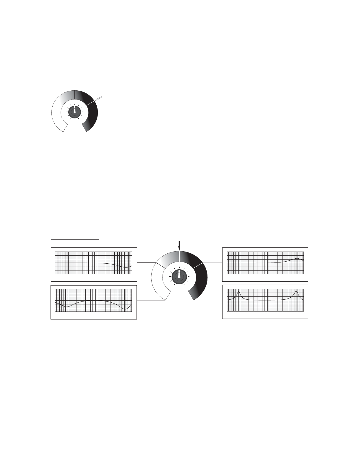
The master volume's control range covers - ∞ to 0 dB, whereas in 14 O' Clock position about -3
dB gain will be reached.
4.6 Tone Control Operation
5 USB player tone control
As usual for many 1-knob tone controls the USB player features shelving characteristics. Illustration 4.6 exhibits this behaviour.
5.0.1 Adaptive tone control of Channel 1 and 2
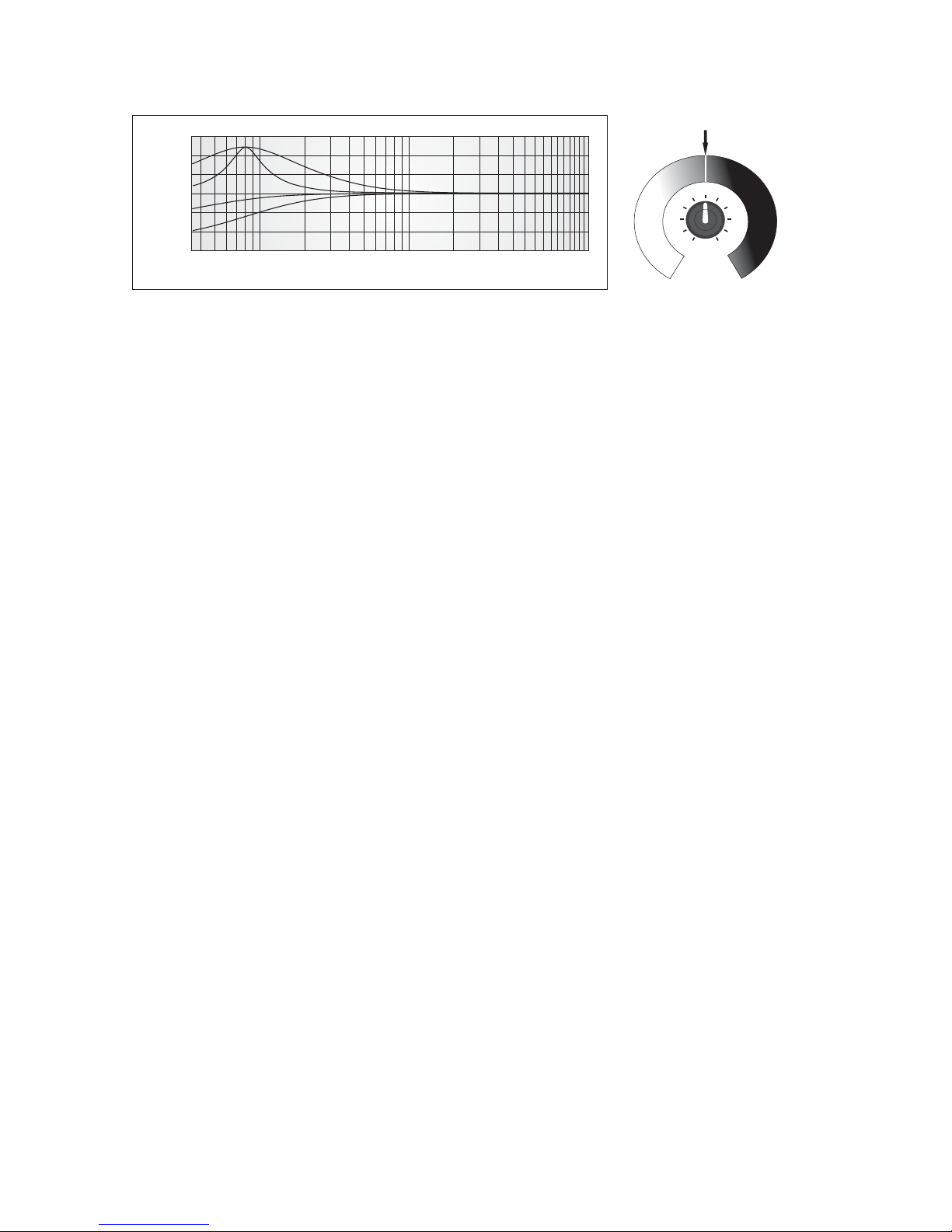
The key function of the adaptive tone control is its ability to show specialised control characteristics tailored to the requirements of different signal sources. For effective control an instrument
demands for different center frequencies for equalisation than a line source. To meet these individual needs the adaptive tone control will alter the boost and cut frequencies and also set an
appropriate gain margin (range: + / - 15 dB max.). This mode of operation very much resembles a
parametric equaliser, whereas here several parameters are altered simultaneously (center frequency, Q, gain). Illustration 4.7 portrays this principle:
18
Illustration 4.5: Master
Volume control range
VOL
-
¥
.
.
.
.
.
.
0
d
B
-
3d
B
Illustration 4.6: Frequency response curves for several control positions
USB Tone Control
SOUND
linear
LOW MID HIGH
LOW MID HIGH
LOW MID HIGH
LOW MID HIGH
Page 19
Description of the individual modes
•
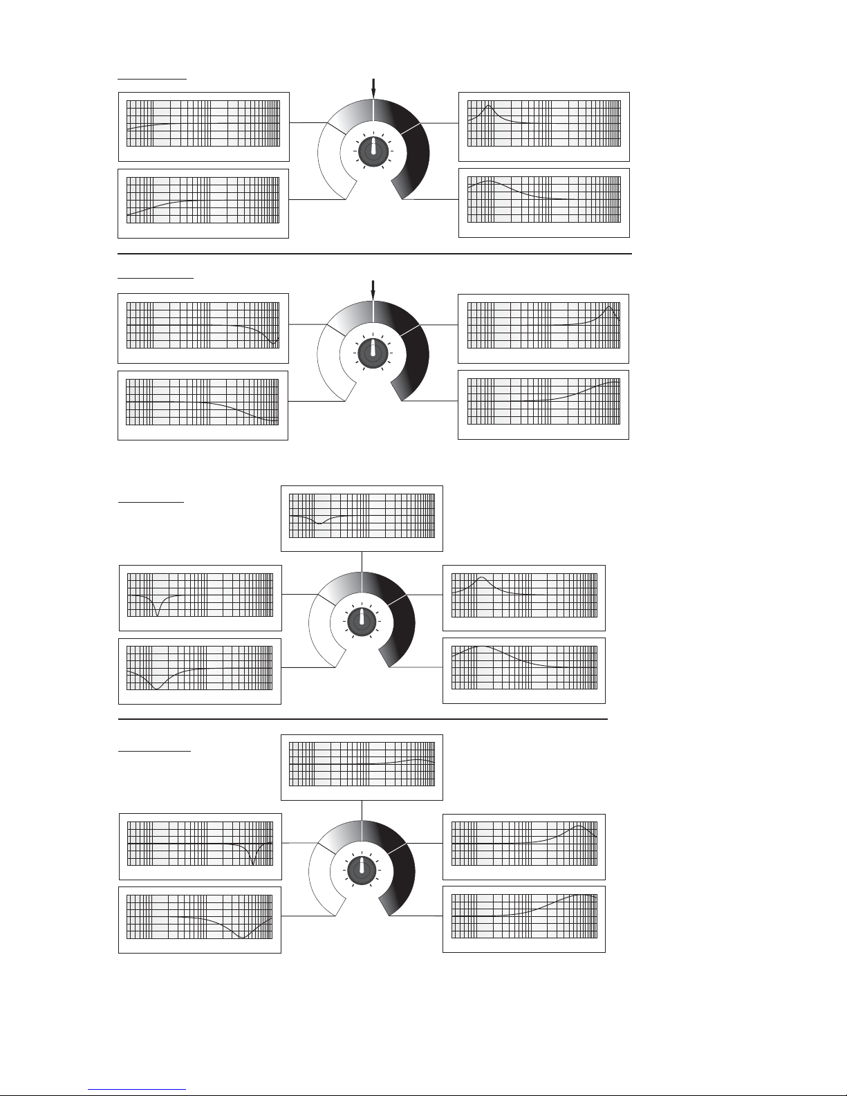
Modes „LINE“ / „MIC“ / „OTHER“
These modes incorporate a shelving tone control. In both rightmost and leftmost position the
width of the boost / cut is increased to its maximum (see illustration 4.8).
•
Mode „INSTRUMENT, A-GUIT“
This mode sets the input sensitivity and tone control characteristics to fit acoustic guitars. It will
affect the bass fundamentals between 100 and 200 Hz and the highs at 8 kHz. Turning the controls towards their right / left stop will broaden the cut / boost effect (see illustration 4.9).
•
Mode „INSTRUMENT, E-GUIT“
To adapt for electric guitars the bass is shaped at 120 Hz while the mid high center frequency will
be shifted in the region of 5-7 kHz. This takes into account for the distinctive midrange of electric
guitars. Similar to other modes, in the leftmost and rightmost positions the cut or boost is
broadened successively (see illustration 4.10).
19
Illustration 4.7: Princi ple of the adaptive tone control
LO
linear
LOW MID HIGH
0
1
2
3
Reglerstellung
0
1
2
3
Page 20
20
Illustration 4.9: Frequency response curves in "A-GUIT" mode
LO
linear
LOW MID HIGH
LOW MID HIGH
LOW MID HIGH
LOW MID HIGH
Bass Control
HI
linear
LOW MID HIGH
LOW MID HIGH
LOW MID HIGH
LOW MID HIGH
Treble Control
Illustration 4.10: Frequency response curves in "E-GUIT" mode
LO
LOW MID HIGH
LOW MID HIGH
LOW MID HIGH
LOW MID HIGH
Bass Control
LOW MID HIGH
LO
LOW MID HIGH
LOW MID HIGH
LOW MID HIGH
LOW MID HIGH
Treble Control
LOW MID HIGH
Illustration 4.8: Frequency response curves in "A-GUIT" mode
HI
linear
LOW MID HIGH
LOW MID HIGH
LOW MID HIGH
LOW MID HIGH
LO
linear
LOW MID HIGH
LOW MID HIGH
LOW MID HIGH
LOW MID HIGH
Bass Control
Treble Control
Page 21
5.0.2 Advanced tone control matr ix di spla y
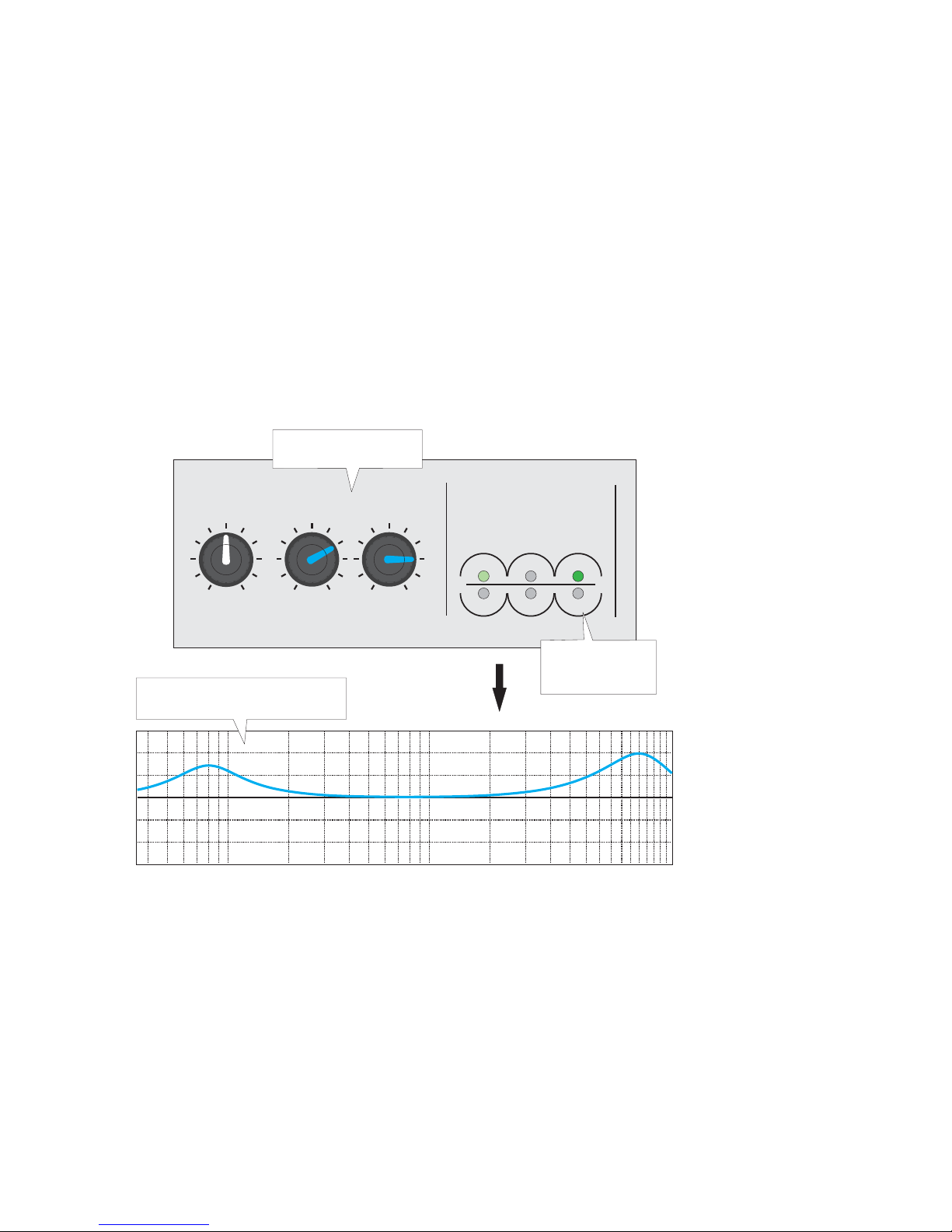
It is the task of the matrix display to show the frequency area affected by the tone control that is
currently being altered. In this manner you may visibly estimate the acoustical impact of the current setting. While the upper row stands for boost in the designated frequency regions, the lower
row symbolizes a cut. The entire frequency range is divided into three regions representing the
low, mid and high frequency band. The brightness of each LED corresponds to the boost or cut
gain.
Example
To exemplify the functioning of the LED matrix display the illustration 4.11 shows how the tone
controls position is in conjunction with the actual frequency response and the displayed LED
brightness.
21
Illustration 4.11: Conjunction of frequency response and LED matrix display
VOL LO
HI
LO MID
FREQUENCY
HI
INSTRUMENT/LINE/MIC
CHANNEL 2
ADVANCED
SOUND CONTROL
50Hz 100Hz 200Hz 300Hz 500Hz 1kHz 2kHz 3kHz 5kHz 10kHz
0dB
+12dB
-12dB
Control position
LED matrix
display
frequency response
Page 22
5.1 USB audio playback
5.1.1 Controls
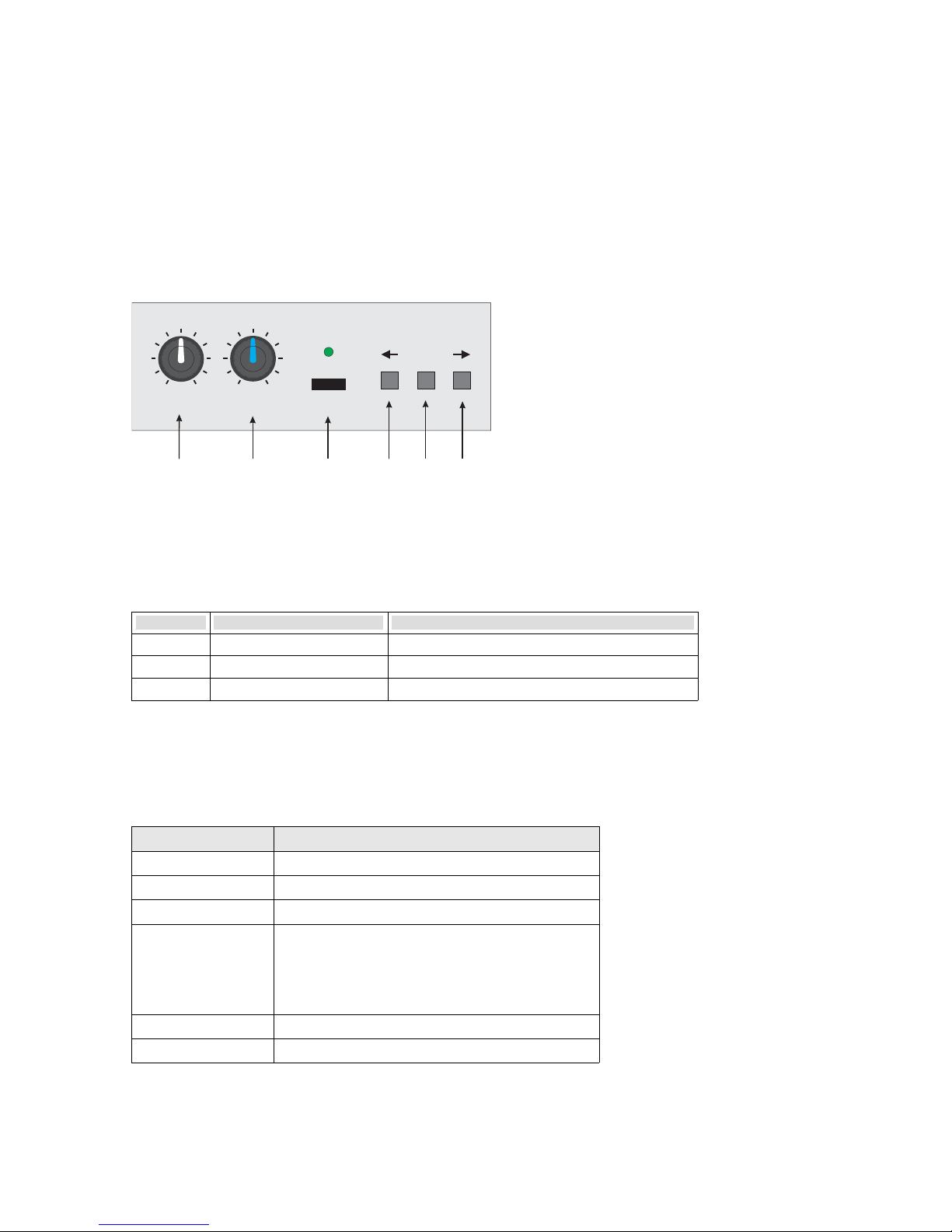
As shown on the front panel the buttons (15), (16) and (17) (located to the right of the USB
socket) are available to control the operation of the USB player (see illustration 4.12).
Additionally to the standard control set (previous, play / pause, next) the directory change is
triggered by a long press:
Button Short press Long press
play / pause
start / pause the playback reset playback position: jump to root directory
previous ←
jump to previous track jump into previous folder
next →
jump to next track jump into next folder
5.1.2 USB-LED status information
The USB LED (14) indicates these operating states:
USB LED (14) Status information
off no USB media connected
continuous green USB media detected
flashing green audio is being played
continuous red Fault, either:
•
USB device is not supported or
•
Over current: the USB device exceeds
the permitted current draw of 500 mA
continuous orange fault: no audio material found
flashing orange search in progress
22
Illustration 4.12: USB player controls
VOL USB
PLAY/ II
SOUND
12.
13.
14.
15.
16.
17.
Page 23

5.1.3 Supported audio file formats
The USB player supports the playback of MP3 and Wave files with the following requirements:
Format Bit rate Format code Sample rate
MP3 all -
up to 96 kHz
WAV
8 bit PCM / µ-law, A-law
16 bit linear PCM
24 bit linear PCM
32 bit IEEE Float
5.1.4 Playing audio files
After plugging in an USB stick the USB status LED should light up green indicating the presence
of playable audio material. You may start the playback by pressing “play” (16). This will trigger the
search of the first track.
In general,
•
folders and files are played in alphabetical order
•
folders without valid audio material are ignored
•
Invalid playlist items are skipped
To sort out the first track the USB player will firstly examine the root directory for audio and subsequently jump into the alphabetically first folder and find the first track there as well. The search
progress will go forth in this manner, including all sub folders. The later section will describe this in
detail.
5.1.5 Playback order
A reasonable playback order is kept by the alphabetical sorting of the file names and folder
names. As with the alphanumerical sorting that, by its name, relates to characters and numbers
the sorting priority is in the order:
punctuation characters – numbers – letters – remaining symbols.
Commonly, the order of audio albums is defined by title numeration, e.g. in the form:
01 – Title.mp3
02 – Title.mp3
03 – Title.mp3
23
L
Supported file systems
The file system of the USB Mass Storage Device must be either FAT12, FAT16 or FAT32.
Page 24
or also
Artist – Album – 01 Title.mp3
Artist – Album – 02 Title.mp3
Artist – Album – 02 Title.mp3
The last ordering shows that the number defining the order not necessarily needs to be in first
position. In this case the first occurring difference in the character string is crucial. This principle
also applies to folder names.
With the previously described method you may as well keep order without using playlists.
5.1.6 Folder change
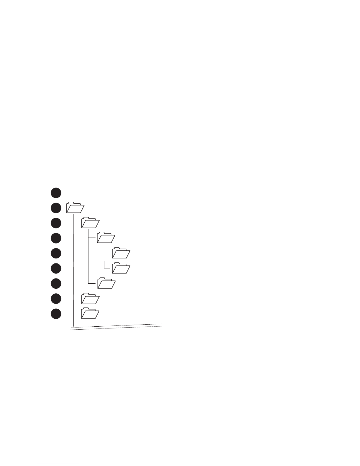
Folder navigation is controlled by a long press on either the “next” (17) or the previous “button”
(15). The illustration below clarifies this function. Here, the playback order is identified by the numbers to the left. Following the root directory as the starting position, the next folder is entered aft
all files in the root directory have been played.
24
Illustration 4.13: Folder change example
Various Artists
Favorites
Blues Power
Mix
Zest for Action
Album 01
Album 02
Music
etc.
1
2
4
5
6
7
8
9
3
[Root Directory]
Page 25
5.1.7 Usage of playlists
Playlists have the form of text files and define the playing order with line-by-line file names with or
without path destination. The format “.m3u” and “.pls” is supported.
If provided a playlist in the current playing folder the USB player will exclusively access its playlist
items, thus remaining files in this folder and its sub folders are skipped.
Example
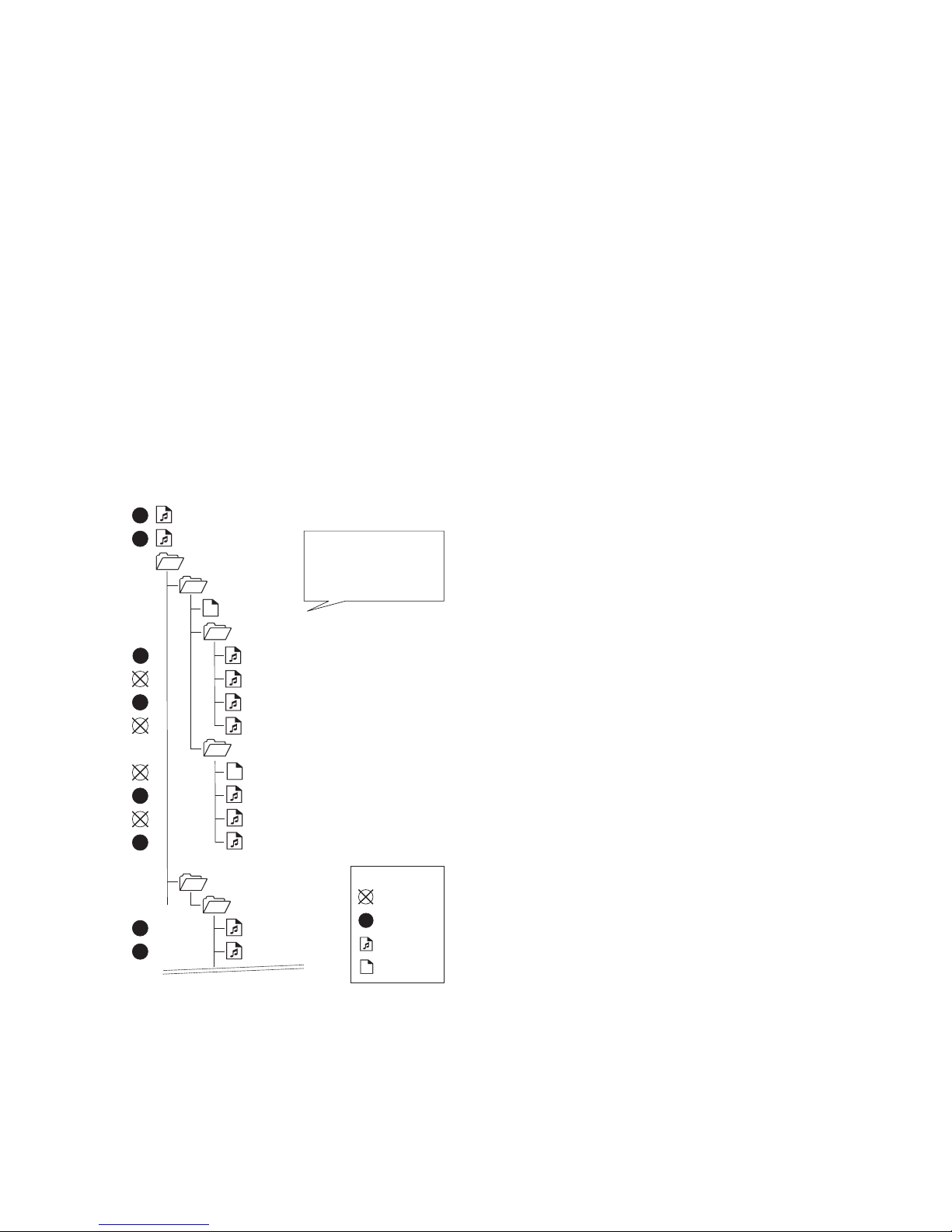
In the following example (illustration 4.14) a playback order is shown based on playlists present in
folders and sub folders. The playback starts -as usual - at top level position, which is the root directory. As mentioned before audio files get ignored if playlist is found in the current folder. This
means that as the player jumps into the folder “Favorites” it will exclusively access the playlist and
skip any remaining files and sub folders located in this current directory. Next, the player will jump
into the successive folder starting from the last valid path (here: „\Music\Favorites\“), which is the
folder “Various Artists”. If a folder change is triggered manually while a playlist is active, also the
next folder following the last accessed path will be used, this will be the folder “Various Artists”.
25
Illustration 4.14: Playback order example
Various Artists
Favorites
Blues Power
Mix
Album 01
Music
A Classic Reminiscence.wav
Mix.pls
.PLS
Selection.pls
.PLS
Cool Jazz.mp3
Track 01.mp3
Track 02.mp3
Soul Solace.mp3
Rock-Solid.mp3
Blues Power - Track 02.mp3
Blues Power - Track 03.mp3
Blues Power - Track 04.mp3
Blues Power - Track 01.mp3
Sweet Beats.mp3
etc.
Blues Power\Blues Power - Track 03.mp3
Mix\Rock-Solid.mp3
Blues Power\Blues Power - Track 01.mp3
Mix\Sweet Beats.mp3
1
2
4
5
6
7
8
3
playlist
.PLS
audio file
3
file is skipped
order number
symbols:
Page 26
5.1.8 Folder change when using playlists
If you trigger a folder change while a playlist is active the next folder starting from the path of the
playlist is being accessed. This way you may skip the remaining playlist items.
5.1.9 Creating playlists
When creating playlists please make sure the path destinations match the actual folder structure
of your USB storage device. Otherwise the playlist items will not be found.
Path destinations can be defined relative, e.g.
01 Artist - Title 05.mp3
or absolute, e.g.
Music\Favorites\01 Artist - Title 05.mp3
Should you wish to move playlists to another folder or rename folders, bear in mind that
•
if relative path definition is used, the playlist needs to be moved together with its audio files
and sub folders
•
if absolute path definition is used the playlist may be freely moved but requires leaving the
audio files at the same location.
For simplicity reasons we recommend using relative path definitions and the unified storage of
both playlist and its associated audio files.
5.2 Selecting the Line Out signal
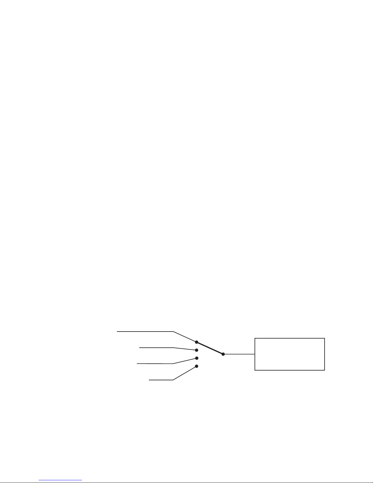
With the selectable Line Out signal you may for example easily build monitor arrangements with
multiple speaker units. In illustration 4.15 below the available signal combinations are shown.
The routing matrix offers the following signal combinations:
26
Illustration 4.15: Routing matrix
Line-Out
CH 1
CH1+CH2
SPLIT L / R
MASTER POST
green
yellow
red
off
routing selector
color indication
signal(s)
Page 27

•
LINK CH 1
Outputs the the signal of channel 1 in dependence of its channel volume (Master Pre).
•
LINK CH 1 + CH 2
Outputs the the sum of channel 1 and channel 2 in dependence of their respective channel
volume (Master Pre).
•
SPLIT L / R
Outputs the sum of channel 1, channel 2 and the right channel of the USB player. In this mode,
both the channel and master volume have effect on the output signal level.
This mode enables the use of two speaker units to play USB audio in stereo channel configuration. The master volume for both units can be set with the unit that outputs the line signal.
•
MASTER POST
Outputs the sum of all channels including the USB player. As with the SPLIT L / R mode, the
respective channel volume and master volume controls have effect on the output signal level.
Setting up monitor systems with multiple speaker units
Follow these steps:
•
Set the mode “Link Master Post” for the VL3x0 unit that will be directly connected to your
sources. This will enable you to control the over all volume with this monitors master volume
setting.
•
Connect the line out of this unit to your second VL3x0. Set these preferences to match the
volume of both units:
- set the Channel Volume of the channel connected to the line out to middle position (12 'O
clock) and choose the mode “LINE”.
- Set the master volume to maximum (rightmost position).
•
Set the channel volumes for the unit connecting your signal sources as usual.
27
Page 28

6 Firmware update
The VL3x0 is firmware update ready. If provided, updates and instructions on the updating process can be downloaded at:
http://www.kme-sound.com
7 Safety precautions
•
Do not open the unit – danger of electric shock!
Even in powered down state lethal voltages may still be stored in the power supply for a while.
•
Any repair should be performed by trained personnel.
•
Avoid the contact with spray water and extreme humidity. Especially prevent the entrance of
water through the cooling slots.
If moved from a very humid and cool atmosphere to warm temperature surroundings we
advise to wait a reasonable amount of time before powering on the unit. In this manner,
humidity can exit. This is important since condensed humidity on the electronics may cause
malfunction or even damage when switched on under these conditions.
•
Do not cover the cooling slots in order to guarantee sufficient heat dissipation.
•
Keep the VL3x0 away from heat sources and open fire.
•
Allow a secure footing and prevent any tensile loading of the connecting cables.
•
Replace any damaged power cords
•
Never disconnect the mains grounding of the power cord – Risk of electric shock!
Ground loops should be taken care of by engaging the Ground-free switch or by employing
DI-Boxes.
28
Page 29

8 Trouble shooting
→ The input signal can hardly be heard or is distorted
•
If you fail to hear the input signal even with master and channel volume raised moderately
high the signals level may need to be increased. Also the wrong channel sensitivity may be
set. Make sure to use the modes MIC for microphones and LINE for line level sources.
→ Audible distortion appears
If amplification of your source is accompanied by strong distortion possible reasons are:
•
the input is set to microphone sensitivity (MIC mode) although you have a line level signal
present. The high gain of this mode may easily result in excessive internal levels that cause
distortion. Check your mode settings. Always check the operating status LED (26), which
should not show orange flickering (peak / limit indication).
•
Channel volume is set very high but master volume is too low. Re-adjust these settings.
•
The signal's level is too high. As mentioned before you will notice this by the orange flickering
of the operating status LED (26)
→ No audible speaker output
•
If the operating status LED (26) is continuously red this means the unit is in protection state
and therefore needs to cool down first before it is again ready for operation. Otherwise, check
your source connection and make sure the operating status LED (26) shows continuous
green.
•
Otherwise, recheck your connections and settings.
→ Constant hum is present aside the amplified signal source
Hum trouble can – among other things - be caused by:
•
cables with impaired shielding
•
very long unbalanced cables which may possibly even also be placed near interfering sources
such as lighting dimmers
•
ground-loops
•
a source of very high impedance and unfavourably low level
→ Make sure the shielding of the cables is intact and use balanced inputs whenever possible
→ USB playback is not possible
•
Firstly check that the USB LED lights up green after plugging in an USB Stick. This indicates
that the device has been detected.
However, should the USB LED
•
stay continuously red the USB device was not detected or has exceeded the current limit of
500 mA. Be sure to use either FAT32, FAT16 or FAT12 file systems.
•
Temporarily light up in orange color no valid audio files were found. Check the format requirements (see 5.1.3 Supported audio file formats, on page 23).
29
Page 30
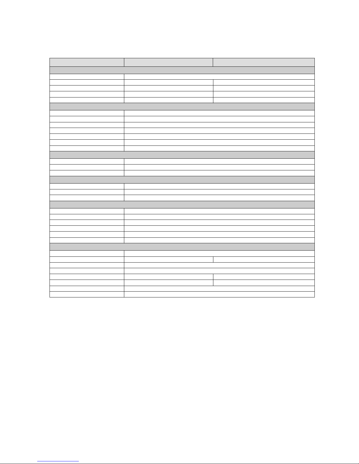
9 Specifications
30
VL 340 VL 350
Speakers
Design
8" + 1" 12" + 1"
Dispersion characteristics
85° x 55°
70 Hz - 19 kHz 60 Hz - 19 kHz
123 dB 126 dB
Features
Limiter
90 - 250 V / 50 - 60 Hz, IEC
DSP
< 1,5 ms
USB Player
FAT12, FAT16, FAT32
500 mA
Features
3
Channel 1
Channel 2
Channel 3
Outputs
Line-Out mit schaltbarer Routing-Matrix
Front grill
280 mm x 460 mm x 250 mm 390 mm x 610 mm x 360 mm
12,5 kg 21,5 kg
2 - way System, active crossover
Speaker loading
85° x 55° (rotatable horn)
Frequency response
SPL (@ RMS power)
Power amplifier
Amplifier architecture
Class D
RMS output power
350 watts (Woofer) + 150 watts (Tweeter)
Subsonic filter, digital crossovers, parametric EQs, Ground-Free switch
dynamically linked Dual-Band-Limiter (Fast Attack)
Protection circuits
Short circuit, over load, over temperature, mains voltage mismatch
Po wer cons umpti on
450 watts
Mains power input
Audio processing
32 bit, 48 MHz Clock rate, fix point processing
Latency
Sampling
24 bit
Supported media
USB Mass Storage Device (UMS)
Compatible file systems
Max. USB port output current
Number of channels
USB Player (MP3-, Wave-Format)
Mic / Line / Mic with 48Volt-Phantom power selectable
Mic / Line / Instrument / Keyboard (stereo input) selectable
Tone c ontrols
Ad vanced S ound C ontro l, a uto ma ti c a li gnment to co nnecte d source
Product Design
Mechanics
swiveling flange, max. + / - 20° alignment
Carr ying ha ndle
sideways countersunk strap handle sideways countersunk shell handle
honeycomb grill, fitted with acoustic foam
Surface protection
Black PU coating
Dimens ions (W x H x D)
Weight
Applications
floor stand monitor, PA speaker (Fullrange or Mid/High), Instrument amplifier
Accessiores
protection cover
Page 31

10 EC declaration of conformity
31
This is to certify that the following products:
Article Product Series Group
1-130-003
VL 340
PU, black 350 W + 150 W top units digital active
1-130-004
VL 350
PU, black 350 W + 150 W top units digital active
comply with the provis ions of the Directive of the Council of the European Communities
on the approximation of laws of the Member States relating to electromagnetic
compatibility (EMC Directive 89/336/EEC).
This declarat ion of conformity of the European Communities is the res ult of an
examination carried out by the Qualit y Assuranc e Department of Klingenthaler
Musikelektronik GmbH in accordance with the European Standards:
VDE 0839-6-1: 2007-10 DIN EN 610000-6-1
VDE DIN EN 610000-6-3
VDE DIN EN 610000-3-2
VDE 0838-3: 2009-06 DIN EN 610000-3-3
VDE 0860: 2011-10 DIN EN 60065
VDE 0875-103-1:2010-07 DIN EN 55103-1
VDE 0875-103-2:2010-70 DIN EN 55103-2
This declarat ion is given by
Klingenthaler Musikelektronik GmbH
Versio Series
Versio Series
0839-6-3 Berichtigung 1:2012-11
0839-2 Berichtigung 1:2011-06
Auerbacher Straße 268
D-08248 Klingenthal
abgegeben durch
Klingenthal, September 2013
Page 32
11 Warranty
Please find the warranty claims on the supplied warranty card
12 Disposal of old appliances
•
If this crossed-out wheeled bin symbol is attached to a product it
means the product is covered by the European Directive
2002/96/EC.
•
All electrical and electronic products should be disposed of a separately from the municipal waste stream via designated collection facilities appointed by the government of the local authorities.
•
The correct disposal of your old appliance will help prevent potential
negative consequences for the environment and human health.
•
For more detailed information about disposal of your old appliance,
please contact your city office, waste disposal service or shop where
you purchased the product.
WEEE-Reg.-Nr. DE 84296747
K.M.E. Klingenthaler Musikelektronik GmbH
Auerbacher Str. 268
08248 Klingenthal, Germany
Phone: +49 (0) 37467 558-0
Fax: +49 (0) 37467 558-33
E-Mail: [email protected]
Internet: www.kme-sound.com
Copyright © 2013 K.M.E. Klingenthaler Musikelektronik GmbH.
Revision: September 2013.
All rights reserved. The entire text and Image content are subject to copyright restrictions and intellectual property
protection. It may neither be copied for commercial use or transferred to third parties, nor be used in modified form.
Disclaimer: All herein mentioned brand names, product designators and their abbreviations are property of K.M.E or
their respective owner and are acknowledged as protected. Technical alterations and additions are subject to change
without notice.
32
 Loading...