

Page 1

User Manual
DAP 26
Digital Audio Processor
KME-Control
Remote Software Mainframe
Page 2

DAP 26 HW Version 1.2 r0026
DAP 26 MC Version 1.1 r0052
KME-Control Version 1.00 Build 0073
DAP 26 Plug Version 1.00 Build 0149
Manual Rev. Version 1.00 EN
Stand: 12.04.2005 [email protected]
Page 3

Functional units
The DAP 26 offers a lot of functional units for general audio processing using a
powerful DSP mainframe such as 9 filter banks with each 5 configurable filters of 9
different types, 6 crossover units with two combinable filters out of 3 types, 3 master
delays (up to 2000 ms / 685 meters), 6 channel delays (up to 500 ms / 170 meters)
and 6 dynamic processors (compressor / limiter / noise gate).
All this functional units can be programmed either directly on the hardware unit or by
using the real-time control software ‚KMEControl’..
Switches and Knobs
Front side
IN A IN B
LIMIT LIMIT LIMIT
0
+
dB
-60
CLIP
0
+
dB
-60
0
+
dB
-60
0
+
dB
-60
MUTE
dB-6 +6
MUTE
dB-6 +6
MUTE
dB-6 +6
MUTE MUTE MUTE
dB-6 +6 dB-6 +6 dB-6 +6
K.M.E. D AP26 V0.1
Preset C onfigurati on
Choose an option!
Input level meters
Two 10-digit digital level meters help to set the correct input level on the analog audio
inputs or to monitor the digital audio input level.
The graphic below shows different peak input levels on your unit:
abcd
a) too less input level
b) input level OK
c) maximum input level
d) too much input level – clipping may occur
The analog input circuit contains a limiter unit for preventing the A/D- converters from
clipping. Nevertheless the analog input level must not exceed the red LED of the
input level meter to prevent reproduction of a distorted signal. Set the source level
that only the yellow LEDs light up in peaks.
Page 4

Display
K.M.E. DAP26 V0.1
Preset Configuration
Choose an option!
A 4x20 back-lighted LCD display shows the navigation menu. You can set all
software parameters on the unit itself. Arrows in the lower right corner show the
directions to navigate to submenus. (see appendix ‘navigation structure’). Use the
navigation pad to move between the menus. Press the ‘OK’ button to select a
parameter if you are asked by the unit.
Navigation Pad
The navigation pad is to be used for accessing and changing parameters on the
display of the hardware unit. Press the OK button if you are asked by the software.
See also the appendix ‘menu structure’!
Level meter 1-6
Level correction 1-6
Mute switch 1-6
LIMIT
0
+
dB
-60
MUTE
dB-6 +6
MUTE
dB-6 +6
The level correction pot adjusts the output level of the corresponding channel by +/- 6
dB. This is done on digital signal level and independent from the gain correction in
the software plug-in.
Pressing the mute switch mutes the corresponding output channel. The level meter
still displays the output level to avoid unintentional triggering of the switches.
Page 5

There is a 10-digit LED bar-graph for each output channel which displays the
following information:
abc
a) there is an output signal on channel X (if the mute switch is not activated)
b) the signal on output X exceeds the maximum output level (if the mute switch is
not activated)
c) there is an output signal on channel X, the dynamic processor (Compressor/
Limiter) is activated and works
Mains switch
Use this switch for powering up the hardware unit. We included a power-up delay
which prevents clicks or plops in the speakers efficiently, nevertheless we
recommend switching on your power amplifiers after the DAP.
The backlighting of the display shows that the DAP is switched on and the mains
power is within the useable range. If the display does not light check your mains
voltage and / or the mains fuse which is located in the mains connector.
Page 6

Connectors
Rear side
DIGITAL OUTPUT INPUT
INPUT 6 4 2 B
INPUT
+6dB
531 AOUTPUT
DAP 26
KLINGENTHALER
MUSIKELEKTRONIK
GmbH
MADE IN GERMANY
FUSE
1 AT
85-264V ~AC;
50-60Hz
CAN 1 / RS 232
CAN 2
CAUTION!
PULL
PLUG
BEFORE
OPENING!
There are all connectors located on the rear side of the unit.
Analog inputs / level select switch
INPUT
B
INPUT
+6dB
A
The audio inputs of the DAP 26 are electronically balanced. Unless it is necessary we
do not recommend unbalanced audio connections. The inputs have to be operated
with an nominal audio level of either 775 mV (0 dB) or 1.55V (+6 dB) which you can
select using the switch beside the connector “b” corresponding to the signal level
your source units work with.
1
2
3
1
2
3
XLR-to- XLR balanced audio connection
12
3
Jack-to-XLR balanced audio connection
Use one of this cables for connecting the analog audio inputs of the DAP 26 to your
mixer / stagebox or to another signal source.
Page 7

Switching inputs to ‚analog’ (factory preset)
K.M.E. DAP26
Presetinfo
Choose an option!‹ ›
ˆ
K.M.E. DAP26
Devicesettin
g
Choose an option!‹ ›
ˆ
Devicesettings
In-select: Di
g
ital
OK: Chan
g
e Value ˆ>
K.M.E. DAP26
Preset Configuration
Choose an option! >
ˆ
Devicesettings
In-select: Analo
g
OK: Change Value ˆ>
Devicesettings
In-select: Analo
g
OK: Change Value ˆ>
ˆˆˆ
Follow this navigation scheme to activate the analog audio inputs (factory preset)
?after using the digital audio input sometimes?. This is one of the few settings that
can only be done on the hardware unit itself.
Analog outputs 1-6
OUTPUT
642531
The analog audio outputs 1-6 are electronically balanced, male XLR sockets. We do
not recommend connecting unbalanced destination devices to the DAP 26. The
nominal output level is reached if the yellow LED in the level meter lights up.
1
2
3
1
2
3
XLR-to- XLR balanced audio connection
Page 8

Computer connection,
selector RS 232 – CAN
CAN 1 / RS 232
CAN 2
• programming the unit (on PC using RS 232)
DIGITAL OUTPUT INPUT
INPUT 6 4 2 B
INPUT
+6dB
531 AOUTPUT
DAP 26
KLINGENTHALER
MUSIKELEKTRONIK
GmbH
MADE IN G ERMANY
FUSE
1 AT
85-264V~ AC;
50-60Hz
CAN 1 / RS 232
CAN 2
CAUTION!
PULL
PLUG
BEFORE
OPENING!
RS 232
COM 1
X
Connect the DAP 26 to a free COM port of your PC using the supplied RS232 cable.
You must only use the upper connector labelled ‘RS232/CAN’. Make sure that the
yellow LED beside the connector GLOWS BEFORE connecting the unit to your PC! If
the LED does NOT glow, operate the switch which is located just below this LED
using a suitable tool.
You can now run the ‘KME-Control’ software and activate the communication (see
software).
15324
7896
15324
7896
9-pole D-sub cable 1:1 as supplied with the DAP 26. The pins shown in this drawing
have to be connected, the other pins may be connected but do not affect the
communication at all.
The maximum length of such a cable MUST NOT EXCEED 5 meters or the
communication may be interfered!
Page 9

• Remote use (PC with USB- port and K.M.E. CAN- Interface)
DIGITAL OUTPUT INPUT
INPUT 6 4 2 B
INPUT
+6dB
531 AOUTPUT
DAP 26
KLINGENTHALER
MUSIKELEKTRONIK
GmbH
MADE IN G ERMANY
FUSE
1 AT
85-264V~ AC;
50-60Hz
CAN 1 / RS 232
CAN 2
CAUTION!
PULL
PLUG
BEFORE
OPENING!
USB
CAN Port
CAN Bus
1...>250 m
AFTER the installation of the KMEControl mainframe software you can connect the
USB port on your computer with the K.M.E. CANport interface using the supplied
USB cable. All necessary device drivers will be loaded automatically when
connecting the interface for the first time. Make sure that the yellow LED does not
light before connecting the CANport interface to your DAP 26 using the supplied or a
modified cable. Connect the supplied CAN terminator plug to the lower socket of your
DAP 26. If there are more DAPs daisy-chained, connect the CAN terminator plug to
the free connector of the last device in your CAN chain!
You can now run KMEControl software and activate the communication (see
software).
15324
7896
15324
7896
CAN Bus Link cable
This cable can be used connecting the DAP 26 to the CAN port interface box. Use
such cable also for linking the CAN bus from unit to unit. Do not forget connecting the
CAN terminator plug to the free connection port of the last unit, otherwise the CAN
transmission could be disturbed.
Note: By using a self-made cable make sure to connect the pins needed for CAN
transmission. They are different than in RS232 mode unless using 9 wire cable!
Page 10

This cable can be used connecting the DAP 26 to the CAN port interface box, using
your multicore system (i.e. XLR). Use such cable also for linking the CAN bus from
unit to unit. Do not forget connecting the CAN terminator plug to the free connection
port of the last unit, otherwise the CAN transmission could be disturbed.
1
2
3
15324
7896
15324
7896
1
2
3
Digital Audio Input
Digital Audio Output
DIGITAL
INPUTOUTPUT
The digital input accepts digital audio signals according to AES/EBU with a bit rate of
16 to 24 and a sampling frequency of 32 to 96 kHz using an internal format-/sample
rate converter chip. The digital audio output loops the selected input (analog/digital)
as a 24-bit/96 kHz AES/EBU signal for cascading additional units or recording the
signal to a studio digital recorder. All digital connections are transformer- balanced for
maximum protection against ground loops.
1
2
3
1
2
3
Digital Audio Connection Cable (AES/ EBU) w. 110 Ohms
We do not recommend using “normal microphone cable” for AES/EBU connections
also when it ‘seems’ to work. Only specified 110 Ohms digital audio cable will give a
proper connection without data loss and digital drop-outs.
Page 11

Switching the inputs to ‚digital’:
K.M.E. DAP26
Presetinfo
Choose an option!‹ ›
ˆ
K.M.E. DAP26
Devicesettin
g
Choose an option!‹ ›
ˆ
Devicesettings
In-select: Analo
g
OK: Change Value ˆ>
K.M.E. DAP26
Preset Configuration
Choose an option! >
ˆ
Devicesettings
In-select: Di
g
ital
OK: Chan
g
e Value ˆ>
Devicesettings
In-select: Di
g
ital
OK: Chan
g
e Value ˆ>
ˆˆˆ
Follow this navigation scheme for selecting the digital audio input of the DAP 26. This
is one of the few actions that can only be used on the hardware unit itself!
Mains power connector / fuse
DAP 26
KLINGENTHALER
MUSIKELE KTRONIK
GmbH
MADE IN GERMANY
FUSE
1 AT
85-264V~AC;
50-60Hz
CAUTION!
PULL
PLUG
BEFORE
OPENING!
Connect the supplied mains power cable to this socket. If the supplied cable is not
conform to your local mains allocation, use another cable which fits to the necessary
specification or ask a technician to change the mains plug. The DAP 26 works with all
types of mains power between 100 and 250 volts without pre-selection.
If the fuse breaks, replace it by using an 1 amp slow-blow fuse of the 5x20 shape. Do
NOT use fuses different to that type and do NOT try things like ‘patching’ the broken
fuse with aluminium foil etc. because this may lead to risk of fire or electric shock!
If the new fuse burns out again then there might be a damage inside the unit! There
are no user-serviceable parts inside the DAP 26! Contact the K.M.E. support in this
case!
Page 12

Handling
Functional units (digital)
All of this functional units are to be set directly in the hardware unit or using the
K.M.E. Control software. The names refer to the MENU PROMPT.
Input Channels
DSP- functions in the input channels
Delay
Channel [1 … 3]
Value [0 – 2.000 ms]
Time-delay in the input and all output channels routed to this input channel
(Master – Delay).
Mute
Channel [1 … 3]
Value [Mute Off … Mute On]
Mute in the input and all output channels routed to this input channel (Master –
Mute).
Gain
Channel [1 … 3]
Value [-60 dB ... +10 dB]
Gain in the input and all output channels routed to this input channel (Master –
Gain). The output level pots are to be used independently!
Filters
Channel [1 … 3]
Filter [1 ... 5]
Type [Filter type – see chapter ‚Filters’]
Frequency [20 Hz ... 44 kHz]
Q (bandwidth) [0,1 … 20]
Gain (boost/cut) [-20 dB … +12 dB]
Equalizer of the Input and all output channels routed to this input (Master –
EQ). This EQ can be used as ‘main’ equalizer for the PA system . More
information to the filters is given in the chapter ‚Filters’!
Output Channels
DSP- functions in the output channels
Delay
Channel [1 … 6]
Value [0 - 500 ms]
Time-delay in the output
Mute
Channel [1 … 6]
Value [Mute Off … Mute On]
Page 13

Mute of the output
Gain
Channel [1 … 6]
Value [-60 dB ... +10 dB]
Gain level of the output
Phase
Channel [1 … 6]
Phase [0° (In Phase) … 180° (Out of Phase)]
Polarity of the output
Filter
Channel [1 … 6]
Filter [1 ... 5]
Type [Filter type – see chapter ‚Filters’]
Frequency [20 Hz ... 44 kHz]
Q (bandwidth) [0,1 … 20]
Gain (boost/cut) [-20 dB … +12 dB]
Equalizer of the Output which can be used for correction of different speaker
output ways. More information to the filters is given in the chapter ‚Filters’!
Xover
Channel [1 … 6]
LP-Type [Bypass; Butterworth; Linkwitz- Riley; Bessel]
LP-Freq [20 Hz ... 44 kHz]
LP-Order [1 ... 8] (filter-depending)
HP-Type [Bypass; Butterworth; Linkwitz- Riley; Bessel]
HP-Freq [20 Hz ... 44 kHz]
HP-Order [1 ... 8] (filter-depending)
Frequency crossover networks for the different output channels. Using a single
filter (low-pass or high-pass) or a valid combination of both filter banks (bandpass) a powerful tool for controlling PA systems is given to the user.
The user can select a filter of the types Butterworth / Bessel and Linkwitz /
Riley. For users without profound knowledge of filter theory we recommend
using the Linkwitz- Riley filter algorithm for most applications.
Dynamic
Channel [1 … 6]
Type [Bypass; Limiter; Compressor]
Gain [-10 dB … +10 dB]
Threshold [-40 dB … +10 dB]
Knee [0 dB …10 dB]
Ratio [1:1 … 10:1] (nur Compressor)
Attack [0,1 ms … , 1000 ms]
Release [1 ms … 10000 ms]
Dynamic processor of the output.
Page 14

Depending to the setting of the parameters a dynamic processing of the input
material will occur when the audio signal level exceeds the adjusted threshold
value. The gain reduction works corresponding to the selected algorithm
(compressor or limiter). The limiter works with a ratio of infinite:1 what means
that the input level may be theoretically be increased by any value without a
change in the output level which can be specified using the threshold and gain
slider.
The knee value describes the shape of the regulation curve. A knee value of 0
means a hard compression / limiting (the processing starts immediately after
exceeding the threshold level), a higher knee value describes a curve which is
more soft and sounds normally better depending on the program material.
The attack/release time draw the speed of the gain regulation mechanism. A
longer attack time will let some signal peaks pass which may sound more
powerful, a short attack time will give more protection to the speakers.
A longer release time is advantageous for maximum protection of speaker
components, on the other hand a short release time increases the average
sound level (using the compressor algorithm).
Noisegate
Channel [1 … 6]
Type [Bypass; Gate On]
Threshold [-85 dB … -35 dB]
Close [1 ms … 1000 ms]
Hold [1ms … 10000 ms]
Noise gate of the output. Due to the setting of threshold level the noise gate
can be used for gating disturbing background noise or even audio sources of
low level. Just set the threshold to the level you want to gate – set a hold time
(the processor “waits” this time before fading out the audio signal) and a close
time (length of the fade-out itself). When the audio level is above the threshold
again, it is faded in quickly and automatically!
Page 15

Filter features
The DSP of the DAP 26 comes with many different filter types which are combinable
as desired. In the following you can find some short information about the filters and
their usage.
Context between bandwidth and the „Q“ factor
Bandwidth Q comment Q Bandwidth comment
(octaves) factor factor (octaves)
0,5 2,9 Narrow 0,4 3,0 wide
1,0 1,4 ... 1,4 1,0 ...
1,5 0,9 ... 2,4 0,6 ...
2,0 0,7 wide 4,4 0,3 narrow
Parametric filters
The so called ‚parametric’ filters are widely used in professional audio equipment, for
example in mixing desks or speaker processors. The curve of this filter is described
with certain parameters, mainly the centre frequency, the bandwidth and the gain
(boost/cut) of the filter. Combinations of these parameters can control the frequency
response of an acoustical system.
Page 16

PEQ I
Parametric Equalizer Type I
Full-parametric equalizer with different bandwidth for boost (normal) and cut (more
narrow) to create more subtle changes in the audio material. We recommend using
this filter for ‘standard’ audio requirements.
Centre frequency 20 Hz - 44 kHz
Boost/cut + 12 dB - - 20 dB
bandwidth „Q“ 0,1 - 20
It is recommended to set the value for „Q“ between 0.4 (wide) – 1.4 (normal) – 4.0
(narrow). Higher / lower “Q” values are not recommended unless the user has
enough knowledge using this special filters.
PEQ II
Parametric Equalizer Type II
Full-parametric equalizer like the types known from mixing desks.
Centre frequency 20 Hz - 44 kHz
Boost/cut + 12 dB - - 20 dB
bandwidth „Q“ 0,1 - 20
It is recommended to set the value for „Q“ between 0.4 (wide) – 1.4 (normal) – 4.0
(narrow). Higher / lower “Q” values are not recommended unless the user has
enough knowledge using this special filters.
Page 17
Shelv- filter
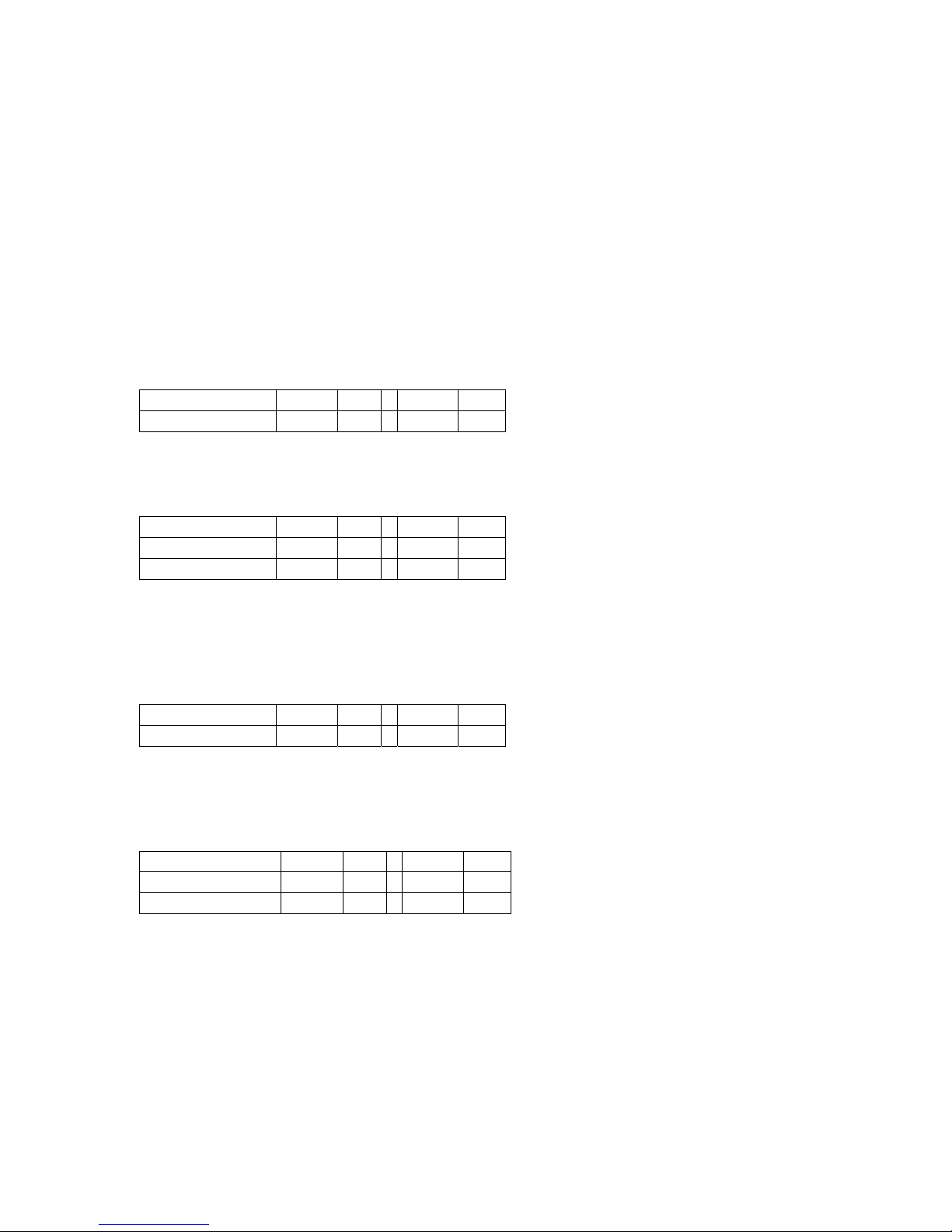
A shelv filter can be found in nearly every mixing desk, normally for low and high
frequency adjustment. They can boost or cut a wide frequency range above (high
shelv) or below (low shelf) the mid- frequency. Furthermore we added shelv filters
with adjustable bandwidth (LSQ and HSQ) which are, corresponding to the value of
the „Q“ facto (we recommend values between 0,4 and 4,0), either more “flat” than
“normal” shelvs (Q=0.7) or with a higher “Q” (1.0 to 4.0) they create an useful “peak”
around the mid frequency.
Setting the bandwidth outside of Q <0,4 und Q >4,0 is not recommended.
LS 6dB
Lo- Shelv- Filter 6 dB
mid frequency 20 Hz - 44 kHz
Boost/cut + 12 dB - - 20 dB
LSQ 12dB
Lo- Shelv- Filter 12 dB with adjustable “Q” factor
mid frequency 20 Hz - 44 kHz
Boost/cut + 12 dB - - 20 dB
bandwidth „Q“ 0,1 - 20
At Q= 0,7 you have a „normal“12dB- Shelv- Filter.
Setting the bandwidth outside of Q <0,4 und Q >4,0 is not recommended.
HS 6dB
Hi- Shelv- Filter 6 dB
mid frequency 20 Hz - 44 kHz
Boost/cut + 12 dB - - 20 dB
HSQ 12dB
Hi- Shelv- Filter 12 dB with adjustable “Q” factor
mid frequency 20 Hz - 44 kHz
Boost/cut + 12 dB - - 20 dB
bandwidth „Q“ 0,1 - 20
At Q= 0,7 you have a „normal“12dB- Shelv- Filter.
Setting the bandwidth outside of Q <0,4 und Q >4,0 is not recommended.
Page 18
High-pass and Low-pass
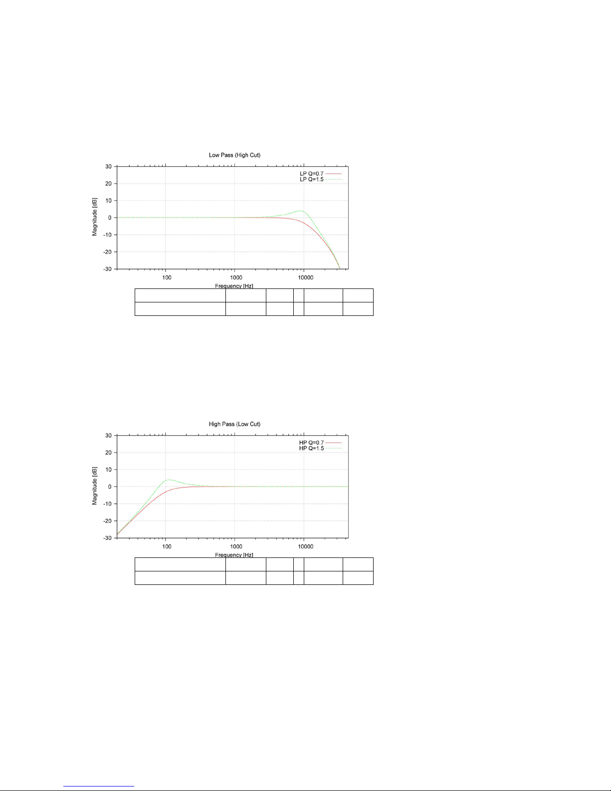
To restrict the frequency response of an acoustic system in the low or the high end,
the high pass (which actually means “low-cut”) and the low pass filter is implemented.
LP
Lowpass Filter 12 dB with adjustable “Q” factor
mid frequency 20 Hz - 44 kHz
bandwidth „Q“ 0,1 - 20
At Q= 0,7 you have a „normal“ low pass filter like you find it in some professional
mixing consoles (High-Cut).
Setting the bandwidth outside of Q <0,4 und Q >2,0 is not recommended.
HP
High Pass Filter 12 dB with adjustable “Q” factor
mid frequency 20 Hz - 44 kHz
bandwidth „Q“ 0,1 - 20
At Q= 0,7 you have a „normal“ low pass filter like you find it in some professional
mixing consoles (Lo-Cut).
Setting the bandwidth outside of Q <0,4 und Q >2,0 is not recommended.
BP
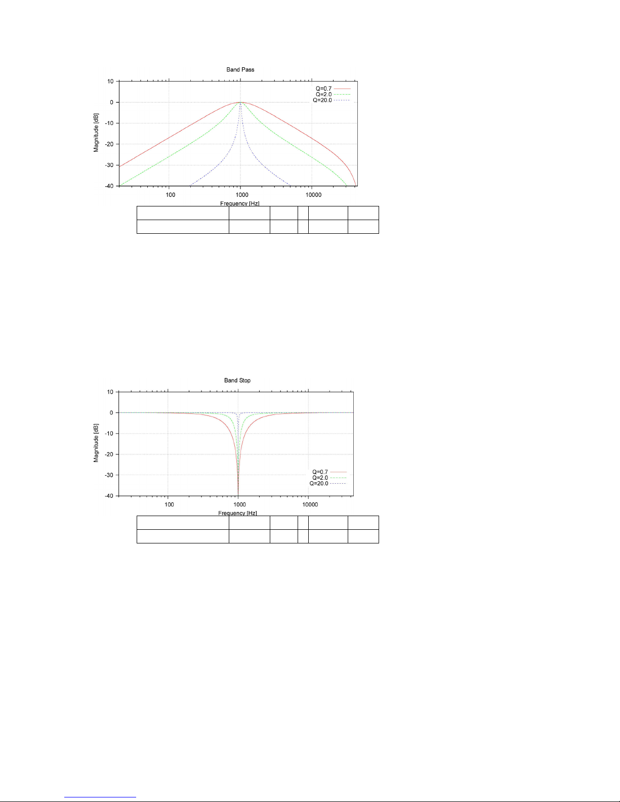
Bandpass- Filter with adjustable “Q” factor
The band-pass filter is rarely used in professional audio technology. The band-pass
filter lets, in opposite to the notch filter, pass a audio band defined by the mid
frequency and bandwidth.
Page 19
mid frequency 20 Hz - 44 kHz
bandwidth „Q“ 0,1 - 20
BS
Notch Filter
The notch filter filters out a frequency range defined by the mid frequency and the
bandwidth. With a “Q” factor above 5 this filter is very narrow, allowing the user to
filter out unwanted frequencies (i.e. mains hum at 50 Hz and certain harmonics)
completely. With a “Q” factor below 5 the filter response is quite wide but this set-up
is seldom used in professional audio systems.
mid frequency 20 Hz - 44 kHz
bandwidth „Q“ 0,1 - 20
Page 20
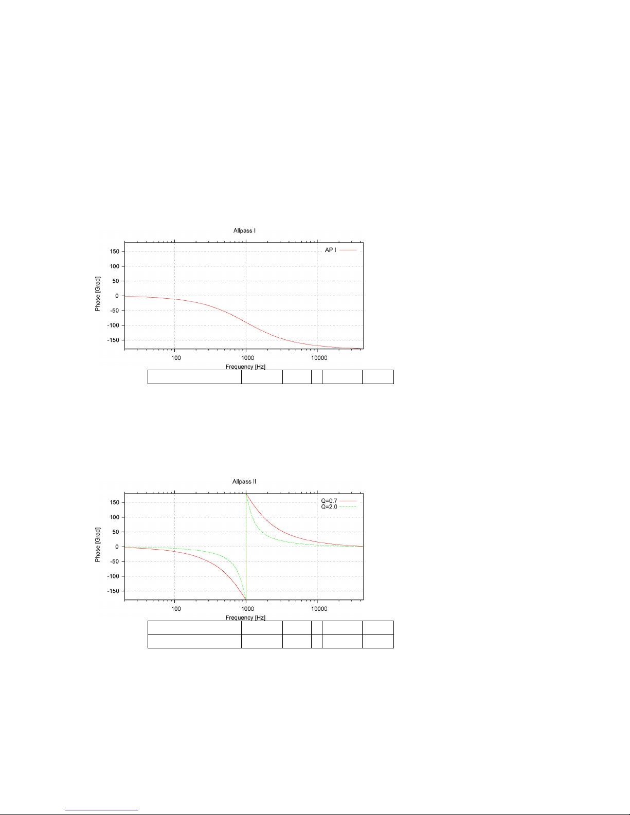
All-pass filters do not change the frequency response of an acoustoelectric system at
all but the phase response. They can be used to influence the phase response. This
is a complex field in filter theory and so all-pass filters should only be used by
engineers who have ‘enough’ theoretical background. Incorrect all-pass filtering may
not damage the sound system but affect the sound in a negative way.
The mode of action is presented here:
AP I
All-pass filter Type I
This filter creates a quite flat, smooth phase shift over the whole frequency range with
a characteristic 90° pole at the centre frequency.
mid frequency 20 Hz - 44 kHz
AP II
All-pass filter Type II
This filter creates a steep phase shift at the centre frequency. The course of the
phase curve may be affected by the „Q“ factor.
mid frequency 20 Hz - 44 kHz
bandwidth „Q“ 0,1 - 20
Page 21
The software - KME Control
KME Control is a flexible software mainframe to be completed with different plug-ins
which can control different K.M.E. products. At present there are plug-ins for the DAP
26 and the RCM Network Remote Control Module available.
Installation
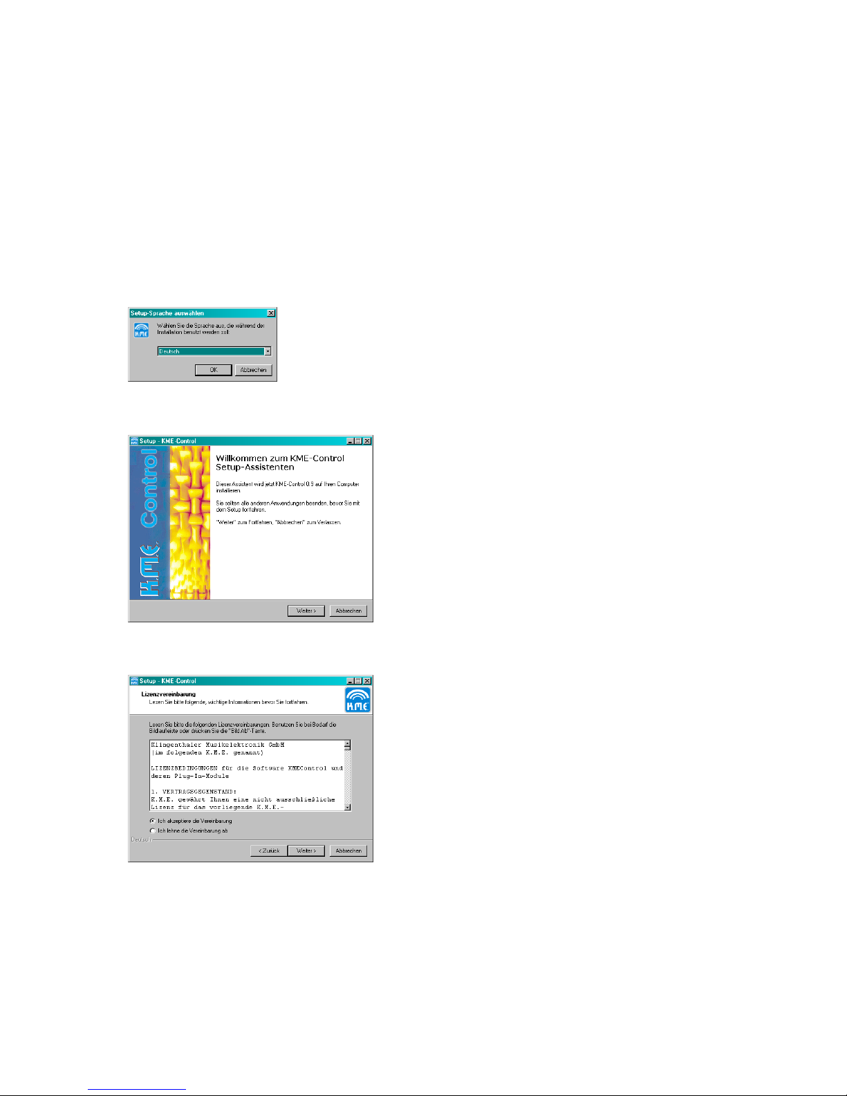
Start the program ‘KME-Setup.exe’ which you have received together with the DAP
26 (Installation CD) or from the Internet download.
Select the installation language (German/English) and press ‘OK’!
Follow the installation assistant – click ‚Continue>’.
Please accept the licence agreement and click ‚Continue>’.
Page 22
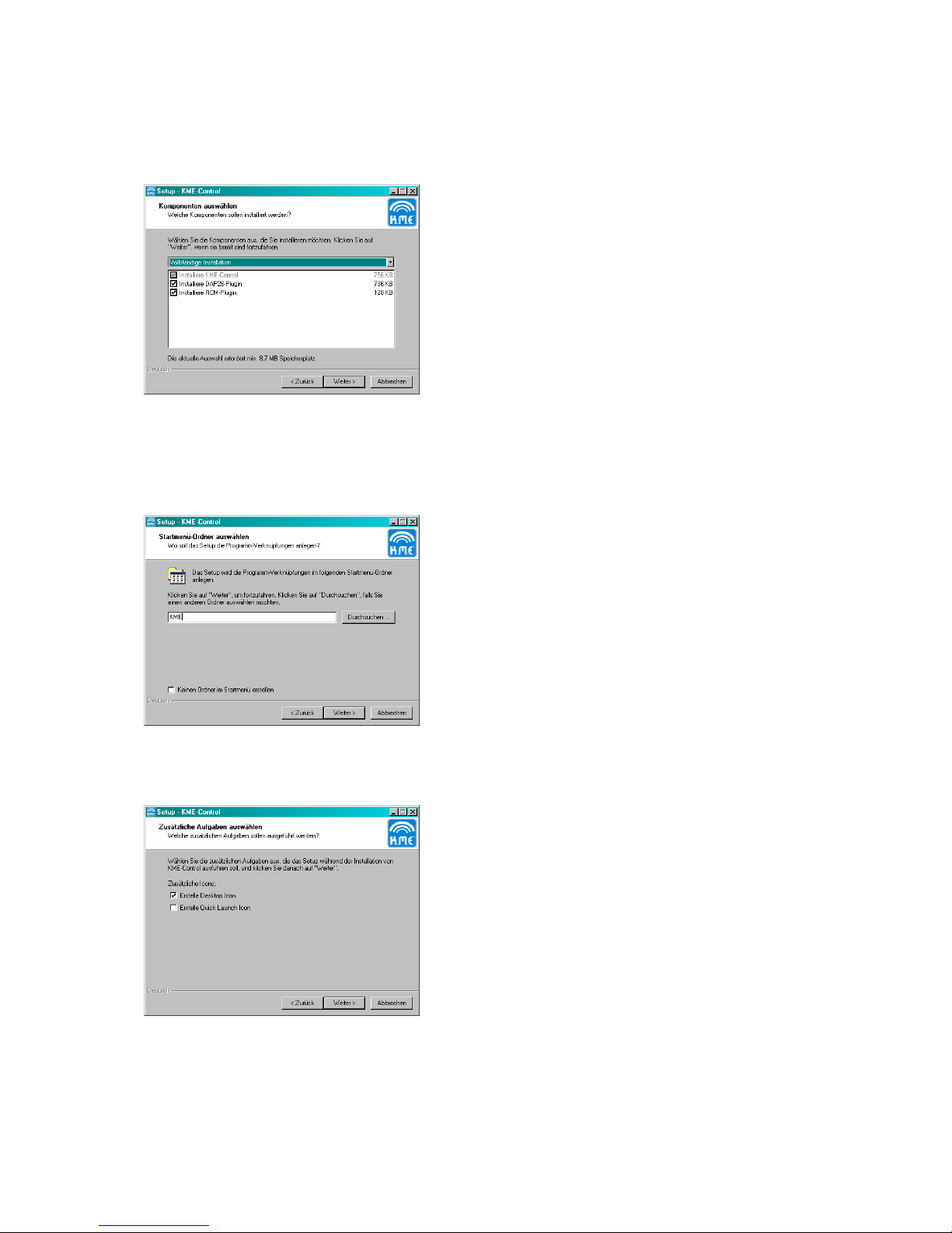
Select an installation folder in your system hard disc. We recommend using the folder
suggested by the installation assistant. Click ‘Continue>’.
Select the modules you want to install within the mainframe. The modules may vary
with different software releases. To work with the DAP 26 you must install the DAP
plug-in. You cannot deselect the installation of the mainframe KME Control.
Select the entry in your ‚Start’ Menu. We recommend accepting ‚KME’. Click
‘Continue>’.
Select if you want to create a Quick Launch icon or an icon on your desktop.
Page 23
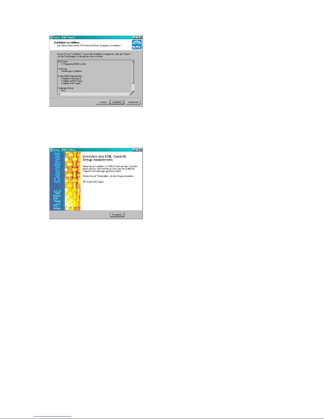
In this window you can check all installation details before you proceed. If everything
is set up right, click the ‘Installation’ Button to start the software installation on your
computer.
After the installation has finished successfully, this window is shown. You can select
if you want to start KME Control now by clicking the ‘Finish’ Button. You can also
deselect the checkbox if you want to start KME Control later.
Page 24
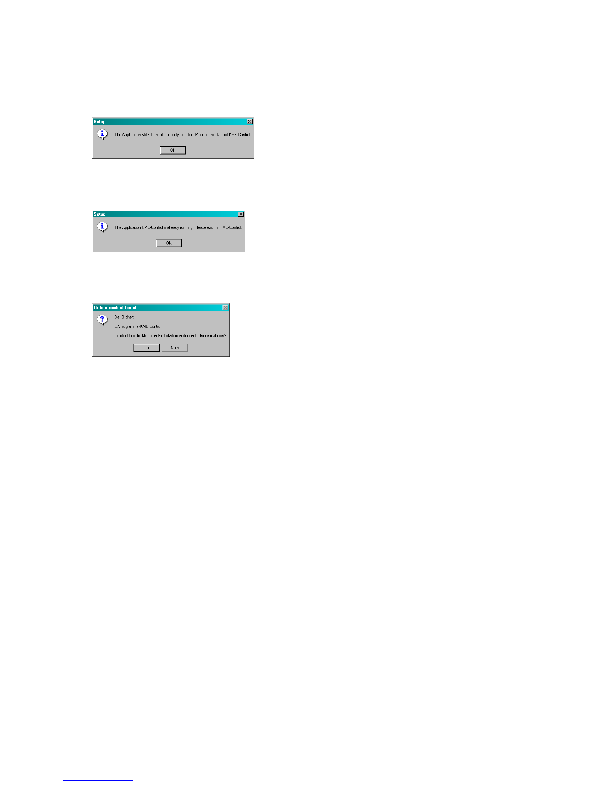
Installation Problems:
• Program cannot be installed, following window appears:
De-install an older version of KME Control first. Select ‘Start’ ‘Programs’ ‚KME’ (or
your installation folder) ‚Remove KME Control’ and follow the de-installation
assistant.
Close KME Control first before trying to install a new plug-in or update. We also
recommend closing all other programs during an installation process of new software.
If you receive this message you can select ‚Yes’ without caring about your user
presets stored in this folder to be deleted. They will not be deleted, even by deinstallation of the software. To erase the software completely from your computer,
this folder has to be deleted manually using the Explorer window. All of your user
data will be lost.
Page 25
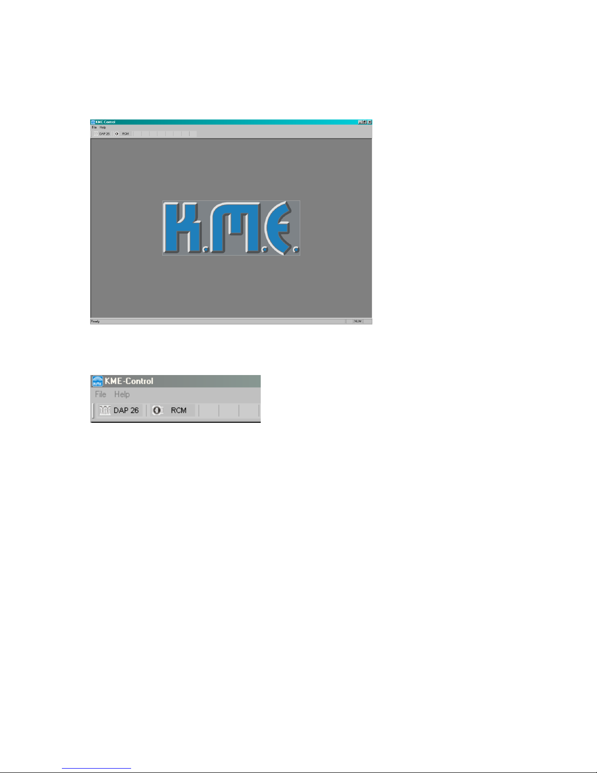
Software operation
Start KMEControl.
On the mainframe window you find the installed plug-ins in a bar below the main
menus. In this example the plug-ins DAP 26 and RCM are installed.
Clicking on the DAP 26 symbol the plug-in will be loaded into the mainframe window.
The plug-in may be activated more than once, in the actual release you can select up
to four active windows (limited to screen capabilities).
In RS 232 mode you can connect up to four DAP units to your computer (if enough
COM ports are present).
By adding the CAN Bus option the user is able to use up to 63 hardware units on one
host computer. Refer to the CAN Bus part of this manual for additional information.
The mainframe window with loaded DAP 26 plug-in:
Page 26
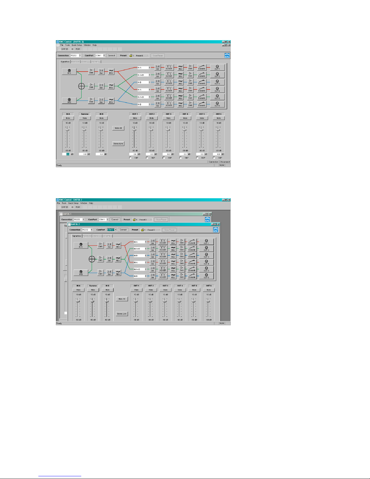
Example: Connecting two DAP 26 on different COM ports:
Page 27
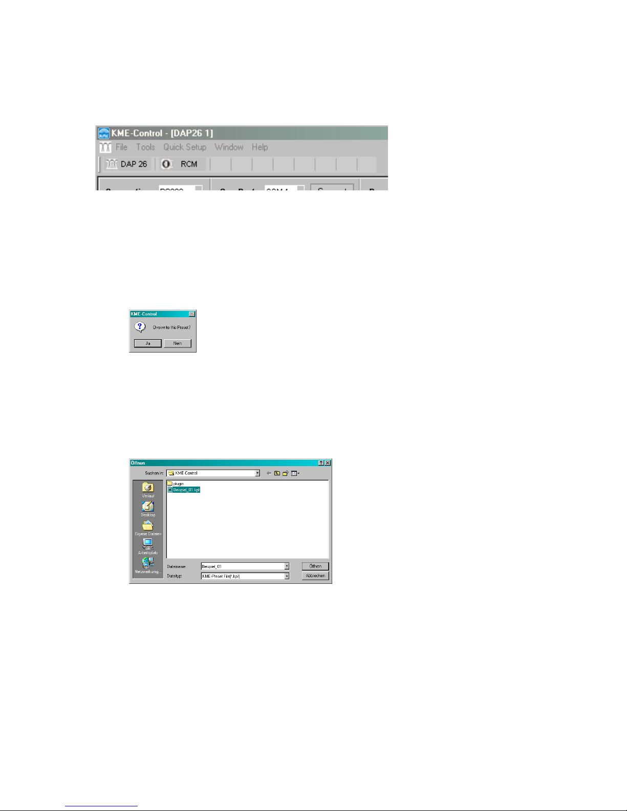
Functions in the main Window
Menu bar:
File
Open Preset
Opens a preset from a local drive of your computer. You are being asked if you want
to overwrite the actual (which means the preset inside the active window) preset. If
you are not sure that you want to discard your last changes, select ‘No’ and save
your preset to disc using ‘Save Preset’.
If you choose ‚Yes’ the ‚Open’ dialogue window will be opened. Navigate to the
location of the preset file you want to load and click ‘Open’. The only files to be
loaded are *.KPF which means K.M.E. preset file.
Select the preset you want to load and click ‚Open’.
Save Preset
Saves your actual preset to a disc of your computer. You can send this preset file to
the technical support later or archive it for future use.
Page 28
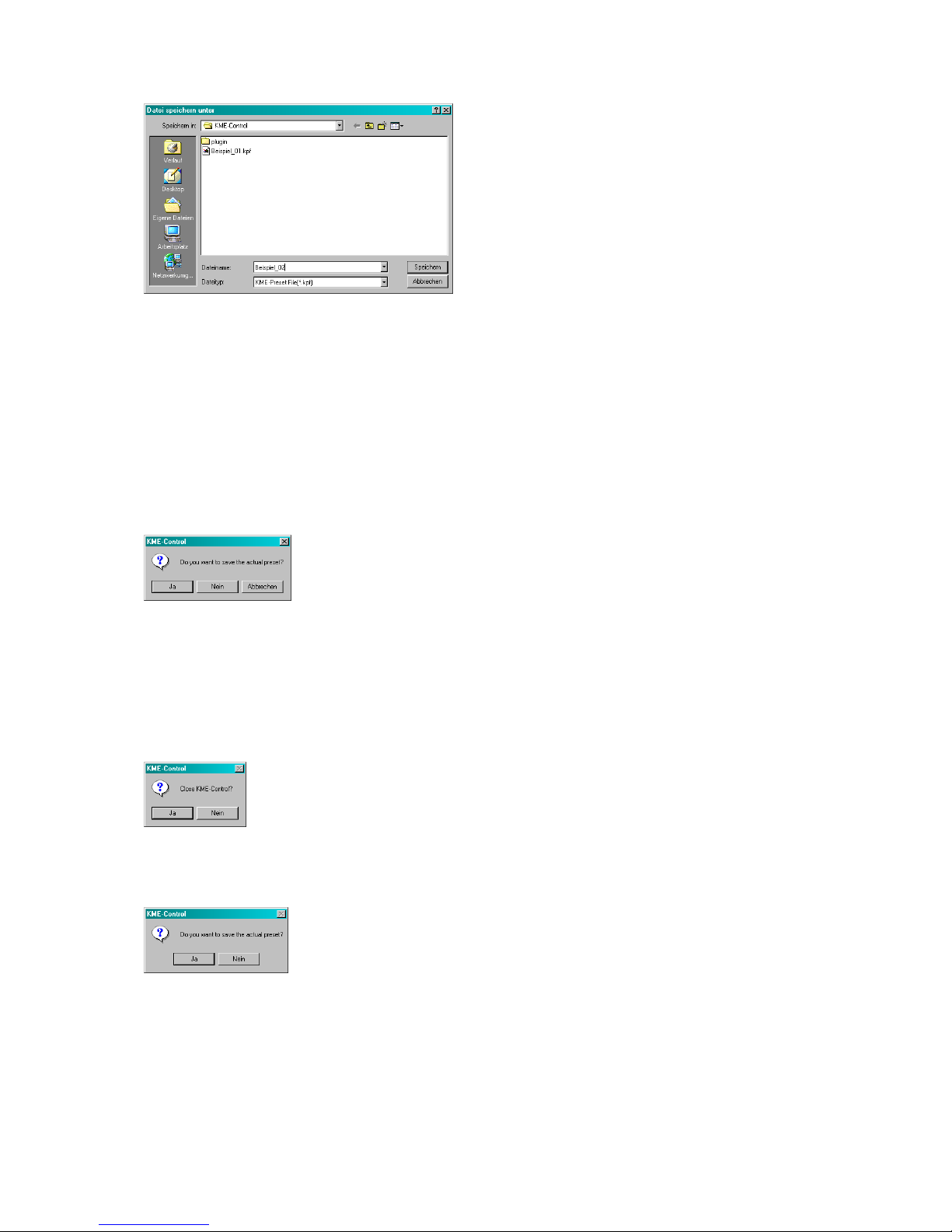
Select a file name for your preset that shall be saved, and click ‚Save’. We
recommend saving presets to the main KME Control installation directory. During
upgrades and de-installations of KME Control this preset files will not be deleted!
Close
Closes the active DAP 26 plug-in window. A dialogue appears to ask if you want to
save your last changes to the preset.
Selecting ‚Yes’ opens the ‚Save’ dialogue, ‚No’ closes the plug-in window and
‚Cancel’ returns to the plug-in window without changes.
Exit
Terminates the KME Control mainframe. You will be asked if you really want to exit.
Selecting ‚No’ returns to the program, ‚Yes’ terminates the program. If there are data
unsaved you will be asked to save or discard them.
If you are not sure that you did save your changes select ‚Yes’ and use the ‚Save’
function.
Page 29
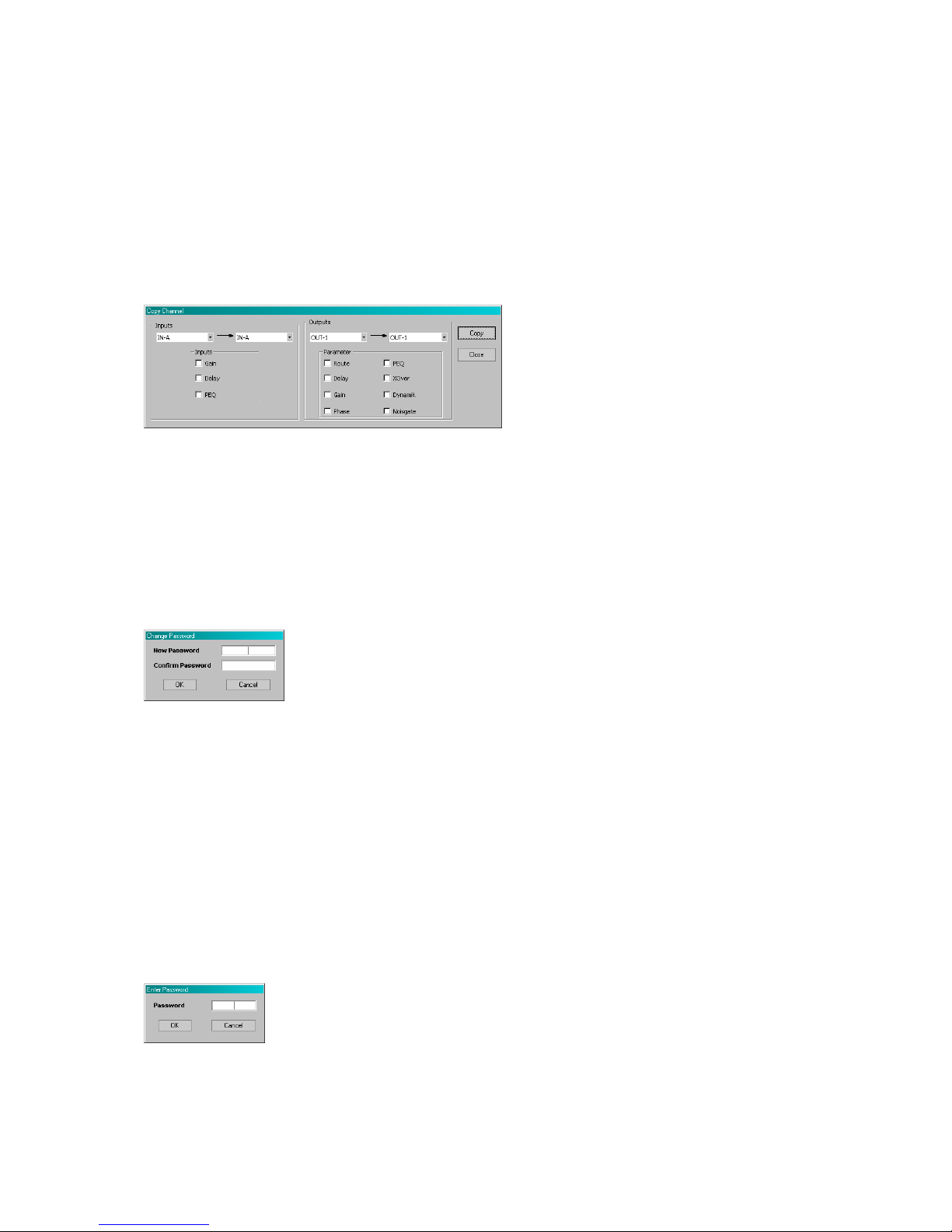
Tools (some tools are only activated in online mode)
Copy Channel Setup
Following example shows the usage of this clever tool:
Assuming you have created an input EQ curve and a master delay setting in Channel
A and you want to copy the same settings to channel B – just select ‘Input A’ Æ ‘Input
B’, select the modules you want to copy (here: delay and PEQ) and click the ‘Copy’
button – ready. Same procedure also works for the outputs.
Set Password (only in online mode)
The tool ‘Set password’ protects your DAP 26 from programming by other persons.
This may be useful for a rental system to prevent the customer from changing the
settings and possibly damaging parts of your PA system. Setting a password is quite
easy: Go online to the connected DAP 26 first and then select ‘Set password’. The
following window should appear:
Enter a 4-digit (only numbers are accepted) password in the field ‚New password’.
Enter the password again into the field ‘Confirm password’ and press ‘OK’. Your DAP
26 is now password-protected.
When trying to connect the DAP 26 to the computer again you are asked for the
password to enter. Without this password you can not change any setting in your
DAP.
Changing or deactivating the password is just as easy: Connect the DAP to the
computer and activate online connection. You are asked for the password. Enter the
password and select ‘Set password’ in the menu. Enter NO password in the field
‘new password’ and click ‘OK’. The password will now be deleted.
Enter NO password in the field ‘New password’ and click ‘OK’. The password will now
be deleted.
Page 30
Attention!
If you forget the password there is NO chance to re-activate the unit unless you send
it in to the K.M.E. support for factory re-initialisation. All user data (presets,…) inside
the unit will be lost afterwards.
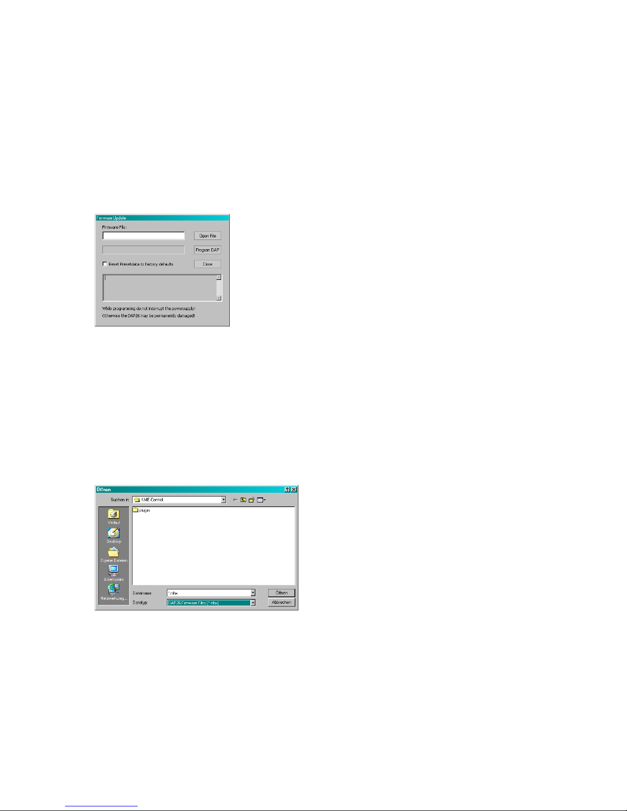
Firmware Update
For future upgrades of your DAP 26 you can use the firmware update which renews
the DSP software inside the unit.
The firmware update is easy to do. If you have received a new firmware file with an email from the K.M.E. support or by download from the Internet you can program it to
your hardware using the ‘Firmware update’ procedure from the main menu. If there is
a firmware update manual included to the firmware download please read this file first
and follow the manual whilst doing the update procedure.
Attention! The unit must be connected using RS 232 COM port. Firmware update is
NOT possible by using CAN connection.
Click ‚Open File’ and navigate to the location of the new firmware file (*.mhx).
Klick ‚Open’ and then ‘Program DAP’. Do EXACTLY the action the program is asking
you to do. Transmitting the firmware to the DAP may take several minutes.
Attention!
Do not interrupt the mains power and/or the serial connection between the DAP and
your computer during the update process. Avoid running unnecessary programs on
your computer during the update.
Page 31
After the DAP has received the complete new firmware it does the update procedure
and the new functions will be ready after powering the unit off and on again.
Remote Watch (only available in online mode)
The function module ‚remote watch’ shows the front of a remote located DAP 26 with
its meters and output gain pots in real-time. In this mode the user may control
input/output levels or compressor/limiter thresholds from the remote location (only
useful when connecting the units by CAN Bus for distances up to 400 meters).
Quick Setup
The menu ‚Quick setup’ contains pre-prepared configurations for various PA
applications. They include routing and crossover standard settings for all channels.
This may save time creating new set-ups. To load a set-up from the list just click on
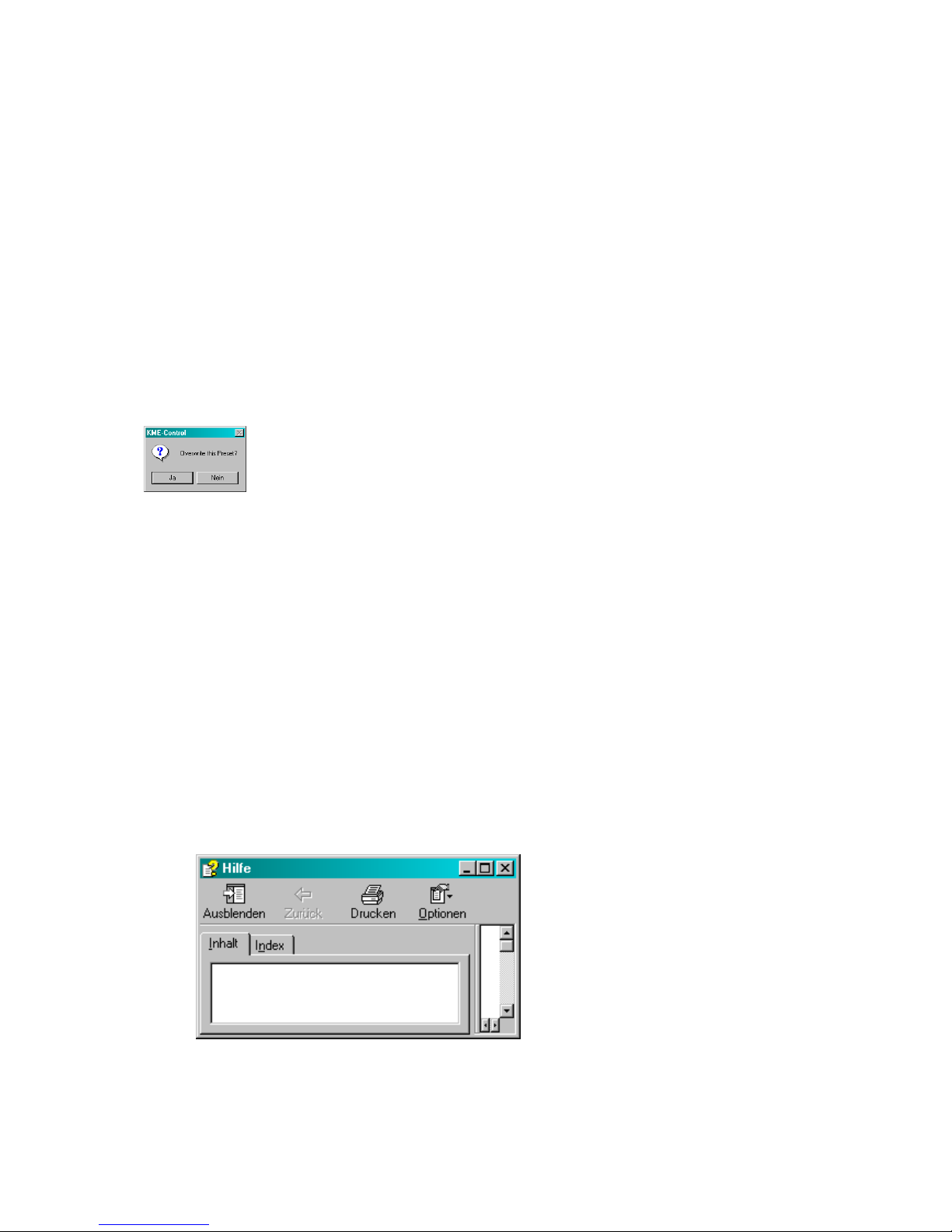
it. You are being asked if you want to overwrite the actual preset.
Select ‚No’ if you want to save your actual preset first. Selecting ‘Yes’ loads and
initialises the selected set-up. The different quick set-ups are described in the
appendix ‘Quick Setup’.
Window
You find window-based commands like ‘New Window’, ‚Cascade’, ‚Tile’ and ‚Arrange
Icons’ in this menu. Use them to change the style of display on your PC screen.
Help
Help Topics
This menu opens the help window containing a quick reference to most program
functions.
You can terminate the help window using the ‚Close’ button on the top right corner.
Page 32

About DAP 26
The ‚About’ function shows the version number and revision of the DAP 26 plug-in.
This information may be required contacting the K.M.E support.
Click ’OK’ to close this window or click the blue link to visit the K.M.E. homepage
(requires active Internet connection).
Page 33
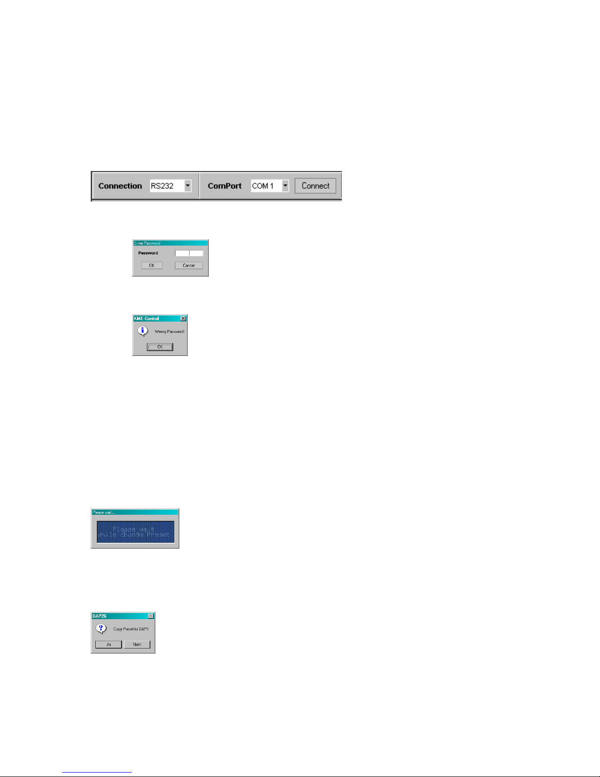
Going ’Online’ (using RS 232 as an example)
(assuming the communication line RS232 is already connected and working)
Set the ‚Connection’ field of the DAP 26 plug-in to ‘RS232’ and the ‘Com Port’ field to
‘COM1’ (or the COM port your DAP 26 is connected to). Click ‘Connect’.
If you did set a password in a previous session you will be asked for it..
Enter the 4-digit password and click ‚OK’ to start the connection.
After entering a wrong password you will get a notice window for two times.
You have three trials, after that you need to restart the software and initialise
the communication again. If you forgot the password you will have to send
the hardware unit to the K.M.E. support for factory re-initialisation.
Please refer also to the chapter ‚Set password’ of this manual!
If everything is OK with the communication the following window will appear, showing
that data is exchanged between the DAP 26 and your PC.
If the connection is set-up, you are being asked if you want to copy the actual preset
(which you probably just made in your PC) to the DAP 26. Click ‘Yes’ if you want to
do so.
If you select ‚No’ you can load a preset from the DAP 26 to make changes. Before
any data is loaded from the hardware unit to your PC you are being asked if you want
to save your actual work.
Page 34

Selecting ‚Yes’ opens the ‚Save’ dialogue, selecting ‚No’ starts the transmission of
the presets from the DAP 26 to the PC. You can select the number of the preset to
change.
While you are in online mode you cannot change any settings in the DAP 26 by
hardware. The unit is locked, the display shows:
UNIT LOCKED due to
PC CONNECTION
or RESTART to unlock
DISCONNECT from PC
To make settings on the hardware unit you have to go ‘Offline’ pressing the
‘Disconnect’ button.
Clicking into the ‚Preset’ list box allows the user to load another preset into the
software plug-in by selecting one out of the list.
The selected preset will be loaded.
When you have made your changes to the preset you can save the preset in the
hardware unit by clicking the ‚store preset’ button. The software sends the preset
back to the DAP 26 and stores it in the internal memory.
When there is a communication problem between the DAP 26 and your PC the
following window will be displayed:
Page 35

There might be one (or more) of the following problems:
• the DAP 26 is switched off
Solution: switch ’on’ the DAP you want to communicate with
• the DAP 26 is not connected to the selected COM port
Solution: check the connection between the DAP 26 and your computer. Did
you use the correct COM port? Is there any software to be installed using a
USBtoRS232 converter on systems without ‘native’ COM ports (refer to the
manual of the specific converter).
• COM port is used by another application
Solution: Some programs, especially serial MIDI device drivers block COM
ports. If possible deactivate all programs you do not need at the time you want
to use your computer programming a DAP 26. Try using another COM port or
use a USBtoRS232 converter connected to the USB port of your computer.
• You are using the wrong cable
Solution: Do only use cables according to the K.M.E. specification to avoid
communication errors or even damages of both the DAP 26 or your computer.
• You are using the wrong communication port on the DAP 26
Solution: Only use the upper connector labelled ‚RS232/CAN’ for serial
communication with a PC COM port. Make sure that nothing is connected to the
lower port in RS232 mode!
• The DAP 26 is not in RS 232 mode (LED does not light)
Solution: Operate the switch beside the connectors to activate RS 232 mode.
The yellow LED must light up if you want to use RS 232 communication.
• There is another problem...
Solution: Contact the K.M.E. support.
Page 36
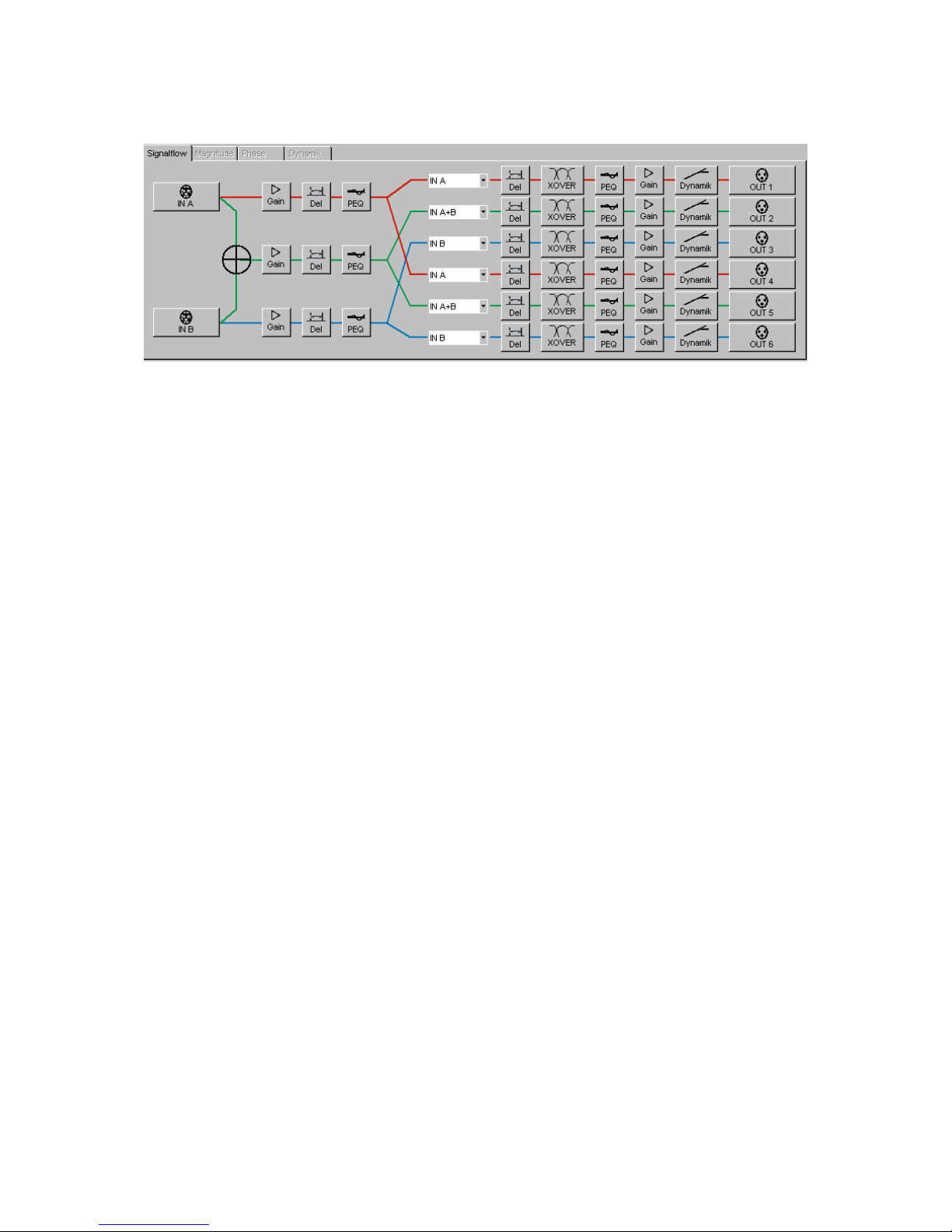
Signal Flow
The register tabs can be accessed out of all functional modules. The tab ‘Signal flow’
includes the routing matrix and the activation of all other audio modules by clicking.
Magnitude
The tab ‚Magnitude’ is active within the modules ‘Equalizer’ and ‘Crossover’ and
shows the frequency response of the selected channel affected by crossover
networks and / or filters. This tab includes drag-and-drop functionality with the
mouse.
Phase
The tab ‚Phase’ is active within the modules Equalizer and Crossover and shows the
phase response of the selected channel affected by crossover networks and/or filters.
Drag-and-drop is deactivated on the ‘Phase’ tab.
Dynamic
The register tab ‚Dynamic’ is activated in the dynamic processor module only. It
shows the characteristic of the selected compressor/limiter function.
Page 37
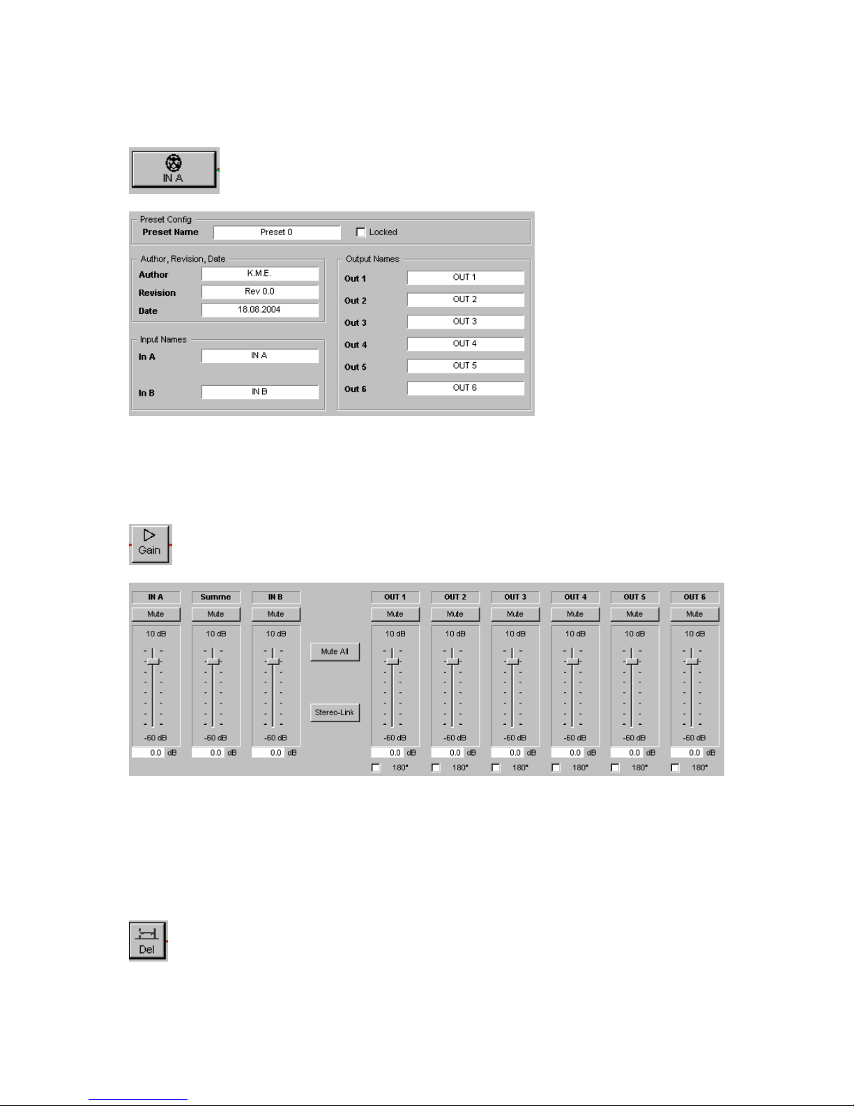
Functional units
In/Out
In this window the user can rename the input and output lines of the processor or
name the actual preset and add information about author/date. The values are stored
in the hardware unit and can be read out by other users.
Gain
In this window the input / output levels can be either set by mouse, writing the
specified gain value in the ‘dB’ field or using the cursor keys for fine adjustment of the
pre-selected fader. You can operate the ‘Mute’ buttons, ‘Polarity’ switches and
‘Stereo link’ / ‘Mute all’ buttons as desired.
Delay
Page 38
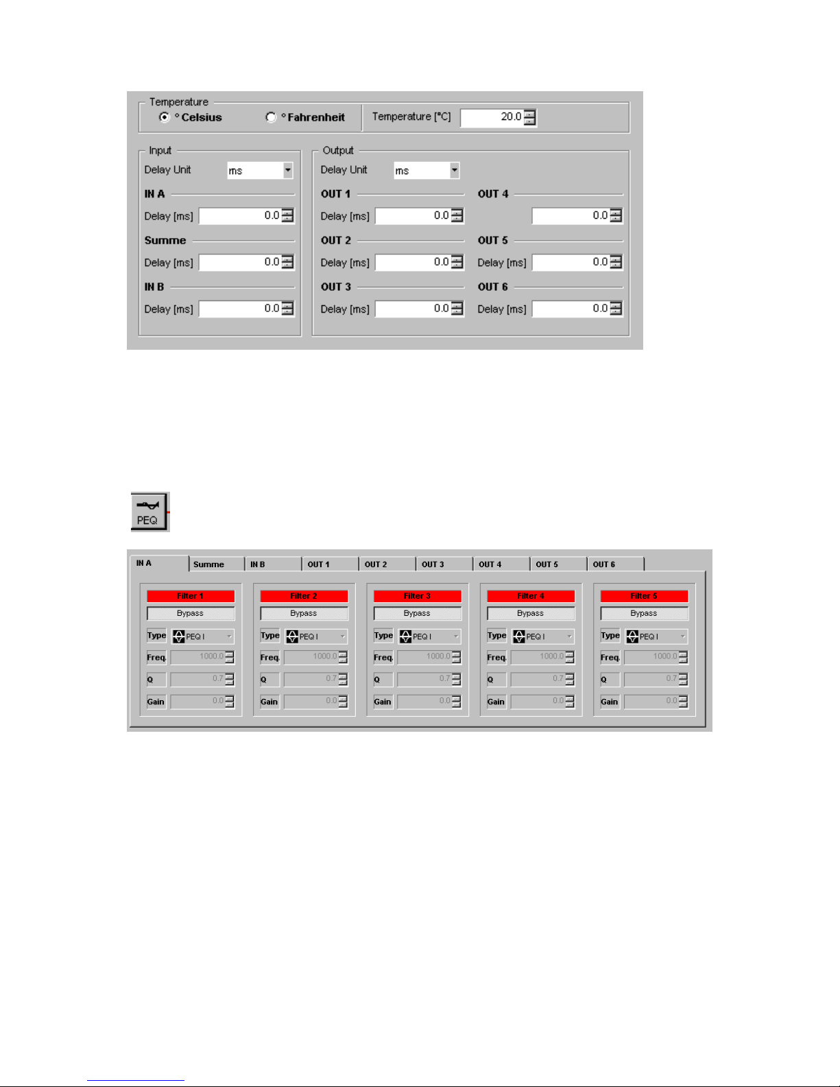
In this window you can set the time delays for all channels. This can either be done
by clicking the up/down arrows behind the fields or entering the delay values into the
fields. As delay units you can select µs, ms, s, cm, m and feet. While the sound
velocity is depending on temperature, this field corresponds to the delay units cm, m
and feet.
Equalizer
In this window you find 9 register cards where you can make the EQ settings for the
corresponding channel. For each channel you may combine any 5 filters of the
available filter types. The filter types are described in the chapter ‘filters’. To activate
a filter, first select the channel in which you want to add the filter by selecting a
register card. Then activate one of the 5 filters by clicking into the grey ‘Bypass’ field
below the red field labelled ‘Filter X’. This field will change to green to signalise the
filter is working.
Select in the field ‘Filter type’ the filter algorithm you want to use and adjust the
values for ‚Freq.’, ‚Gain’ and. ‚Q’.
Select the register card ‚Magnitude’ to view the influence of the activated filters to the
frequency response of the selected channel.
Page 39
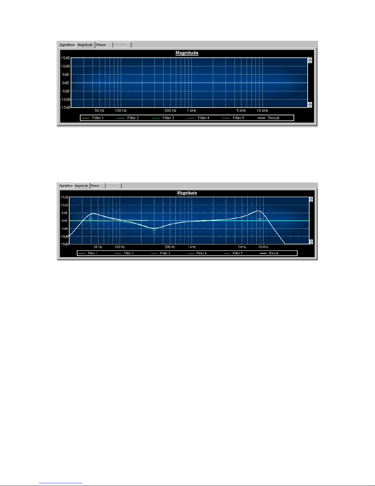
The coloured triangles are named with the specific filter number. It is possible to
move this points with the mouse and monitor the acoustic changes in real-time after
releasing the mouse button when the DAP26 is online.
Here is an example how to create a “classic”, mixing desk- type equalizer using the
filter banks of the DAP 26:
Page 40
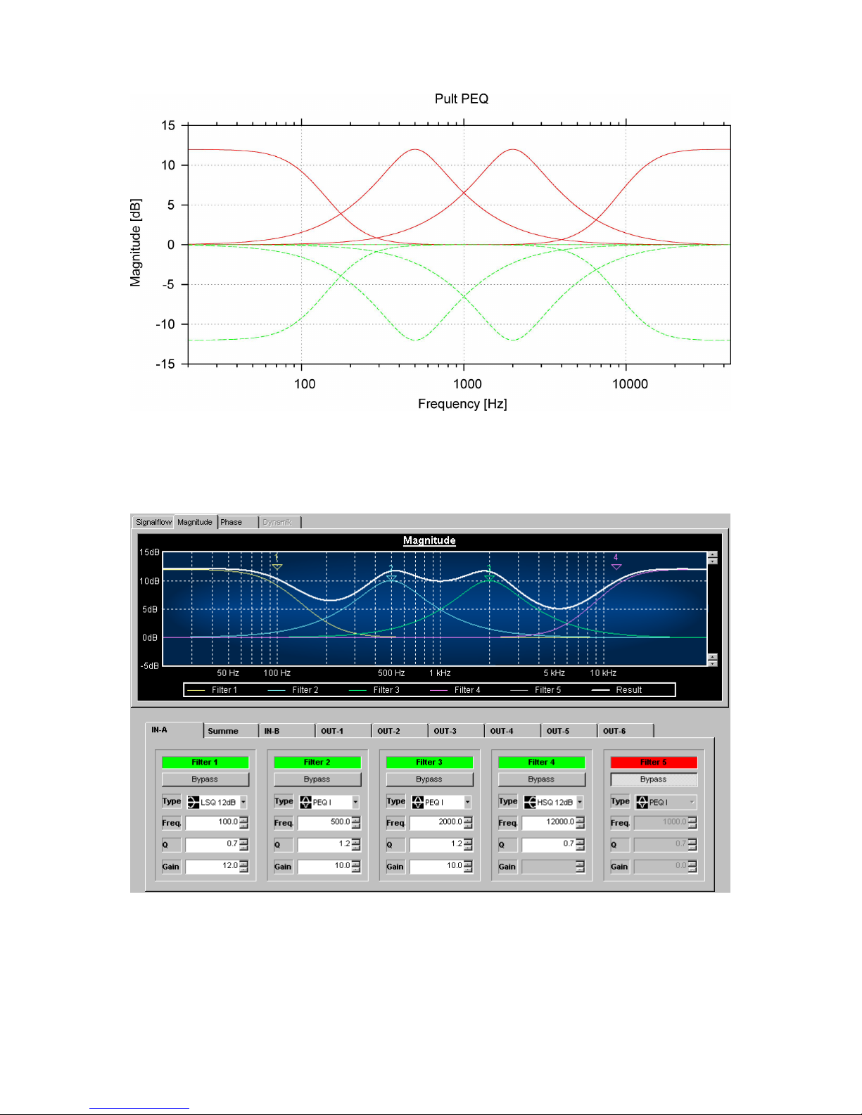
Filters 1-4 are to be set to the values specified below. The remaining filter could be
used as a Low- Cut i.e. at 80 Hz.
Page 41
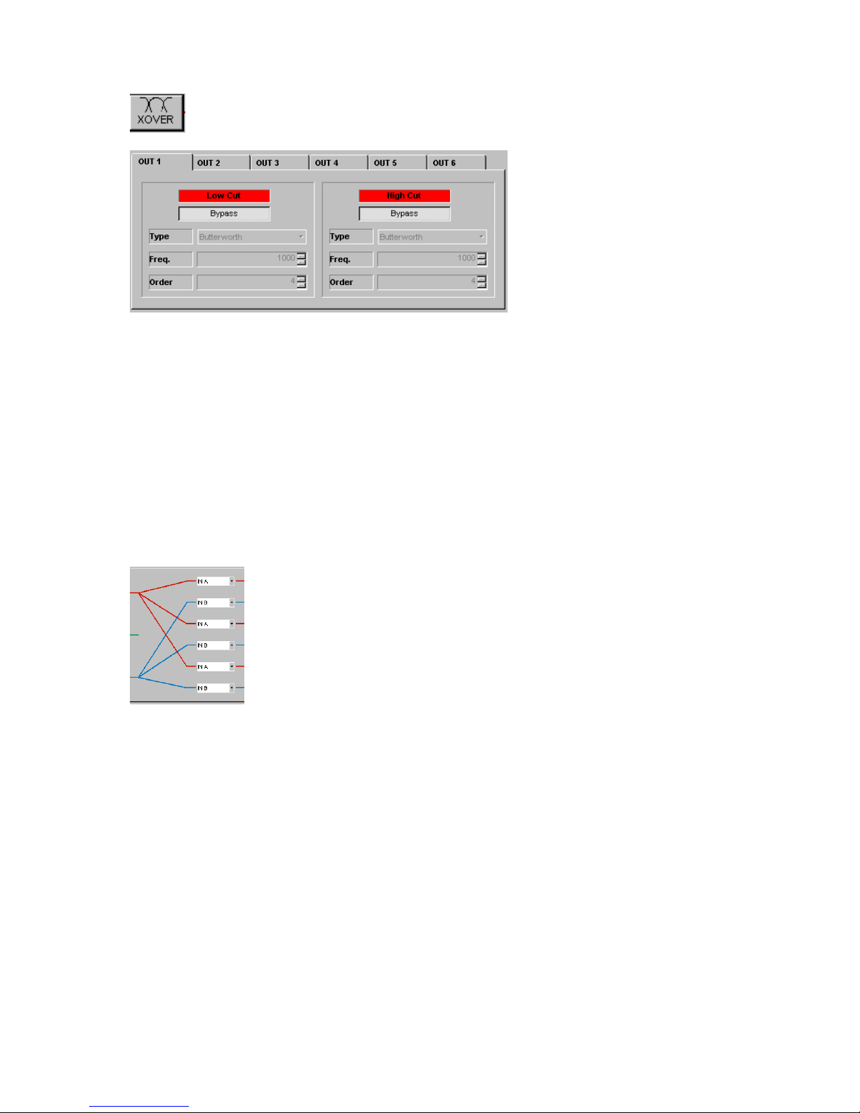
XOVER
In this window you find 6 register cards for setting up the crossover functions of the
output channels. Each filter bank consists of a ‘LowCut’ and a ‘HighCut’ type filter
which can be activated and programmed to your needs.
The set-up of the crossover section shall be described using an easy example:
Assuming that you want to set output channels 1&2 for the bass and 3&4 for the
mid/high systems.
Prior to the crossover adjustment you already set the correct signal flow in the routing
matrix (see below).
To assign an output to a “bass” channel simply activate the ‚High Cut’ Filter by
clicking into the grey ‚Bypass’ button below the red control field labelled ‘High Cut’.
This field will change to green when the filter is activated.
We recommend using the filter type ‘Linkwitz- Riley’ for any standard crossover
applications. For this example set the filter frequency to 120 Hz. This can be done by
entering ‘120’ into the ‘Freq.’ field or by using the mouse in the graphical ‘Magnitude’
display clicking on a curve and dragging it to the correct position. This operates in
real-time when the DAP 26 is online.
This example would look in the software like this:
Page 42
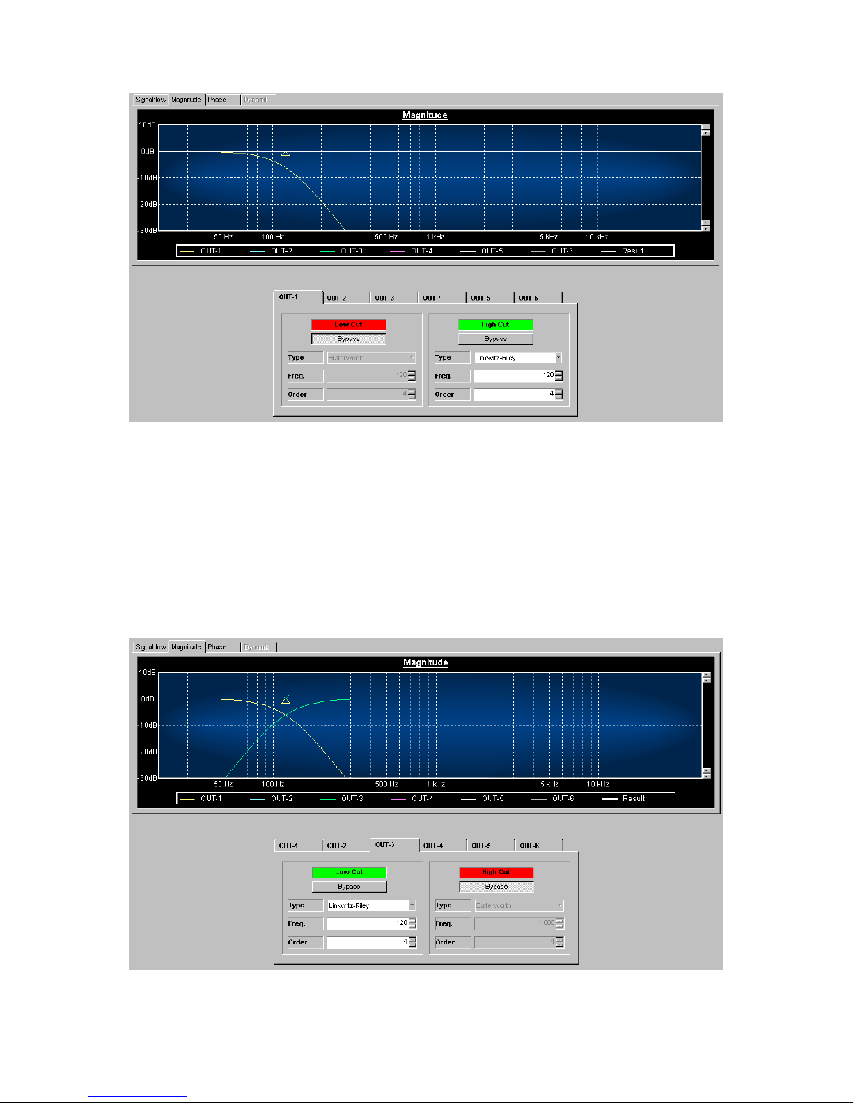
As you can see the output channel 1 contains only the bass frequencies below
120Hz.
The settings may be copied to channel 2 using the ‚Copy Parameter’ dialogue or
setting it manually.
To operate channels 3&4 as Mid/High outputs proceed as described above but use
the ‘Low Cut’ Filter instead using the same parameters.
This setting would look like this:
As you can see the output channel 1 contains only the bass frequencies below
120Hz.
Page 43
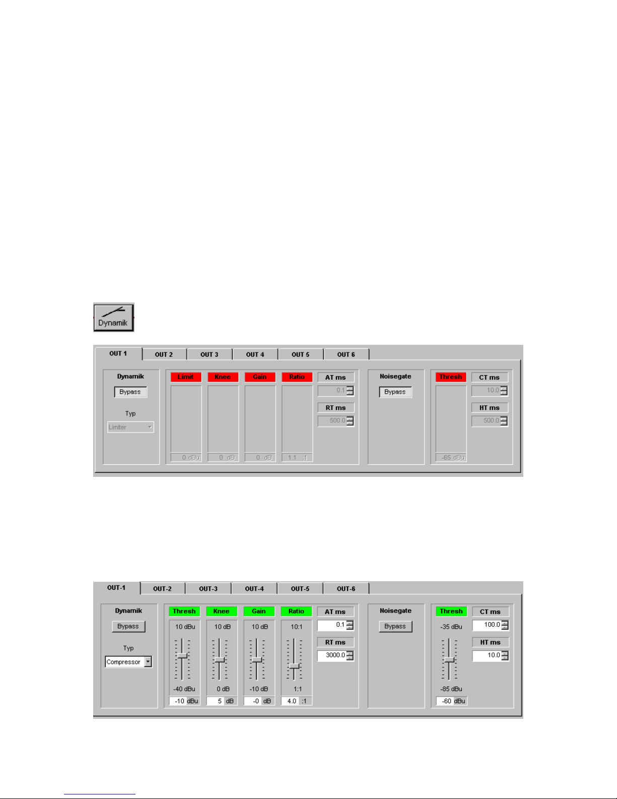
The settings may be copied to channel 4 using the ‚Copy Parameter’ dialogue or
setting it manually.
Æ The same result you may obtain much easier by using the ‘Quick Setup’ dialogue
(here: ‘2 Way Stereo’)!
Attention!
For inexperienced users we do not recommend „experimenting“ around with the
crossover section when you are online with the DAP 26 and a sound system is
connected and running. In this case all settings are transmitted to the DAP in realtime and a ‘wrong’ filter may damage the speakers.
Dynamik
In this window you can activate the dynamic processing units of all output channels.
To activate a dynamic processor simply select the register card of the channel you
want to process and click the grey ‘Bypass’ button. The red fields will change to
green when the processor is activated.
Page 44
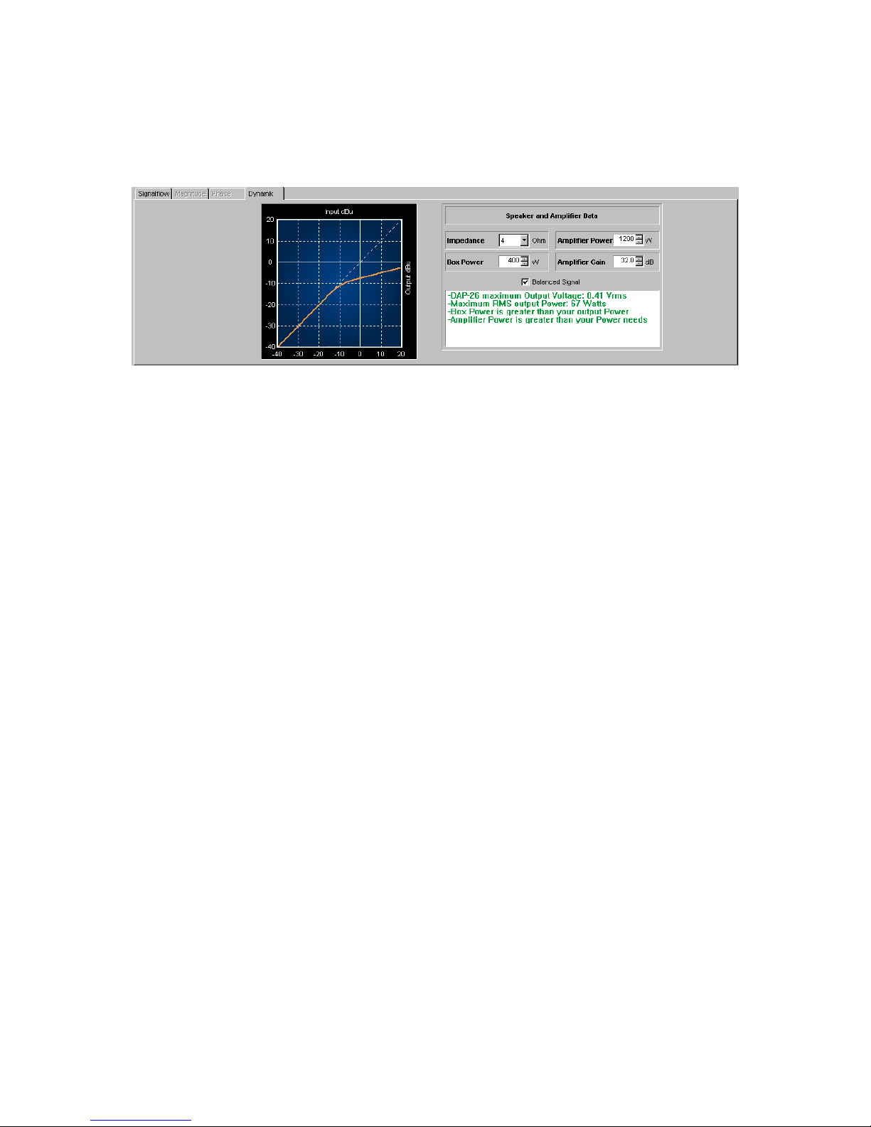
The ‚Dynamic’ Window displays the response of the selected dynamic processor and
includes a simple but informative level calculator.
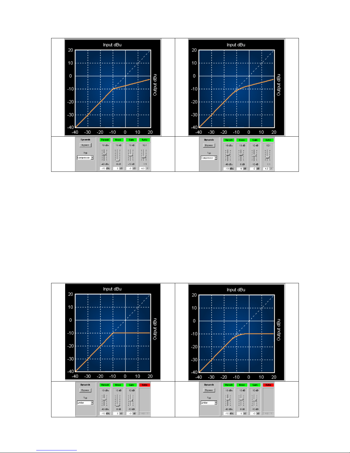
In the following some set-ups together with the corresponding curves are shown:
a) Compressor
The compressor behaves linear up to the adjusted ‚Threshold’ value. If this value is
reached the compressor begins to control the level according to the compressing
‘Ratio’ selected. If the ratio is i.e. 4:1 then the level has to increase by 4 dB to allow
the output increasing by 1 dB. This is the ‘compression’ mentioned. With higher ratio
settings, the compression will be more ‘audible’ (which must not be negative at all).
The ‘Knee’ value describes the point where the compression starts. A knee value of 0
starts the compression exactly at the threshold level. A higher knee value allows to
start compression more softly, normally less audible.
Page 45
b) Limiter
A limiter describes a compressor with a compression ratio of 1:infinite what does
mean that no level above the threshold is allowed to pass. Limiters are used for
maximum protection of speaker components or maybe for securing maximum sound
pressure levels prescribed by law. The ‘Knee’ value is comparable with the
compressor too. Higher knee values allow to start limiting more softly, normally less
audible.
Page 46
Attack Time
Release Time
This time-constants show the speed of the regulation process inside the compressor /
limiter algorithms. A longer ‘Attack’ time will let some peaks pass before
compression / limiting occurs which may increase the average SPL level while a
short attack time will give more overload protection to the components. The ‘Release
time’ should be adjusted to the program material used.
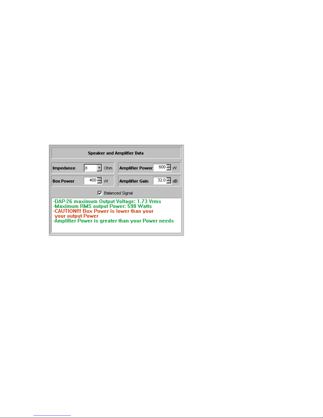
Speaker and Amp Parameter
In this window you find a level / power calculator.
The values entered in this window do not affect the outputs at all but give useful
information about the correct threshold level in the dynamic section together with the
output level of the selected channel.
c) Noisegate
The noise gate can be activated by clicking into the grey ‚Bypass’ field. The threshold
slider will occur and the control field will change the colour to green when the noise
gate is activated. The operation is easy – just set the threshold level (the minimum
sound level above i.e. disturbing background noise). All audio material with a level
below the threshold value will be faded out to silence, audio material above the
threshold will not be processed.
The parameters ‚Hold Time’ und ‚Close Time’ affect the regulation process. ‘Hold
Time’ describes the time the unit „waits“ before fading out signals below the threshold
level and the ‚Close time’ describes the speed of the fade-out. Set this constants to
taste depending to the program material transmitted.
Page 47
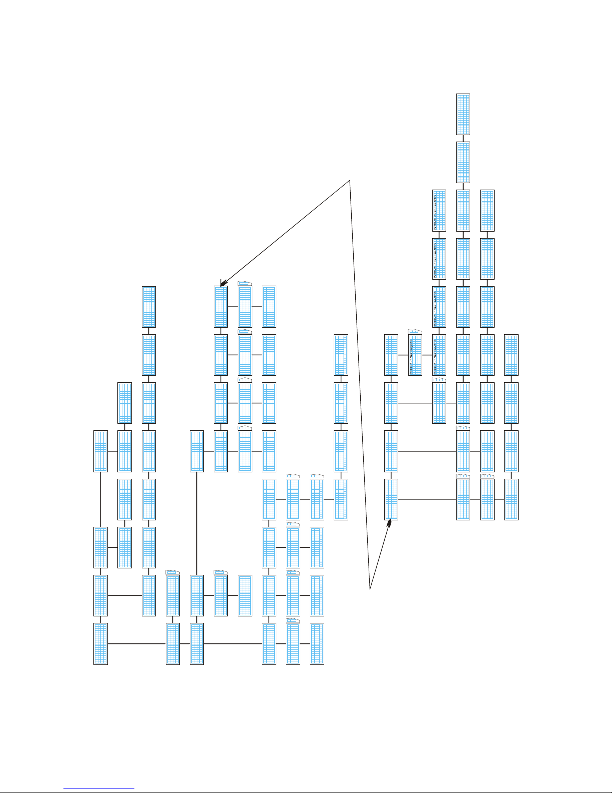
Appendix – navigation structure on the hardware unit
PrXX/Output
Delay
Choose an option! ¦>
PrXX/Output
Mute
Choose an o ption!<¦>
PrXX/Output
Gain
Choose an option!<¦>
PrXX/Output
Phase
Choose an optio n!<¦>
PrXX/Out/Delay
Channel 1
Choose a Chan nel ¦>
PrXX/Out/Del/Ch 1
Value : 0.00ms
OK: change value! ˆ
PrXX/Out/Mute
Channel 1
Choose a channel ¦>
PrXX/Out/Mute/Ch 1
Value : M ute OFF
OK: Change Valu e ˆ
PrXX/Out/Gain
Channel 1
Choose a Channel ¦>
PrXX/Out/Gain/Ch 1
Value : 0.0 dB
OK: Change value! ˆ
PrXX/Output
Phase : 0 °
OK: Change Valu e! ˆ
PrXX/Out/Phase
Channel 1
Choose a channel ¦>
K.M.E. DAP26
Presetinfo
Choose an option!‹ ›
ˆ
Presetinfo: Author
<To n-Tech>
Choose an Info <ˆ>
Presetinfo: Pr.-Name
< No-Name>
Choose an Info ˆ>
Presetinfo: Pr.-Lock
Disabled
Choose an Info <ˆ>
Presetinfo: Ch-Names
Input A: < IN-A>
Choose an Info <ˆ>
Input B: < IN-B>
Prese tinfo: Ch -Names
Outpu t 1: < OUT- 1>
Choose an Info <ˆ>
Outpu t 2: < OUT- 2>
Prese tinfo: Ch -Names
Output 5: < OUT- 5>
Choose an Info <ˆ
Output 6: < OUT- 6>
Presetinfo : Ch-Names
Outpu t 3: < OUT-3>
Choose an Info <ˆ>
Outpu t 4: < OUT-4>
Preset: XX
Outputchannels
Choose an option!<¦
Presetselection
Preset: XX
Active Preset <¦>
Presetselection
Preset: YY
OK: Load Pr eset <¦>
K.M.E. DAP26
Devicesetting
Choose an opt ion!‹ ›
ˆ
Devicesettings
Net-ID : 1
OK: Change Value <ˆ
Devicesettings
In-select: Analog
OK: Change Va lue ˆ>
PrXX/Inputs
Delay
Choose an option! ¦>
PrXX/In/Delay
Channel A
Choose a Channel ¦>
PrXX/In/Del/Ch A
Value : 0.00ms
OK: chang e value! ˆ
PrXX/In/Mute
Channel A
Choose a Channel ¦>
PrXX/In/Mute/Ch A
Value : Mute OFF
OK: change value! ˆ
PrXX/Inputs
Mute
Choose an option!<¦>
PrXX/Inputs
Gain
Choose an option!< ¦>
PrXX/In/Gain
Channel A
Choose a Channel ¦>
PrXX/In/Gain/Ch A
Value : -0.0dB
OK: change va lue! ˆ
PrXX/In/Fil/ChA
FilterNr. 1
Choose a Filter ¦>
PrXX/In/Fil/ChA
Typ : Bypass
OK: Change value ˆ>
PrXX/In/Fil/ChA
Q : 0.7
OK: Change value <ˆ>
PrXX/In/Fil/ChA
Frequency: 1000Hz
OK: Change value <ˆ>
PrXX/In/Fil/ChA
Gain : 0.0dB
OK: Change value <ˆ
PrXX/Inputs
Filter
Choose an option!<¦
PrXX/ In/Filt er
Channel A
Choose a Ch annel ¦>
Preset: XX
Inputchannels
Choose an option! ¦>
Devic einfo: Re vision
X.X
Choose an Info <ˆ
Deviceinfo: S/N
123456
Choose an Info ˆ>
K.M.E. DAP26
Deviceinfo
Choose an option!‹
ˆ
PrXX/ROUTING
Channel1
Choose Outchann el ¦>
PrXX/Route/Ch1
Input A
OK: Change Input ˆ
Preset: XX
Routing
Choose an option!<¦>
K.M.E. DAP26
Preset Configur ation
Choose an opt ion! >
ˆ
...
...
...
...
...
...
...
...
...
...
...
PrXX/Output
Filter
Choose an option!<¦>
PrXX/Output
X-Over
Choose an option!<¦>
PrXX/Output
Dynamic
Choos e an option !<¦>
PrXX/Output
Noisegate
Choose an option!<¦
Channel 1
Choose a channel! ¦>
Typ : Bypass
OK: Change value ˆ>
Threshold: -60dB
OK: Change value <ˆ>
Close : 100ms
OK: Change value <ˆ>
Hold : 10ms
OK: Change value <ˆ
PrXX/ Out/Dyn amic
Channel 1
Choose a channel ¦>
PrXX/ Out/Dyn /Ch1
Typ : Limiter
OK: Change value ˆ>
PrXX/O ut/Dyn /Ch1
Thres hold: -6.0dB
OK: Change value <ˆ>
PrXX/Out/D yn/Ch1
Gain : 0.0dB
OK: Change value <ˆ>
PrXX/Out/D yn/Ch1
Knee : 1dB
OK: Change value <ˆ>
PrXX/O ut/Dyn /Ch1
Ratio : 1.0:1
OK: Change value <ˆ>
PrXX/Out/D yn/Ch1
Attack : 0.1ms
OK: Change value <ˆ>
PrXX/O ut/Dyn /Ch1
Releas e : 3000ms
OK: Change value <ˆ
PrXX/Out/X-over
Channel 1
Choose a channel ¦>
PrXX/Out/X-over/Ch1
LP-Typ : Bypass
OK: Change Value ˆ>
PrXX/ Out/X-o ver/Ch 1
LP-Freq. : 1000 Hz
OK: Change Value <ˆ>
PrXX/Out/X -over/Ch1
LP-Order : 4
OK: Change Value <ˆ>
PrXX/O ut/X-o ver/Ch 1
HP-Typ : Bypass
OK: Change Value <ˆ>
PrXX/Out/X -over/Ch1
HP-Freq. : 1000 Hz
OK: Change Value <ˆ>
PrXX/O ut/X-o ver/Ch1
HP-Order : 4
OK: Change Value <ˆ
PrXX/Out/Filter
Channel 1
Choose a channel ¦>
PrXX/ Out/Fil /Ch1
FilterNr. 1
Choose a Filter ¦>
PrXX/ Out/Fil /Ch1/F i1
Typ : Bypass
OK: Change value ˆ>
PrXX/Out/Fil/Ch1/Fi1
Frequency: 1000Hz
OK: Change value <ˆ>
PrXX/ Out/Fil /Ch1/F i1
Q : 0.7
OK: Change value <ˆ>
PrXX/Out/F il/Ch1/Fi1
Gain : 0.0 dB
OK: Change value <ˆ
...
...
...
...
...
Page 48

Appendix – Technical Data
Technical Data DAP 26 / 96
Inputs
Analog inputs 2 (XLR)
Input impedance balanced 20 kOhm
max. input voltage 12 / 18 dBU
Outputs
Analog outputs 6 (XLR)
Output impedance balanced 130 Ohm
max. output voltage 12 dBU
Processor
DSP 2 x 32 bit floating point, 100 MHz clock
Maximum Ground delay 0,7 ms
Sampling 24 bit / 96 kHz
converters 128 x Oversampling
Digital input AES/EBU / SPDIF with
Format-/ Sample rate converter
Dynamic range Analog Input to Output >108 dB (A)
Distortion (THD)
< 0,001%
Preset Memory User presets 32
Software for PC mit Windows 2000, XP
PC connection
serial (RS 232) 9 pin
details displays 8-digit LED chains for inputs and outputs
backlighted LCD- Display
knobs Navigation pad, mains switch, Gain pots
Special features Remote control using RS 232 or CAN Bus
Power Switched mode power supply 90 - 250 Volt / 50 - 60 Hz
dimensions (mm)
483 x 44 x 330
weight (kg) 5
Page 49

For your notes:
Page 50

Page 51

Page 52

Klingenthaler Musikelektronik GmbH
Auerbacher Straße 268
08248 Klingenthal / Germany
phone +49 (0)37467 - 558-0
fax +49 (0)37467 - 558-33
www.kme-sound.com
[email protected]
Technical State February 2005.
The content corresponds to the state at printing. Subject to technical alterations. Misprints and errors expected.
Feb 2005 / SL
 Loading...