

Page 1

Digital Designer’s Guide
Application Note–AN0604D
Revision B
Tips for connecting 24-volt power
This application note covers choosing a transformer and connecting
24 volt AC power to a KMC Controls DDC controller.
Multiple factors must be considered before choosing and connecting a
transformer to power a KMC controller. This application note provides
information to help system designers and installers make decisions about
powering controllers with transformers and then installing them correctly.
Choosing a
transformer
Danger
You can be killed or seriously injured if you contact live, high voltage circuits.
Disconnect AC mains and follow all local lock-out and tag-out procedures
when connecting or working on transformers.
Most KMC controllers require a 24-volt, AC power source for operation. The
recommend source for power is a UL listed, Class 2 transformer. When choosing a
transformer, consider the following:
◆ Mounting
◆ Primary voltage
◆ Secondary voltage
◆ Load capacity
1–15
Page 2

Tips for connecting 24-volt power
Choosing a transformer
Mounting Transformers supplied by KMC Controls may be either foot or
knock-out mounted. Foot mounting is usually used inside of an enclosure.
Knock-out mount attaches the transformer directly to a conduit fitting such as a
cover plate for a handy-box.
Primary voltage The primary voltage rating of the transformer must match the
voltage of the AC mains to which it will connect. Transformers are manufactured
for either a single primary voltage such 120 or 240 volts or multiple voltages. The
two XEE–6000 series transformers in
primaries.
Circuit breaker
(optional)
Bracket for foot
mounting
Illustration 1 KMC XEE–6000 series transformer
KMC Controls
Threads for knock
out mounting
Illustration 2 are examples of both types of
Circuit Breaker
120 VAC
Common
Single voltage primary transformer
Secondary voltage The secondary voltage for KMC transformers is 24 volts AC.
Some transformers include an optional circuit breaker which protects the
transformer and wiring from current that exceeds the capacity of the circuit
components.
Load capacity The load capacity is a measure of how much power the
transformer can deliver to attached devices. This is usually expressed as VA, an
abbreviation for Volt-Amperes. See
additional information on transformer load capacity.
480 VAC
277 VAC
24 VAC
240 VAC
120 VAC
Common
Multiple tap primary transformer
Illustration 2 Transformer schematics
Calculating transformer size on page 1-21 for
Circuit Breaker
24 VAC
1–16
AN0604D Revision B
Page 3

Digital Designer’s Guide
Connecting to
controllers
Tips for connecting 24-volt power
Connecting to controllers
KMC Controls recommends supplying power to each controller from a
transformer dedicated to the controller.
Illustration 3 is a typical connection of a
KMC XEE–6000 series transformer connected to a KMC controller. The usual
practice is to connect the phase (usually blue) wire of the transformer secondary
to the phase or ~
terminal and the common (usually brown) wire connected to the
– or ground terminal. Other transformers may use a different color scheme.
Unless required by an electrical code requirement, do not ground either lead of
the secondary.
24 VAC120 VAC
Illustration 3 Connecting to a single controller
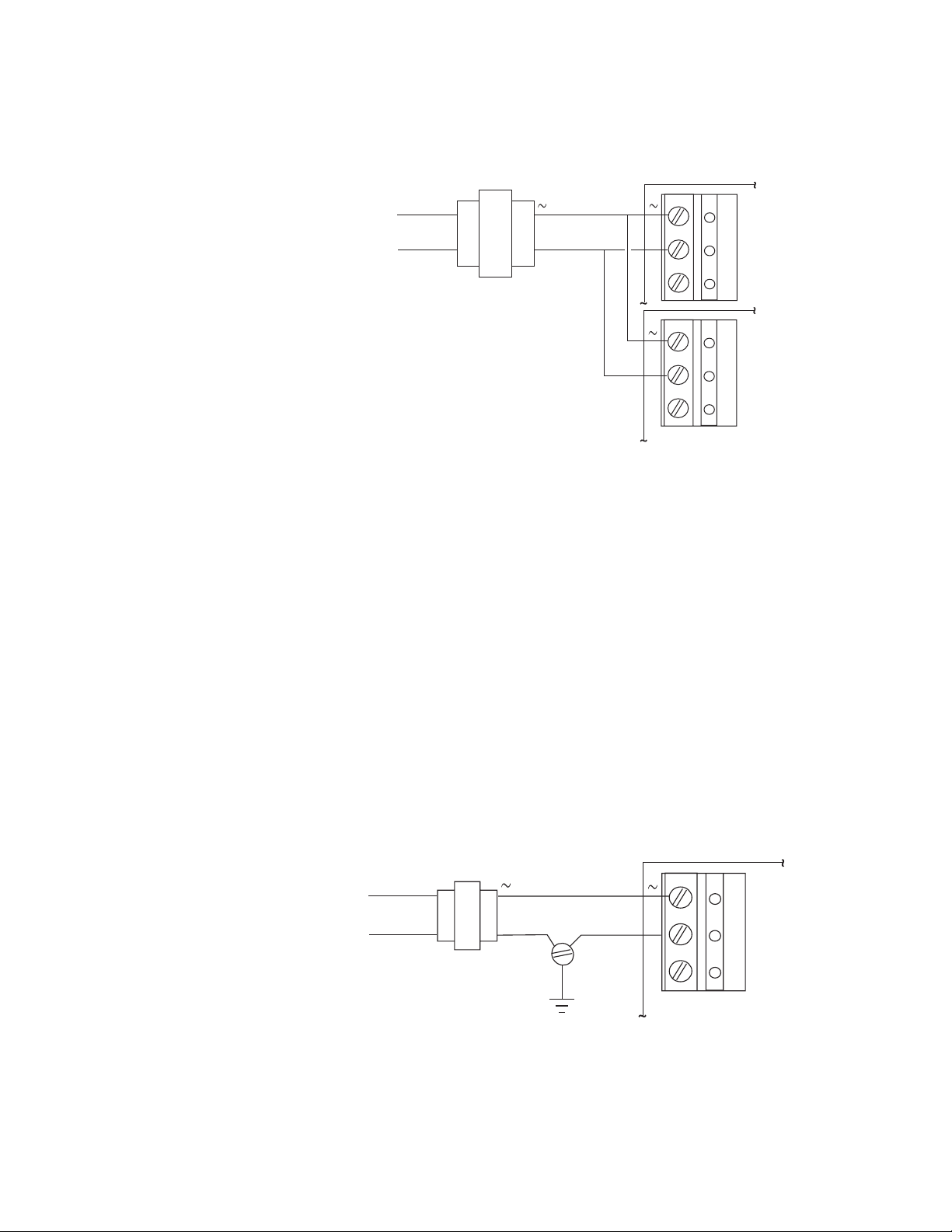
Connecting several controllers to a single transformer
When more than one controller must be powered from a common transformer,
connect as shown in
Illustration 3. In addition, observe the following
requirements:
◆ Connect the phase (~) terminals in parallel with other phase terminals and
the commons (–) in parallel with the other common terminals. See
Illustration 4.
◆ If the secondary must be grounded, ground it at only one location. See
Grounded secondary connections
◆ Connect only controllers with the same type of power supply. Controllers
on page 1-18.
with half-wave power supplies and full-wave power supplies cannot be
powered directly by the same transformer. See Grounded secondary
connections on page 1-18.
◆ Choose a transformer with the correct VA rating. See Calculating transformer
size on page 1-21.
◆ Choose a wire size that limits the voltage drop to no more than 5%. See
Calculating voltage drop
on page 1-22.
AN0604D Revision B
1–17
Page 4
Tips for connecting 24-volt power
Connecting to controllers
.
KMC Controls
24 VAC120 VAC
Illustration 4 Powering two controllers from one transformer
Grounded secondary connections
KMC recommends that secondaries of transformers powering network devices
be floating! Some conditions exist, however, that require that the secondary of a
transformer be connected to earth ground. In the United States, for example:
◆ The National Electrical Code® requires (section 250.20) grounding
transformers for AC systems of less than 50 volts if the primary voltage
exceeds 150 volts to ground or if the main transformer supplying power to
the building is ungrounded.
◆ Some municipal electrical codes more restrictive than the NEC may require
that the secondaries of all transformers that supply 24 VAC be grounded.
IF a grounded secondary is mandated, ground the common (–) wire from the
transformer to an equipment grounding screw in the equipment enclosure. If
more than one controller is powered from the transformer, ground both at the
same ground screw.
1–18
120 VAC
24 VAC
Illustration 5 Grounding the secondary of a transformer (when required)
AN0604D Revision B
Page 5
Digital Designer’s Guide
Tips for connecting 24-volt power
Connecting to controllers
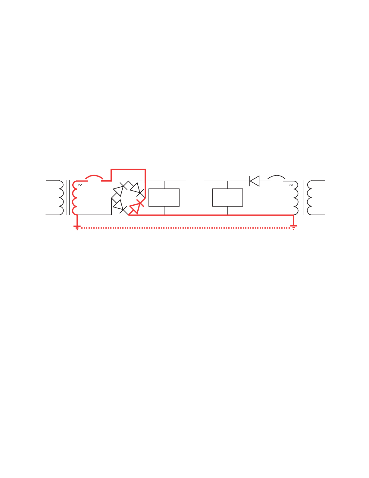
If grounded transformers are used on a network containing both full-wave
devices and half-wave devices, problems may occur because of the circuit
differences in the power supplies. The common connection (direct or indirect) on
the network and the grounds on the transformers may set up an inadvertent short
circuit. In the example shown in
Illustration 6 below, the transformer on the
full-wave device is shorted across one of the rectifier diodes during half the AC
cycle. Likely symptoms of such a situation may include:
◆ A circuit breaker or fuse opens.
◆ The power supply and/or transformer becomes overheated or damaged
.
Full-Wave Device Half-Wave Device
120 VAC
Common
Circuit
Breaker
++
24 VAC
Filter/
Regulator
Filter/
Regulator
Circuit
Breaker
24 VAC
Illustration 6 Shorting of circuit from connected (grounded) full-wave and half-wave devices
Even with grounded transformers, this should not be a problem:
◆ If all the devices are full-wave or all the devices are half-wave. (Nearly all
currently available KMC devices are half-wave.)
◆ If the full-wave and half-wave device connections remain truly isolated.
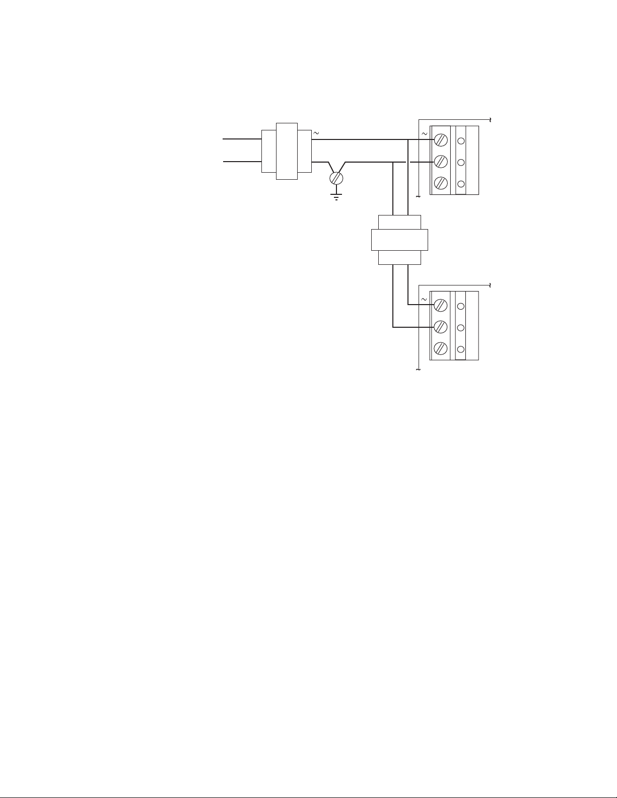
If circumstances require the use of a grounded transformer with a full-wave
and a half-wave device on a network, one possible solution may be the use of an
isolation transformer. The example shown in
Illustration 7 below, shows a single
XEE-6000 series transformer and a 24 VAC isolation transformer. (Be sure the
transformer is rated to handle the extra load—the total nominal load on a
transformer should be no more than 80% of the transformer’s rated value.) An
isolation transformer could also be used between a transformer and a single
device.
120 VAC
Common
AN0604D Revision B
1–19
Page 6
Tips for connecting 24-volt power
Connecting to controllers
KMC Controls
KMC
XEE6000
Series
Transformer
24 VAC120 VAC
24 VAC
24 VAC
Device A
Isolation
Transformer
Device B
Illustration 7 Powering a full-wave and a half-wave device from a grounded
transformer
Grounded transformer secondaries may also become a source of a network
ground loop. A ground loop occurs in a network when a small voltage potential
exists between two or more “ground” connections. This potential introduces an
unwanted current in a signal path, adding noise to the network and possibly even
damaging equipment. Symptoms of ground loops in KMC controller networks
may include one or more of the following network communication problems:
1–20
◆ Misreadings of inputs.
◆ Panels drop off the network.
◆ Multiple attempts required to open data screens.
◆ Unable to pass network points.
◆ Network bulbs illuminate.
Good network planning and wiring practices will avoid most problems with
ground loops and save considerable time and expense. To avoid ground loops,
take care to provide only one electrical path to ground and follow good wiring
practices.
AN0604D Revision B
Page 7
Digital Designer’s Guide
Calculating
transformer size
Tips for connecting 24-volt power
Calculating transformer size
An inadequately sized transformer may result in erratic network problems or
controller failure. The proper method to choose the correct size for a transformer
is calculate the total VA load and then choose a transformer with a rating 25%
higher than the total load. For example, three controllers, each rated at 10 VA can
be powered from a transformer rated for 40 VA loads.
Example:
10 VA + 10 VA + 10 VA = 30 VA
30VA x 1.25 = 40 VA
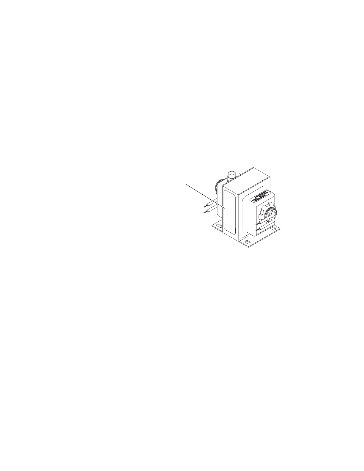
The VA rating is available from the transformer manufacturer and is usually
located on the nameplate.
Nameplate with
VA rating
Illustration 8 Typical nameplate with VA rating
AN0604D Revision B
1–21
Page 8

Tips for connecting 24-volt power
Calculating voltage drop
Calculating voltage
drop
Inadequate voltage caused by voltage drop may result in erratic network
problems or controller failure. Voltage drop occurs when power flows along a
length of wire. To minimize the effects of voltage drop, connect transformers as
close to their connected controllers as possible. The size of the connected load and
the gauge of the connecting wire has a significant effect on an acceptable distance
between the transformer and the controller.
Use the following formula to calculate voltage drop based on the length and size
of wire and the load presented by a controller. Limit the voltage drop at each
controller to no more than 5% or 1.2 volts AC.
Example:
KMC Controls
Voltage drop = Amps x (length of circuit in ft) x 2 x (ohms per 1000 ft) / 1000
= I x L x 2* x R / 1000
Table 1 Wire resistance
Wire Size–AWG, stranded Ohms / 1000 ft (at 77°F)
22 16.46
20 10.35
18 6.512
16 4.095
14 2.576
12 1.620
1–22
AN0604D Revision B
 Loading...