

Page 1
3/4" & 1" 3-Way Diverting Electronic Control Valves
Installation Guide
Required Tools
• digital voltmeter
• small screwdriver
• 2 wrenches
Mounting
Valves are sized to meet the system demand and may
be smaller than the supply lines.
1. Clean the lines upstream from the valve. Remove
any debris > .06" (.15 mm)
2. Install as close as possible to the coil in a vertical
position (actuator over the valve).
VEP–3420, 3421 Series
CAUTION: Mount valve with the actuator in the
upright position, or at most a 45° angle, to prevent
condensation collecting in the actuator housing.
3. Align system flow with arrow on valve.
4. The MPT unions are not provided and must be
ordered separately.
3/4" valves Order: Three HMO–5026s
1" valves Order: Three HMO–5027s
5. Seal valves with approved valve sealant
6. Allow a minimum clearance of 1-1/2 " (38mm)
between the top of the actuator and the nearest
obstruction. Allow sufficient side clearance for
servicing the valve.
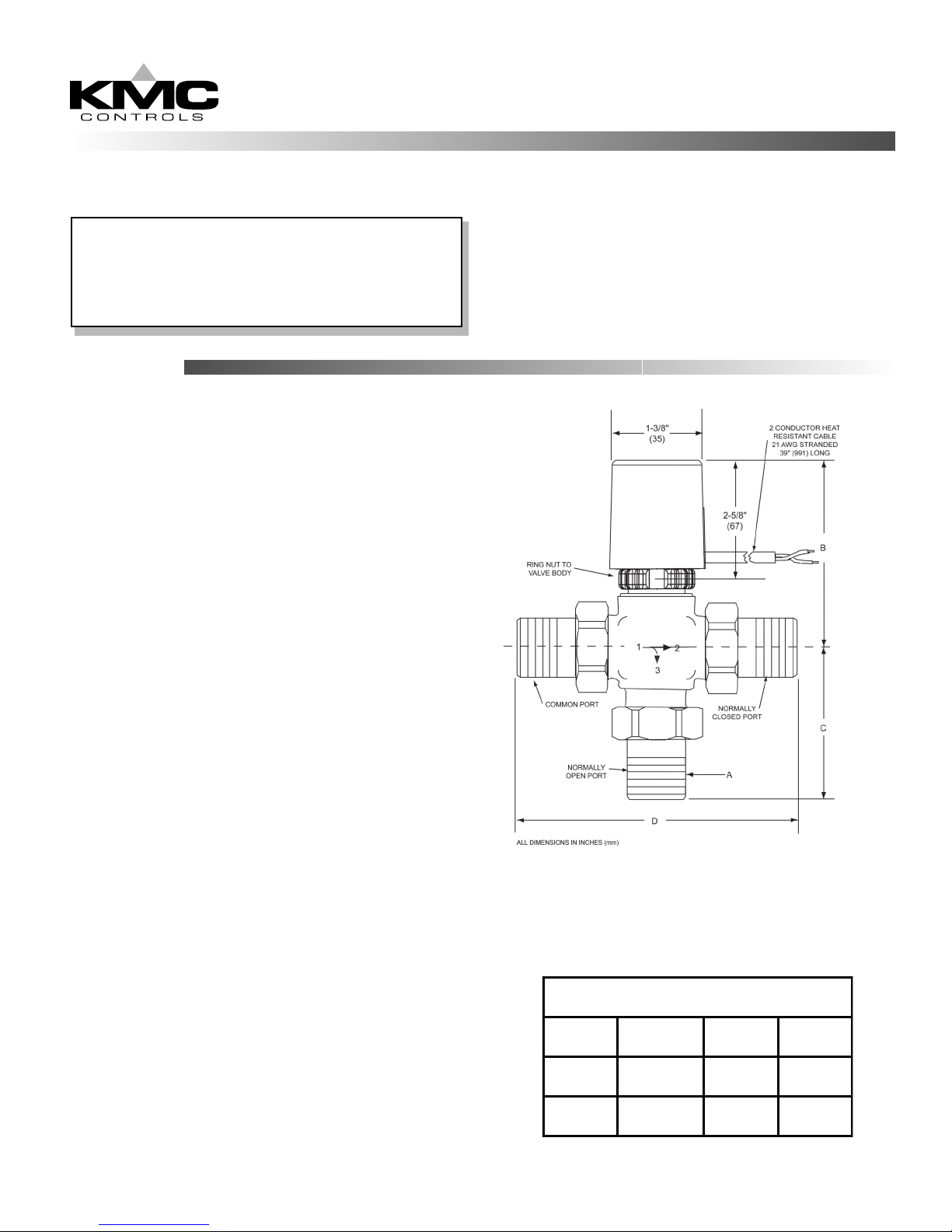
NOTE: Models do not include
HMO–5026/5027 MPT unions as
shown. Order separately.
DIMENSION REFERENCE
ABCD
3/4" MPT 3 13/16" (97) 2 3/4" (70) 5 1/8" (130)
1" MPT 4 1/16" (103) 3 1/8" (79) 5 7/8" (149)
Page 2
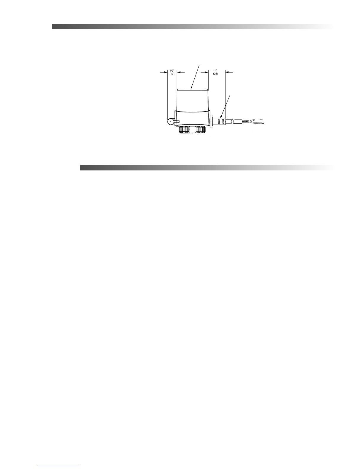
Wiring
Valves may be connected with 3/8" flexible conduit using a HMO–4530 adaptor (not included).
The VEP–3420/33421 series come with a 2 conductor, 18 AWG, heat resistant cable. The actuators are wired
for normally closed condition.
• Blue - neutral
• Brown - hot
Maintenance
No routine maintenance is required. Each component is designed for dependable, long term reliability and
performance. Careful installation will ensure long term performance. Limit field repairs to replacement of
the complete bonnet assembly or valve disc.
VEP VALVE
TOP
HMO-4530
ADAPTER FOR
3/8" FLEXIBLE
CONDUIT
KMC Controls
P.O. Box 497
19476 Industrial Drive
New Paris, IN 46553
U.S.A.
TEL: 574.831.5250
FAX: 574.831.5252
E-mail: info@kmccontrols.com
063-019-01C
 Loading...