

Page 1
Installation Guide
E/I–P Transducer
XEC-3001/3002/3004
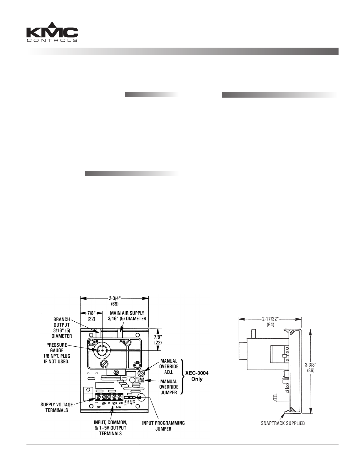
(Snap Track) Mounting
The transducers may be mounted in any position.
1. Carefully remove the circuit board from the Snap
Track.
2. Mount the track in the desired location.
3. Replace board in the track. Do not slide or ex the
circuit board while replacing.
Connections
A clean, dry, oil-free main air supply is required for
proper operation. An internal, non-replaceable lter
is used. If air supply contamination is suspected, use
an external HFO-0006 in-line lter.
The gauge port will accept a 1/8" male NPT pressure
gauge. This allows direct reading of the pressure
output. This port must be plugged if a pressure
gauge is not required.
1. Connect the 20 psi main air to the “M” port.
2. Connect the “B” port to the controlled device
(damper or valve actuator).
Wiring
1. Connect the power.
a. 24 VAC (+20%/–15%, Class 2 Only, 1 VA):
• Transformer phase lead to “~” (phase).
• Neutral lead to “GND” (common).
b. 24 VDC (+66%/–8%, 50 mA):
• Positive to “~” (phase).
• Negative to “GND.”
NOTE: Any other device connected to this
(Class 2 only) transformer must use the
same common. If you are not sure of the
other device’s polarity, use a separate
transformer. If the shared device is a coil,
use a spike-snubbing device across the coil
to prevent possible malfunctions.
2. Position Input Program Jumper to 1–5 VDC, 2–10
VDC, or 4–20 mA.
3. Connect the input signal wiring, positive to “IN”
and negative to “GND.”
4. Connect the output feedback signal (if required)
positive to “OUT 1–5” and negative to “GND.”
XEC-3001/3002/3004 1 Installation Guide
Page 2
Adjustments
Maintenance
Manual Override (XEC-3004 Only)
1. Move the “MAN/AUTO” jumper from “AUTO”
to “MAN.” (See the illustration on page 1.)
2. Adjust the potentiometer for desired output by
observing gauge or the 1–5 VDC output signal.
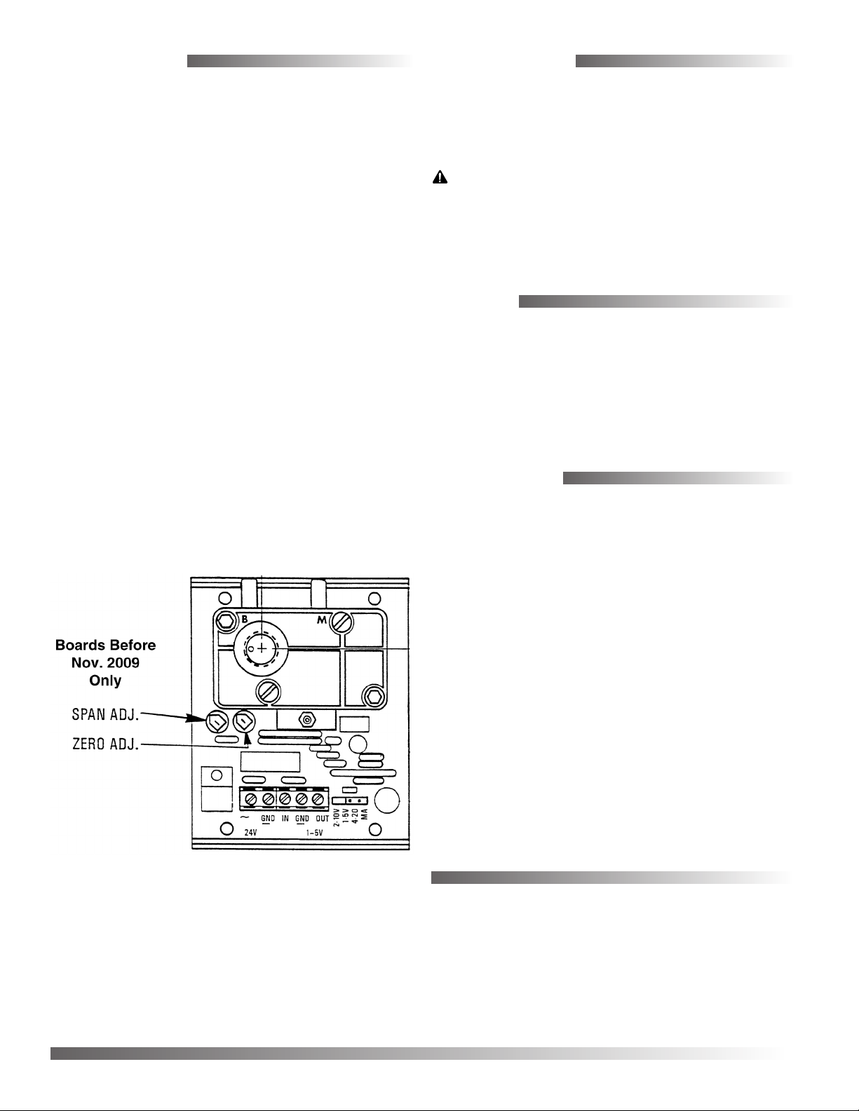
Span and Zero
The “Span and “Zero” adjustments are factory-set
and should never need adjusting. On boards manufactured before Nov. 2009 (only), this calibration may
be adjusted slightly as follows:
1. Disconnect the main air.
2. Adjust the “ZERO” potentiometer to 0.1 VDC
feedback output.
3. Reconnect the main air.
4. Apply an input voltage of 5.1 or 10.2 VDC or
input current of 20.4 mA.
5. Adjust the “SPAN” potentiometer for 15 psi
branch output pressure.
No routine maintenance is required. Each component is designed for dependable, long-term reliability, and performance. Careful installation will also
ensure long-term reliability and performance.
CAUTION
Pneumatic devices must be supplied with clean, dry
control air. Any other medium (e.g., oil or moisture
contamination) will cause the device to fail.
Models
XEC-3001 Module only
XEC-3002 Module mounted in an HCO-
1008 enclosure (not shown)
XEC-3004 Module only with manual over-
ride
Accessories
6. Apply an input voltage of 3 or 6 VDC or input
current of 12 mA.
7. Readjust the “ZERO” potentiometer for 9 psi.
HCO-1008 Enclosure (for XEC-3001/3004)
HFO-0006 In-line air lter
ICI-1005 2", 0–30 psi gauge
For other pneumatic accessories, such as connectors,
tubing, ings, lters, and gauges, see the Compressed Air Accessories section in the KMC Controls
Catalog (SP-071).
KMC Controls, Inc.
19476 Industrial Drive
New Paris, IN 46553
574.831.5250
www.kmccontrols.com
info@kmccontrols.com
XEC-3001/3002/3004 2 Installation Guide
© 2013 KMC Controls, Inc. 871-019-01J
 Loading...