

Page 1
C
2-Way, Flanged, Control Ball Valves
Installation Guide
VEB-53 Series
Mounting
1. Clean the lines upstream from the valve. Remove
any debris (welding slag, pipe scale, or other
contaminants) larger than 1/16 inch (1.6 mm).
NOTE: If the system experiences large amounts
of debris, steps should be taken to keep
the system clean, such as 20 mesh strainer
installed upstream of the valve.
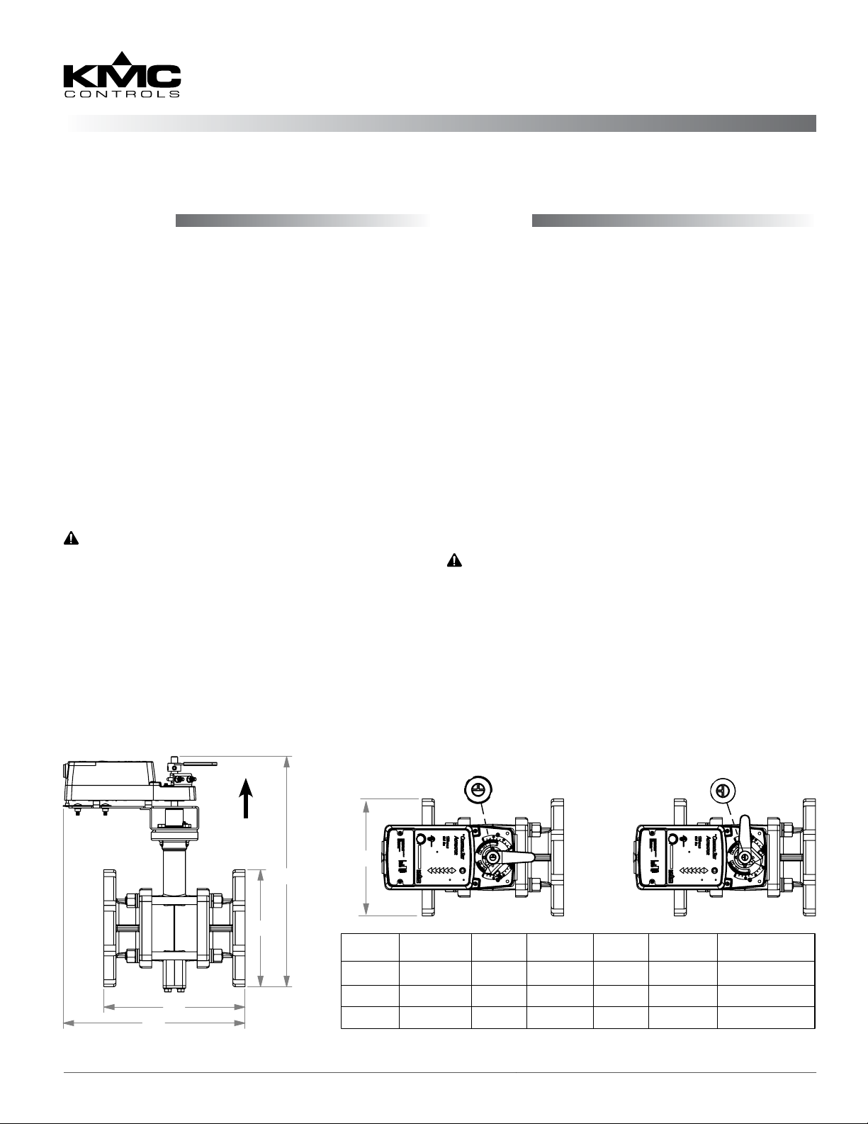
2. Align the valve assembly according to the system
ow requirements (see the illustration below).
3. The valve may be mounted on either vertical or
horizontal pipe lines. On horizontal lines, mount
the valve so the actuator is positioned upright and
over the valve. (Leave sucient room on all sides
to service the actuator and valve.)
CAUTION
To prevent condensation from dripping onto the
actuator housing on horizontal lines, mount the
valve with the actuator in the upright position or, at
most, at a 45° angle.
4. Install approved ange gaskets (not supplied by
KMC Controls) and bolt the valve to the pipes.
5. Eliminate air from the system to keep the valves
full of uid during operation.
Wiring
Wiring is dependent on the type of actuator and
the desired options that are available. Consult the
actuator model label and then the relevant sections
in the MEP-7500/7800 Series Actuators Installation
Guide for detailed instructions on the applicable
wiring, feedback selector, and actuator/signal range
reset (auto-mapping) of the valve’s actuator. (See the
More Information section on the next page.)
CAUTION
Using mineral oil lubricants or other
incompatible substances in system fluids may
damage EPDM rubber seals in valves. Before
using any lubricant or additive in a water or
ethylene glycol base, consult the substance
manufacturer for compatibility with EPDM
(Ethylene Propylene Diene Monomer).
Full CW =
UP
(on horizontal
lines)
E
B
A
VEB-53 Series Valves 1 Installation Guide
D
Size
4"
5"
6"
A B
11 9 13.75 9 17.75 70
12.375 10 14.75 10 18 80
13.875 11 15.625 11 18.875 95
Valve Open
Full CCW =
C
D
E
Valve Closed
Weight
(lb.)
Page 2

Operation
After the mechanical and electrical installations
have been completed, cycle the actuator to verify
the direction of rotation for normal operation and
fail-safe if so equipped.
Maintenance
No routine maintenance is required. The motors are
permanently lubricated. Careful installation will also
ensure long term reliability and performance.
Accessories/Repair Parts
CME-7001 Single auxiliary switch, 1 SPDT
CME-7002 Dual auxiliary switch, 2 SPDT
HMO-4536 Adjustable stop kit
MEP-7xxx Replacement actuator (see label
on actuator or data sheet)
More Information
For models, specications,
and additional information,
see the VEB-53 Series Data
Sheet on the KMC web site
(www.kmccontrols.com).
For wiring, feedback/
direction selectors, actuator/signal range reset
(auto-mapping), and other
information, see the MEP-
7500/7800 Series Installation Guide.
For actuator specications
and other information, see
the MEP-7500/7800 Series
Data Sheet.
For accessories, troubleshooting, and other
information, see the MEP-
7500/7800 Series Application Guide.
KMC Controls, Inc.
19476 Industrial Drive
New Paris, IN 46553
574.831.5250
www.kmccontrols.com
info@kmccontrols.com
VEB-53 Series Valves 2 Installation Guide© 2013 KMC Controls, Inc. 050-019-62B
 Loading...