

Page 1
Description
Valid late 2004 into 2008—
see Rev. C of this data
sheet for information on the
new case and board.
The KMC TPE–1483 series of pressure transducers
incorporates a Wet / Wet differential pressure
transmitter featuring low hysteresis, excellent
repeatability, and long-term stability.
Up to four field-selectable input ranges are available
in most models. The field selectable feature
provides a single model that can be configured to
cover all the input pressure ranges for any given
application.
Three output ranges are field selectable, 4 to 20mA,
0 to 5 VDC, and 0 to 10 VDC. The output signal is
factory calibrated and temperature compensated
for the highest start-up accuracy.
TPE–1483 Series
Pressure Transducer
The TPE–1483 can be powered from either a 24
VAC nominal or 12 to 30 VDC power source.
TPE–1483 incorporates a rugged NEMA 4
enclosure.
Features
◆ Push-button and remote zeroing terminal
◆ Uni-directional or bi-directional pressure range
selection switch
◆ High / low port swap switch to solve incorrect
plumbing for differential
◆ Normal or slow surge damping switch to
prevent false alarms and reduce noise
◆ Output polarity reverse switch
Models
The following models are available
TPE–1483–1 0 to 5/10/25/50 psig/d
TPE–1483–2 0 to 10/20/50/100 psig/d
TPE–1483–3 0 to 50/100/250/500 psig/d
Application
KMC TPE–1483 Pressure Transducers are suited for
any application requiring a reliable pressure
monitor providing a dependable conditioned and
compensated signal output.
The TPE–1483 may be used with any liquid or gas
that is compatible with 17–4 PH stainless steel.
DO NOT USE for these applications:
◆ Oxygen service
◆ Explosive/hazardous environments
◆ Flammable or combustible materials
Specifications and design subject to change without notice.
Page 2
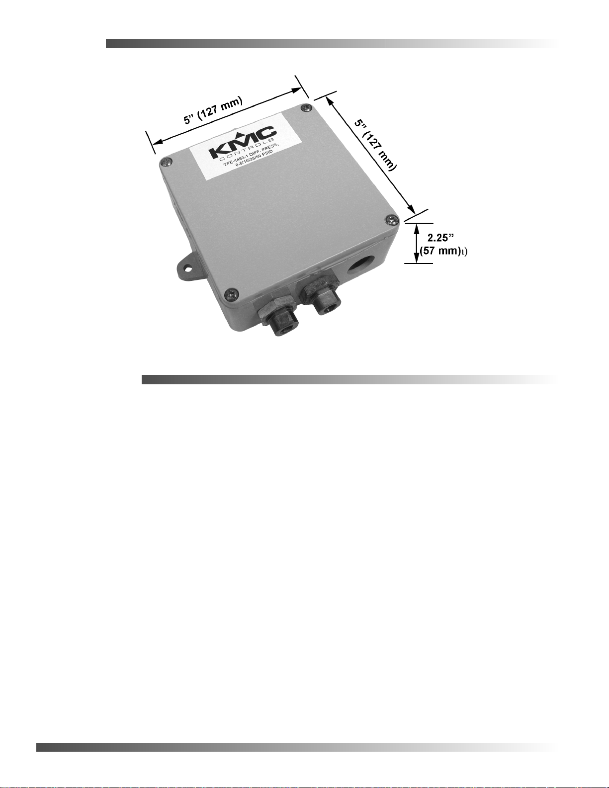
Enclosure
Specifications
Media compatibility
17–4 PH stainless steel
Supply Voltage 24 VAC or 15 to 30 VDC
Supply Current 35 mA, maximum @ 24VDC
Output Signal 4 to 20mA, 0 to 5 or 0 to 10
VDC, field selectable
Pressure Ranges Field selectable:
TPE–1483–1 0 to 5/10/25/50 psig/d
TPE–1483–2 0 to 10/20/50/100 psig/d
TPE–1483–3 0 to 50/100/250/500 psig/d
Proof Pressure Max. 2X F.S. range
Burst Pressure Max. 5X F.S. range
Accuracy ±1% F.S. combined linearity,
hysteresis, and repeatability.
Range 4 accuracy ±2% F.S.
Pressure cycles > 100 million
Surge Damping normal 4-second averaging,
slow 8-second averaging,
switch selectable
Sensor Operating Range -40° to 220°F (-40° to
105°C)
Temperature Compensation Error
32° to 130°F (0° to 55°C)
Long term stability±0.25% typical (1 year)
Zero Adjust pushbutton auto-zero and
digital input
Operating Environment
32° to 122°F (0° to 50°C), 10
to 90% RH, non-condensing
Fittings 1/8" NPT female
Enclosure 5" x 5" x 2.25" (127mm x
127mm x 57mm);
IP 54 (NEMA 4)
Shock 100G, 11 mSec, 1/2 sine
Vibration 20G peak 20 to 2400 Hz
Weight 1.33 lbs. (.60 kg)
KMC Controls, Inc.
19476 Industrial Drive
New Paris, IN 46553
574.831.5250
www.kmccontrols.com
© 2005 KMC Controls Inc. 717-035-18B
Page 3

Wet-Wet Differential Pressure Transducer
Valid late 2004 into 2008—see Rev. A of this installation guide for information on the new case and board.
Installation Guide
Mounting
Avoid locations with severe vibrations or excessive
moisture. The enclosure has a standard ½" conduit
opening and may be installed with either a conduit
coupler or a cable gland type fitting.
1. Mount on a vertical surface with the pressure
port and cable entrance on the bottom.
2. Use screws in the tab holes to fasten the
assembly to the mounting surface.
3. Ensure there is enough space around the unit to
make the pressure and electrical connections.
TPE-1483 Series
WARNING:
Do not use in explosive or hazardous environments, with combustible or flammable gasses, as a safety or
emergency stop device, or in any other application where failure of the product could result in personal
injury.
!CAUTION:
Use electrostatic discharge precautions during installation and do not exceed device ratings.
Plumbing
1. Use an appropriately rated pressure tubing for connections.
2. Arrange the tubing to minimize stress on the connections.
3. Do not allow debris to fall into the pressure ports, contamination can damage the sensor.
Page 4

Wiring
Use 22 AWG shielded wiring for all connections. Do not locate device wires in the same conduit as
wiring supplying inductive loads.
1. Connect the positive DC voltage or the hot side of the AC voltage to the terminal marked PWR.
2. Connect the power supply common to the terminal marked COM. The device is reverse voltage
protected and will not operate if connected backwards.
The analog output signal is available on the OUT terminal. This signal is jumper selectable for either
voltage or 4 to 20 mA output. In voltage mode, either 0 to 5 or 0 to 10 VDC can also be selected.
The remote zero feature may be used by wiring a dry-contact (relay only) digital output to the ZERO
terminals. Do not apply voltage to the ZERO terminals.
Set-Up
CONFIGURATION
Push-on jumpers and switches are used to select the output signal type, the input pressure
range, and several features. The device is factory configured to operate in the 4 to 20 mA output
mode but can be changed to voltage mode by moving the two jumpers from the positions
marked 'Current' to the positions marked 'Voltage'.
NOTE: Output jumpers can only be changed while the power is removed.
CAUTION: Always note the current jumper position before moving them to the new
position. If the jumpers are rotated 90 degrees and installed incorrectly the
product will not work and damage may occur.
Page 5

Set-Up Continued
JUMPER SETTINGS
Refer to the detailed drawing for pin location, the letter
designations do not appear on the actual board.
♦ 0 to 5 VDC signal Connect A to B
♦ 0 1 to 10 VDC signal Connect B to C
♦ Voltage signal Connect G to H
♦ Current Signal Connect H to I
♦ For Backlight Connect J to K
♦ No Backlight Connect K to L
RANGE
PRESSURE RANGE
MODEL 1 2 3 4
1483-1 50 PSI 20 PSI 10 PSI 5 PSI
1483-2 100 PSI 50 PSI 20 PSI 10 PSI
1483-3 500 PSI 250 PSI 100 PSI 50 PSI
NOTE: Range and Options switches can be changed while the unit is operating.
BIDIRECTIONAL
This switch changes the range from “0 to full scale differential pressure” to “minus full scale
to plus full scale differential pressure”. The analog output will read ½ when the differential
pressure is zero.
PORT SWAP
Reverses the polarity of the pressure ports. It makes the HIGH port “low” and the LOW port
“high”. This is useful to correct plumbing errors.
SLOW DAMPING
The switch provides an 8-second averaging for surge dampening (normally it is 4-seconds).
OUTPUT REVERSE
Reverses the output signal polarity. In reverse mode the analog output is maximum when the
pressure differential is zero and decreases as pressure increases.
Page 6

Set-Up Continued.
OPERATION
For normal operation such as 0 to 100 PSI, the pressure applied to the High port must be higher than the
pressure applied to the Low port. If the pressure connection is reversed then the transmitter will always
output 4 mA or 0 V.
If the Low port is left open to ambient pressure, then the High port is used to measure a positive pressure
and 0 PSI = 4 mA and 100 PSI = 20 mA.
For bidirectional operation such as +/-100 PSI, the pressure applied to the High port should be higher than
the pressure applied to the Low port for a positive output response.
Negative pressure is indicated if the High pressure is less than the Low pressure. In this case –100 PSI = 4
mA and +100 PSI = 20 mA. Since the transmitter is linear 0 PSI = 12 mA.
CALIBRATION
With both ports open to the ambient pressure or equalized at 0 pressure:
1. Press and hold the auto-zero button or provide contact closure on the ZERO terminals for at least 3 seconds.
2. Release the button or terminals and the device will calculate and store the new zero point.
NOTE: To protect the unit from accidental zeroing this feature is enabled only when the detected pressure
on both ports is less than 5% of the full range.
It is not recommended that the span calibration be performed in the field unless a high quality
calibrator is available.
Maintenance
No routine maintenance is required. Each component is designed for dependable, long term reliability and
performance. Careful installation will also ensure long term reliability and performance.
KMC Controls
P.O. Box 497
19476 Industrial Drive
New Paris, IN 46553
U.S.A.
TEL: 574.831.5250
FAX: 574.831.5252
E-mail: info@kmccontrols.com
717-019-06
 Loading...