

Page 1
STE-9000 Series NetSensor
Installation Guide
Complete the following steps to mount a KMC
Conquest STE-9000 Series Digital NetSensor
and connect it to a Conquest BAC-59xx/9xxx
Controller.
STE-90xx/93xx STE-92xx/95xx
with Motion Sensor
NOTE: See the Conquest NetSensors STE-
9000 Series Digital Room Sensors
data sheet and the Conquest Selection
Guide at kmccontrols.com for
specications and other information.
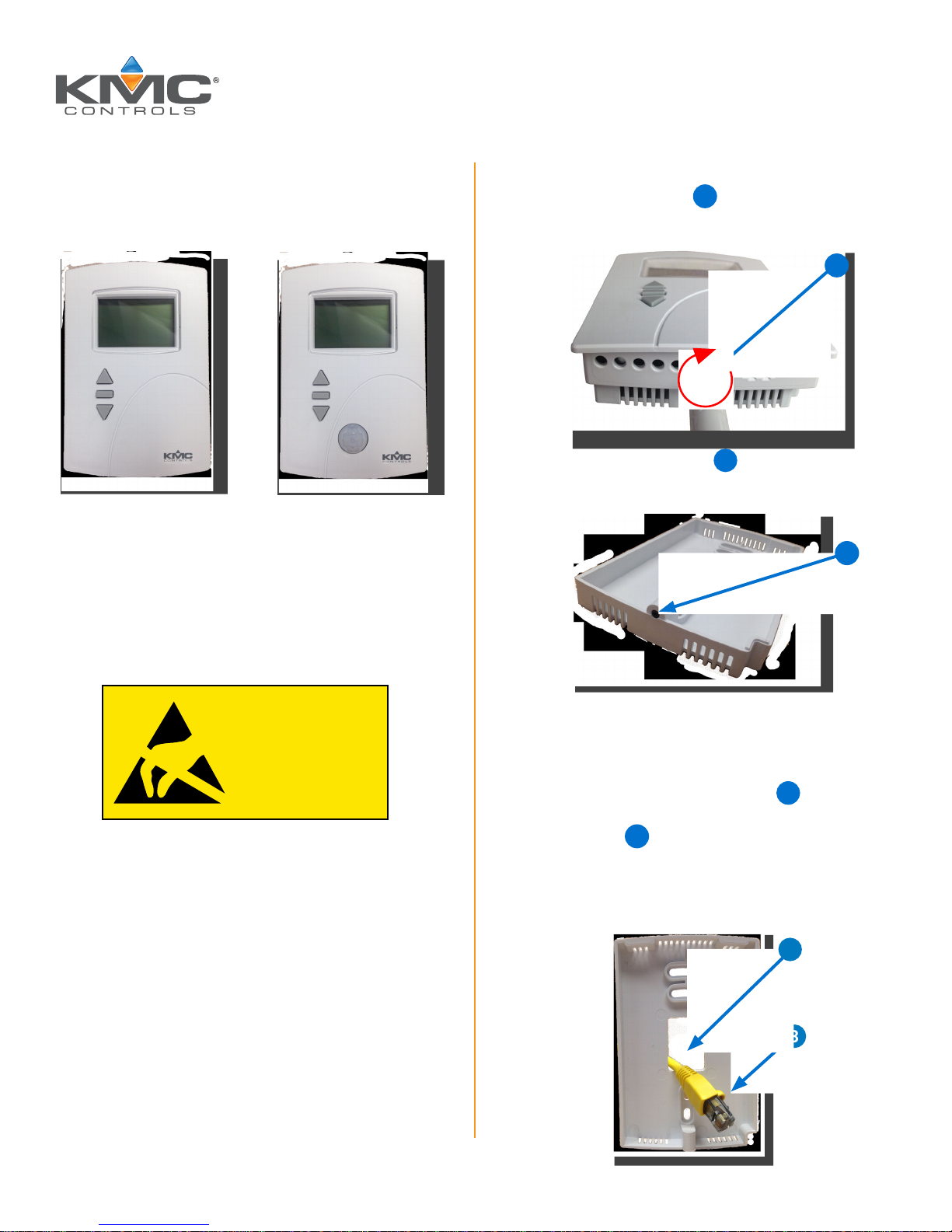
REMOVE BACKPLATE
1. Turn the hex screw 1 clockwise into the
sensor until the screw clears the cover.
1
NOTE: The hex screw 2 should remain in the
backplate.
2
NOTICE
OBSERVE PRECAUTIONS
FOR HANDLING
ELECTROSTATIC
SENSITIVE DEVICES
SELECT MOUNTING LOCATION
See the Room Sensor and Thermostat Mounting
Location and Maintenance Application Guide for
cautions, troubleshooting, and best practices.
NOTE: Complete rough-in-wiring at each
location before installing a sensor.
2. Pull the cover off the backplate.
CONNECT ETHERNET CABLE
3. Feed the Ethernet patch cable 3 from the
Conquest controller through the center of the
backplate
NOTE: The Ethernet patch cable should be a
maximum of 150 feet (45 meters).
.
4
4
3
KMC Controls, 19476 Industrial Drive, New Paris, IN 46553 / 877.444.5622 / Fax: 574.831.5252 / www.kmccontrols.com
Page 2
4. Mount the backplate on an electrical box using
the provided screws.
NOTE: If additional thermal insulation is
needed, install the optional HPO-9002
gasket before installing the backplate.
For more information, see the Room
Sensor and Thermostat Mounting
Location and Maintenance
Application Guide.
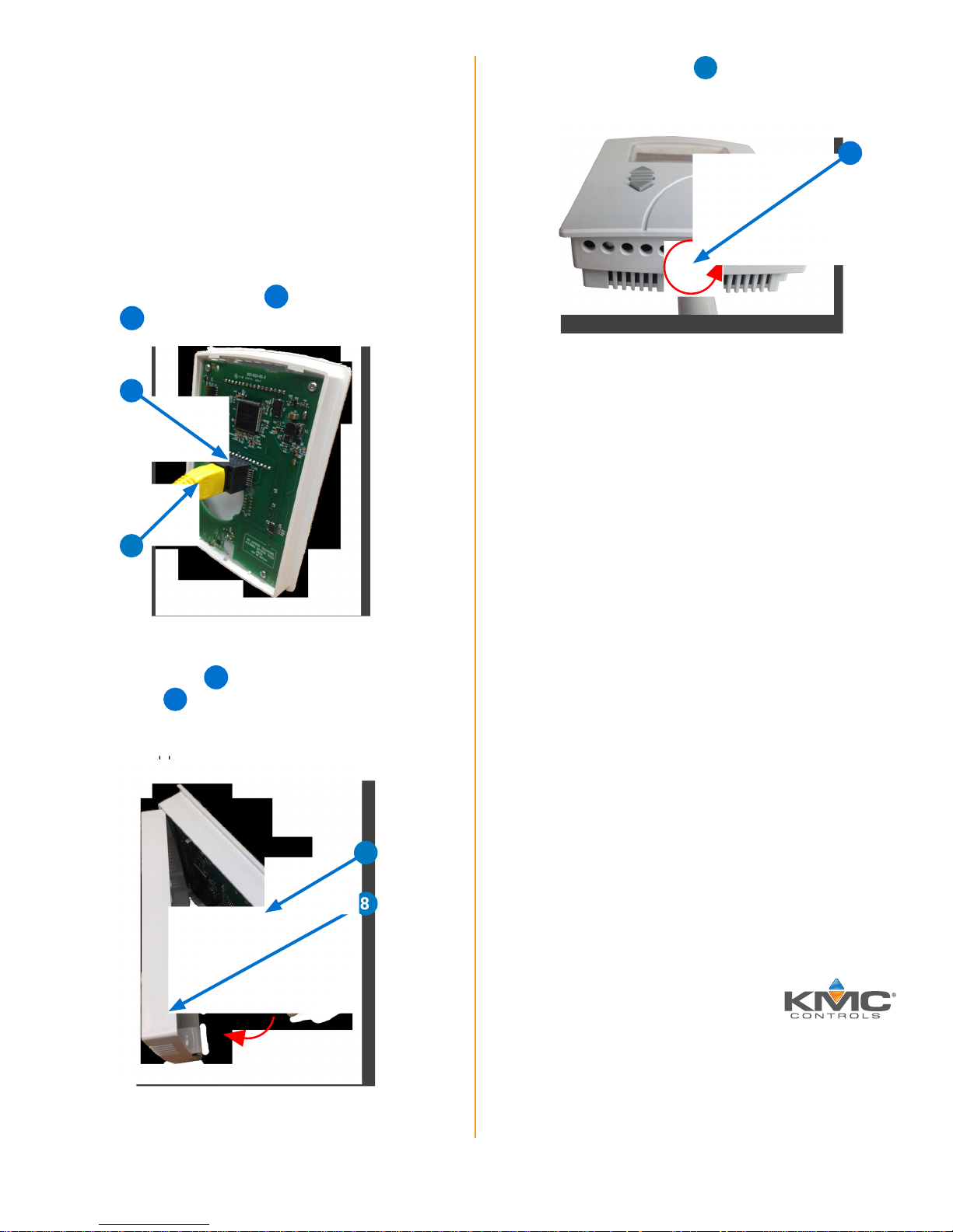
7. Turn the hex screw 9 counterclockwise until
it engages the cover.
9
5. Plug the Ethernet cable
jack
of the sensor.
6
into the modular
5
6
5
INSTALL SENSOR COVER
6. Place the cover 7 over the top of the
backplate
NOTE: Be careful not to pinch the Ethernet
cable.
and swing it down.
8
OPERATE
The STE-9000 Series NetSensor becomes
operational after it is connected to a powered
Conquest controller.
NOTE: To change setpoints or conguration,
see the KMC Conquest Controller
Application Guide.
NOTE: For continued maximum NetSensor
efciency, see the maintenance section
in the Room Sensor and Thermostat
Mounting Location and Maintenance
Application Guide.
IMPORTANT NOTICES
The material in this document is for information
purposes only. The contents and the product it
describes are subject to change without notice.
© 2017 KMC Controls, Inc. Specifications and design subject to change without notice 923-019-01D
KMC Controls, Inc. makes no representations or
warranties with respect to this document. In no
7
event shall KMC Controls, Inc. be liable for any
damages, direct, or incidental, arising out of or
8
related to the use of this document.
The KMC logo is a registered trademark of KMC
Controls, Inc. All rights reserved.
TEL: 574.831.5250
FAX: 574.831.5252
e-mail: info@kmccontrols.com
 Loading...