

Page 1
Mounting
Gauge Pressure Transducers
TPE-1464 Series
Installation Guide
NOTE: This document is for units available start-
ing in late 2008. See the original installation
guide available on the KMC web site for installation and conguration information on
older units with a dierent case and board.
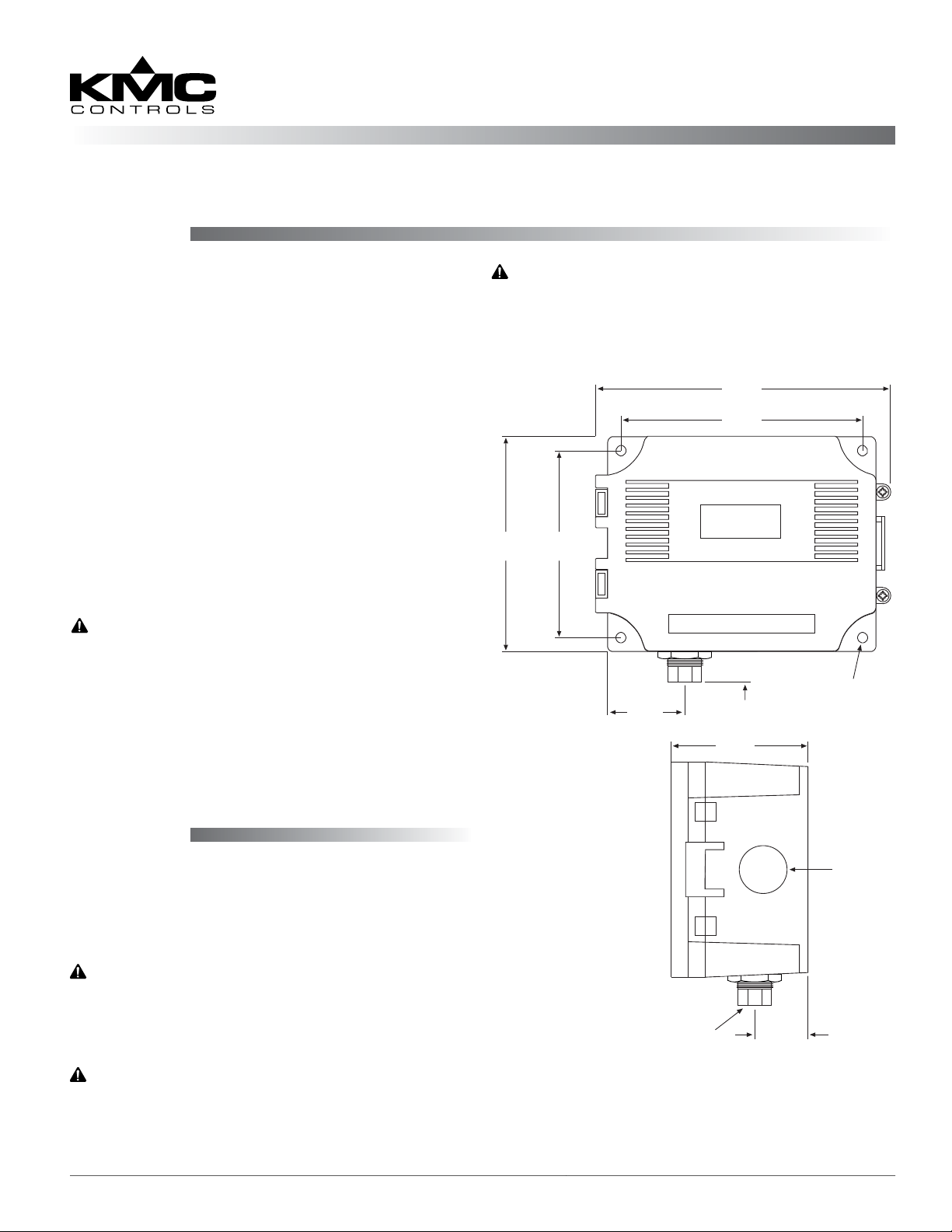
Avoid locations with severe vibrations or excessive
moisture. The enclosure has a standard 1/2" conduit
opening and may be installed with either a conduit
coupler or a cable gland type ing.
1. Mount on a vertical surface with the pressure
ports on the boom.
2. Use screws in the tab holes to fasten the assembly
to the mounting surface.
3. Ensure there is enough space around the unit to
make the pressure and electrical connections.
WARNING
Do not use:
• In an explosive or hazardous environment.
• With combustible or flammable gasses.
• As a safety or emergency stop device.
• In any other application where failure of the
product could result in personal injury.
CAUTION
Use electrostatic discharge precautions during
installation.
145 mm
5.7"
114.3 mm
4.5"
3.95"
88.9 mm
3.5"
34.93 mm
1.375"
19 mm
0.75"
64 mm
2.5"
100 mm
Mounting Holes
(X4) Ø 0.200”
Plumbing
1. Use appropriately rated pressure tubing for the
1/8" NPT female connection.
2. Arrange the tubing to minimize stress on the
connections.
CAUTION
Ensure that the maximum individual port
pressure does not exceed the maximum
pressure range of the unit.
1/8” NPT Female
25.4 mm
1"
CAUTION
Do not allow debris to get into the pressure
ports since contamination can damage the
sensor.
TPE-1464 Series Gauge Pressure Transducers 1 Installation Guide
Ø 0.850”
Page 2
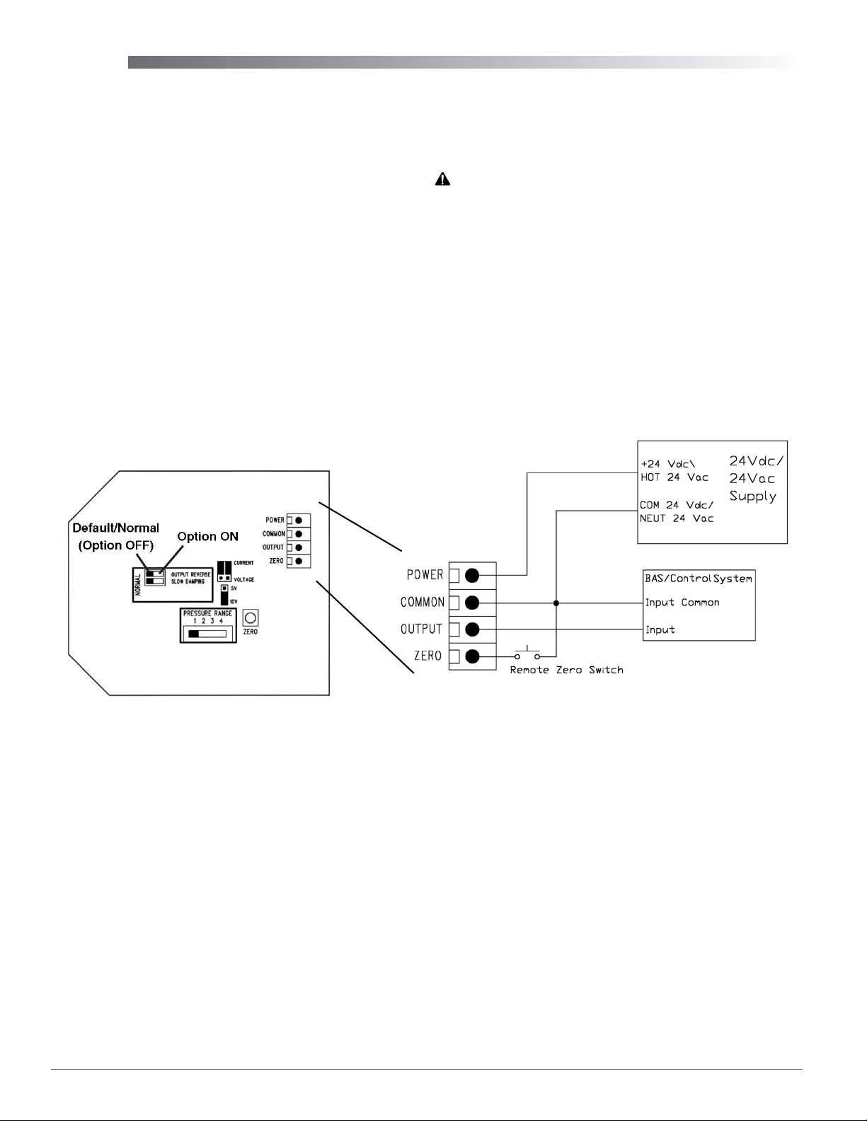
Wiring
This device is a 3-wire sourcing type transmier.
Use 22 AWG shielded wiring for all connections.
Do not locate device wires in the same conduit as
wiring supplying inductive loads (such as motors).
Disconnect the power supply before making any
connections to prevent electrical shock or equipment
damage. Make all connections in accordance with
national and local electrical codes.
1. Connect the positive DC voltage or the hot side of
the AC voltage to the terminal marked PWR.
2. Connect the power supply common to the
terminal marked COM. The unit is reverse-
voltage protected and will not operate if
connected backwards.
The analog output signal is available on the OUT
terminal. This signal is jumper selectable for either
voltage or 4 to 20 mA output. In voltage mode, either
0 to 5 or 0 to 10 VDC can also be selected.
CAUTION
Do not connect power to the OUT terminal
because the device will be damaged.
The remote zero feature may be used by wiring a
dry-contact (relay only) digital output to the ZERO
terminals. Do not apply voltage to the ZERO termi-
nals.
NOTE: This is an active device. Turn O the
relevant input pull-up resistor selector
switches on KMDigital and BACnet
controllers.
TPE-1464 Series Gauge Pressure Transducers 2 Installation Guide
Page 3

Set-Up
Configuration
Jumpers and switches are used to select the output
signal type, the input pressure range, and several
options. The device is factory congured to operate
in the 4 to 20 mA output mode but can be changed to
voltage mode by moving the two jumpers from the
CURRENT positions to the VOLTAGE positions.
CAUTION
Change the output jumper positions only while the
power is removed.
Always note the current jumper position before
moving them to the new position. If the jumpers
are rotated 90 degrees and installed incorrectly
the product will not work and damage may occur.
Jumper Settings
For voltage/current/range selection, see the illustration for jumper seings.
4–20 mA output 0–10 VDC output 0–5 VDC output
JUMPER SETTINGS
Output Reverse
This switch reverses the output signal polarity. In
reverse mode the analog output is maximum when
the pressure dierential is zero and decreases as
pressure increases.
Operation
For normal operation such as 0 to 100 psi, the port is
used to measure a positive pressure and 0 psi = 4 mA
or 0 VDC and 100 psi = 20 mA or or 10 VDC (on 10 V
range).
Calibration
With the port open to the ambient pressure or
equalized at 0 pressure:
1. Press and hold the auto-zero button or provide
contact closure between the ZERO and COMMON
terminals for at least 3 seconds.
2. Release the button, and the device will calculate
and store the new zero point.
NOTE: To protect the unit from accidental zeroing
this feature is enabled only when the
detected pressure on both ports is less than
5% of the full range.
Range
NOTE: Range and Options switches can be
changed while the unit is operating, but
change the Output jumpers only with the
power removed.
Model
1464-1 100 psi 50 psi 20 psi 10 psi
1464-2 200 psi 100 psi 40 psi 20 psi
1464-3 500 psi 250 psi 100 psi 50 psi
0 to x Pressure Range (Switch Position)
1 2 3 4
Slow Damping
For surge dampening, this switch provides an
averaging period of 8 seconds instead of the default
4 seconds.
Maintenance
No routine maintenance is required. Each component is designed for dependable, long-term reliability
and performance. Careful installation will also
ensure long-term reliability and performance.
KMC Controls, Inc.
19476 Industrial Drive
New Paris, IN 46553
574.831.5250
www.kmccontrols.com
info@kmccontrols.com
TPE-1464 Series Gauge Pressure Transducers 3 Installation Guide
© 2014 KMC Controls, Inc. 717-019-03B
 Loading...