

KMC Controls STE-6010, STE-6012, STE-6011, STE-6013 STE-6015, STE-6016 Application Manual
...Page 1
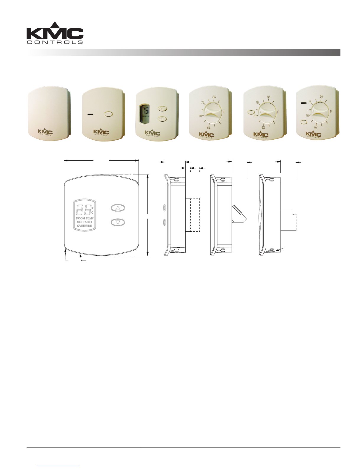
Room Temperature Sensors
2.438
2.250
R 3.094
R .187
.643
.450
STE-6012/6013/6019/6020
STE-6011
.475
max.
STE-6010/6014/6015/6016/6017/6018
Modular
RJ-45
Jack
Four-pin
EIA-485
PC Data
Port
Clamp
(Screw-type)
Terminals
Clamp
(Screw-type)
Terminals
.422 for
6019/6020
.149 for
6012/6013;
Applications Guide
STE-6000 Series
STE-6010/6011 STE-6013/6015
STE-6000 Series Overview .........................................................................................................................................2
Maintenance ..............................................................................................................................................................3
More Information ......................................................................................................................................................3
Wiring ........................................................................................................................................................................3
STE-6011 ............................................................................................................................................................. 3
STE-6013 ............................................................................................................................................................. 3
STE-6019/6020 ....................................................................................................................................................3
STE-6012 ............................................................................................................................................................. 3
STE-6010/6014/6015/6016/6017/6018 .............................................................................................................. 4
STE-6012/6016 Connection Configuration ................................................................................................................5
Overview .............................................................................................................................................................5
Controller Connection .........................................................................................................................................5
Fahrenheit/Celsius Display Selection ...................................................................................................................5
Temperature Calibration (Offset) Procedure ........................................................................................................5
Controller Configuration ............................................................................................................................................6
Overview .............................................................................................................................................................6
WinControl ..........................................................................................................................................................6
BACstage .............................................................................................................................................................9
STE-6000 Series Room Temperature Sensors 1 Applications Guide
STE-6012/6016
All dimensions are in inches
STE-6014 STE-6018/6020STE-6017/6019
Page 2

STE-6000 Series Overview
These compact, stylish, and economical room
temperature sensors are designed for use in KMC
Digital controllers or other building automation
systems. They incorporate a 10,000 ohm (@ 77°
F) thermistor for the sensing element, providing
precise, stable temperature sensing. The low prole
and durable thermostat-style cover are visually
appealing. These sensors may be surface mounted on
a hollow wall or to a 2 x 4 in. electrical box.
The STE-6000 Series is specically designed to
complement the KMC Digital controllers.
An STE-6010/6011 contains a thermistor only.
An STE-6014/6017/6019/6018/6020 includes a rotary
setpoint dial (available in degrees F or C).
An STE-6013/6015/6017/6019/6018/6020 allows selection of an override condition by pushing the buon
on the front. A green status LED (not on the STE-
6017/6019) illuminates according to the user-dened
controller conguration (e.g., during setback/setup
or during normal/override modes).
An STE-6012/6016 includes an LCD display for the
room temperature and setpoint. The temperature
display can be toggled between Fahrenheit and
Celsius scales. The setpoint is adjustable via the
up and down arrow buons on the front panel. If
the system is in normal/override mode, pressing a
buon will raise or lower the setpoint. When either
buon is pushed, the display will toggle from room
temperature to the setpoint. When the buon is
released, the number displayed is the new setpoint,
and the display will return to room temperature aer
ten seconds. If the system is in setback/setup (for
heating/cooling) mode, pressing either buon selects
override mode.
An STE-6010/6014/6015/6016/6017/6018 includes a
four-pin EIA-485 (formerly RS-485) data port on
the cover’s underside for easy temporary computer
connection to the network. (Access with a KMD-5624
cable.)
For more specications and mounting instructions,
see the Data Sheet and the Installation Guide for
the STE-6000 series.
The following models are available:
Setpoint
Adjust
STE-
601x
Model
Number
Rotary Dial
6010-10 X X X
6011-10 X X
6013-10 X X X X
6015-10 X X X X X
6012-10 X X X X X
6016-10 X X X X X X
6014-10 ° F X X X
6014-11 ° C X X X
6017-10 ° F X X X X
6017-11 ° C X X X X
6019-10 ° F X X X
6019-11 ° C X X X
6018-10 ° F X X X X X
6018-11 ° C X X X X X
6020-10 ° F X X X X
6020-11 ° C X X X X
Other
Interface
Features
Up/Down Buttons
Override Button(s)
Connections
LCD Display
LED Status Indicator
Cable
RJ-45 Connector
Screw Clamp Terminals
EIA-485 Data Port
Temper-
ature
Output
10k Ohms Thermistor
The standard color is almond. To order in white
(minimum quantity of 250 required), add a “W” in the
place of the hyphen near the end of the model number
(e.g., STE-6012W10).
Accessories available include:
◆ HMO-6036: Universal Backplate
◆ KMD-569x: STE-6010/6014/6015/6016 to Con-
troller Cable with RJ-45 to RJ-11 Connectors (5693 = 25 ft.; -5694 = 50 ft.; -5695 = 75 ft.)
◆ KMD-5624: PC Data Port (EIA-485) Cable
◆ KMD-5576: EIA-485 to USB Communicator
0 to 5 VDC
STE-6000 Series Room Temperature Sensors 2 Applications Guide
Page 3
Maintenance
Wiring
Careful installation will also ensure long-term reliability and performance. Remove dust as necessary
from holes in top and boom. Clean with a so,
damp cloth and mild soap.
More Information
For additional specications, see the STE-6000 Data
Sheet.
For mounting information, see the STE-6000 Installation Guide.
For an additional sample application of program-
ming override timers, adapt the information in the
Application Note AN0504F Programming Override
Timers section of the the Digital Designer’s Guide
(SP-022).
For applications requiring humidity sensing, the
THE-1002/1102/1105 humidity transmiers also
include the same type of thermistor as in the STE6000 series.
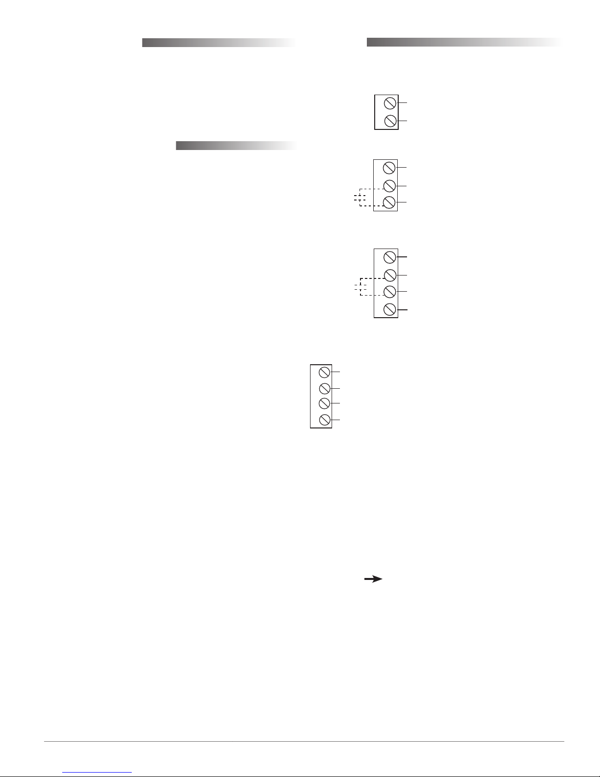
Connect wires as shown for the relevant model.
STE-6011
(Wires are
interchangeable)
Thermistor (10k Ohms)
STE-6013
10 VDC LED Supply (from Controller)
Common (Ground)
Thermistor (10k Ohms)
(Override
Button)
D
B
C
STE-6019/6020
Potentiometer
Common (Ground)
Thermistor (10k Ohms)
10 VDC LED Supply (from Controller;
for STE-6020 Only)
(Override
Button)
A
B
C
D
STE-6012
7.5 VDC (Setback/Setup) or
D
B
C
A
{
12 VDC (Normal/Override) Supply (from Controller)
{
Common (Ground)
0–5 VDC Temperature Signal and (Momentary)
{
SENSOR-ON (0 VDC) or SENSOR-OFF (> 5 VDC)
{
0–5 VDC Setpoint Signal
NOTE: In the STE-6012/6016, pressing the Down buon
momentarily sends 0 VDC to the controller for
a SENSOR-ON signal; pressing the Up buon
sends greater than 5 VDC for a SENSOR-OFF
signal. When in normal/override mode, pressing
the Down or Up buon raises or lowers the
setpoint voltage. When in setback/setup mode,
pressing either buon selects override mode.)
(For the STE-6010/6014/6015/6016/6017/6018, see the
next page. )
STE-6000 Series Room Temperature Sensors 3 Applications Guide
Page 4
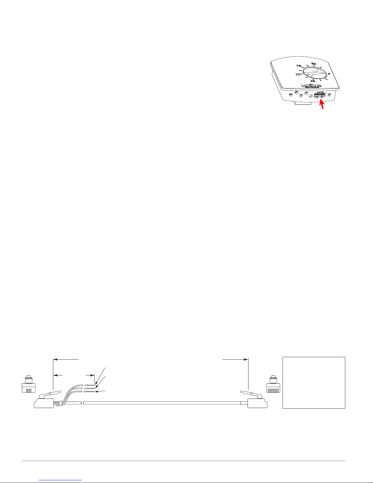
STE-6010/6014/6015/6016/6017/6018
KMD–5693 = 25 feet; KMD–5694 = 50 feet; KMD–5695 = 75 feet
1 8
Orange Wire = Thermistor Input to Controller
Orange/White Wire = Setpoint Signal Input to Controller
(for STE-6014/6016/6017/6018 only; clip or tape when not used)
12 inches
52
RJ-11 and
Wire Leads
to Controller
RJ-45
to STE
Sensor
Green Wire = Aux. Supply Voltage to STE-6015/6018
(10 VDC) or STE-6016 (7.5/12 VDC) (clip or tape when not used)
RJ-11 RJ-45 Color
(Lead) 8 Orange
7 N.C.
(Lead) 6 Green
3 5 Blue
4 4 Blue/White
5 3 Green
2 N.C.
(Lead) 1 Orange/White
(Cables crossed, 20 AWG)
Controller Connection
Connecting any of these models to a controller
requires a special cable with (on the sensor end) an
RJ-45 connector and (on the controller end) an RJ-11
connector with an additional three wires (as relevant
to the model) for controller inputs. Purchasing
preassembled cables from KMC is more cost-
eective and reliable than creating custom cables in
the eld. Use one of the following cables:
KMD-5693 = 25 .
•
KMD-5694 = 50 .
•
KMD-5695 = 75 .
•
The additional orange wire is for the thermistor
input to the controller. The additional orange/white
wire is for the STE-6014/6016/6017/6018 setpoint
signal input to the controller. The additional green
wire is for the auxiliary supply voltage of 10 VDC
to the STE-6015/6018 or 7.5/12 VDC to the STE-6016.
The STE-6016 is the only model that uses all the
wires. For the other models, clip or tape the unused
wire(s).
PC Port Connection
At the boom of an STE-
6010/6014/6015/6016/601
7/6018 case is an EIA-485
(formerly RS-485) computer port. This port provides
a temporary connection
to the digital network for
network setup or troubleshooting.
To use the port to connect to a computer, a means of
converting the EIA-485 signal to a USB or EIA-232
(formerly RS-232) signal will be needed. The exact
connection depends on the computer and the opera-
tor workstation soware. (See also the instructions
included with those devices and soware.)
For USB (to WinControl or BACstage), use a KMD-
5576 USB Communicator.
For EIA-232 to BACstage, use a third-party interface.
For EIA-232 to WinControl, use the following (or
equivalent) items:
KMD-5624 NetSensor to PC cable
•
KMD-5559 CommTalk
•
KMD-5625 adapter cable
•
To access the network through the STE’s port:
1. Connect the keyed, at end of the EIA-485 cable
to the port on the boom of the STE.
2. Connect the other end of the cable to the interface
device that converts the EIA-485 signal into an
EIA-232 or USB signal.
3. Connect the suitable cable from the interface
device to the computer’s serial or USB port. Install
any required soware and congure the port as
necessary.
STE-6000 Series Room Temperature Sensors 4 Applications Guide
Page 5

STE-6012/6016 Connection Configuration
Overview
Each STE-6012/6016 includes an
LCD display for the room temperature and setpoint, which can
be toggled between Fahrenheit
(the default) and Celsius scales.
The sensor allows a user to adjust
the setpoint via the up and down
arrow buons on the front panel. If the system is in
standard mode (12 VDC applied to terminal D or the
green wire), pressing a buon will raise or lower the
setpoint. When either buon is pushed, the display
will toggle from room temperature to the setpoint.
The setpoint will increment or decrement (a degree
with each press) depending on the buon being
pressed. When the buon is released, the number
displayed is the new setpoint, and the display will
return to room temperature aer ten seconds. If the
system is in setback/setup (for heating/cooling) mode
(7.5 VDC applied to terminal D or the green wire),
pressing either buon selects override mode.
Controller Connection
1. Press and hold either the down or up arrow
buons for at least 20 seconds. The display will
toggle from one temperature scale to the other.
2. Release the buon.
NOTE: This seing is wrien to nonvolatile
memory and will be saved even if power to
the sensor is lost.
Temperature Calibration (Offset) Procedure
NOTE: The total oset value is limited to +/– 3
degrees from the default value.
The temperature value displayed by the STE-
6012/6016 may be ne-tuned if desired by
performing the following steps. The sensor must be
in a stable location and operating at least ten minutes
before calibrating. Hold an accurate thermometer
about an inch under the unit as a reference during
this procedure.
1. Click the down arrow buon to decrement the
setpoint to its lowest value, 40° Fahrenheit or
4° Celsius, then press and hold the down arrow
buon.
For the STE-6012/6016, the controller will need signal
lines for two inputs (thermistor and setpoint), one
output (7.5/12 VDC supply), and common (ground).
Since each STE-6012/6016 has 0–5 volt DC outputs
for both the temperature and the setpoint lines,
turn o the corresponding 10,000 ohm pull-up
resistors on the controller board! Consult the
controller’s setup instructions for information on
turning o the pull-up resistors. For the other STE6000 series sensors, do not turn o the resistors on
the controller board as stated for the STE-6012/6016.
NOTE: For controller conguration instructions
for both WinControl and BACstage, see the
Controller Conguration section.
Fahrenheit/Celsius Display Selection
The STE-6012/6016 has an LCD display for showing
room temperature and setpoint. The display can be
toggled between Fahrenheit (the default) and Celsius
scales by performing the following procedure.
NOTE: Doing this erases any stored calibration
oset value (see below) and returns the
calibration to the default seing!
2. Aer holding the down arrow buon for about
ten seconds, the display will start ashing
the room temperature value and start an
approximately 15-second “exit calibration” timer.
NOTE: Entering the calibration mode erases any
previous saved oset value and will return
to the default seing.
3. While the room temperature value is ashing,
press the up or down arrow buon to modify the
room temperature value. Each press of the up or
down arrow buon will change the temperature
value by one degree.
4. The display will continue to ash for
approximately 15 seconds aer the last buon
press. Then the STE-6012/6016 will write the
modied value to memory and return to normal
operation.
NOTE: This procedure aects only the temperature
displayed on the LCD panel. It does not
aect the calibration or temperature value
in the controller. See also the WinControl
Thermistor Input controller conguration
instructions.
STE-6000 Series Room Temperature Sensors 5 Applications Guide
Page 6

Controller Configuration
Overview
For an STE-6012/6016 sensor, the controller will need
two inputs (thermistor and setpoint), one output,
and a common (ground) signal lines.
Since an STE-6012/6016 sensor has 0–5 volt outputs
for both the temperature and the setpoint lines,
turn o the corresponding 10,000 ohm pull-up
resistors on the controller board! Consult the
controller’s setup instructions for information on
turning o the pull-up resistors. For the other STE6000 series sensors, do not turn o the resistors on
the controller board as stated for the STE-6012/6016.
Controller conguration instructions are given for
both WinControl and BACstage. See the relevant
soware section.
WinControl
Thermistor Input (All)
NOTE: On the controller board, turn o the 10,000
ohm pull-up resistor (for STE-6012/6016
only).
1. In the WinControl soware main menu, select
Control > Inputs.
Setpoint Voltage Input (STE-6012/6016 only)
NOTE: On the controller board, turn o the 10,000
ohm pull-up resistor.
1. In the WinControl soware main menu, select
Control > Inputs.
2. Click Edit.
3. Type in a name in the Description eld and/or
Label eld.
4. Click Units (which opens the Congure Inputs
screen).
5. Select Type: Analog if it is not the default.
6. Select 0–5 Volts.
NOTE: The voltage will be used in the formula of
line 30 of the Control Basic sample to equal
the setpoint temperature.
7. Click OK.
8. Click End Edit.
9. Click OK.
2. Click Edit.
3. Type in a name in the Description eld (up to 20
characters) and/or Label eld (up to 8 characters).
NOTE: No two labels or descriptions in a controller
can be identical.
4. Click Units (which opens the Congure Inputs
screen).
5. Select Type: Analog if it is not the default.
6. Select Deg F (or C) KMC10K Type II.
7. Optionally, to match the STE-6012/6016 LCD
display value with the value used by the
controller, adjust the Calibration value if desired.
8. Optionally, change Format from 0 to the desired
number of temperature decimal places.
9. Optionally, change the Average to the desired
number of thermistor readings averaged before
displaying the result.
10. Click OK.
11. Click End Edit.
12. Click OK.
STE-6000 Series Room Temperature Sensors 6 Applications Guide
Page 7

Setpoint Voltage Input (STE-6014/17/18/19/20 only)
Setpoint Variable (STE-6012/14/16/17/18/19/20 only)
1. In the WinControl soware main menu, select
Control > Inputs.
2. Click Edit.
3. Type in a name in the Description eld and/or
Label eld.
4. Click Units (which opens the Congure Inputs
screen).
5. Select Type: Analog if it is not the default.
6. Select Table.
7. Click OK.
8. Click End Edit.
9. Click OK.
10. In the WinControl soware main menu, select
Control > Tables.
11. Click Unused in the rst available column.
12. Select Deg. F.
13. Click OK.
14. Enter the following values under Table x and Deg.
F:
Table x
[1 or next available number]
1 0.00 54
2 0.32 58
3 0.77 62
4 1.14 66
5 1.47 70
6 1.74 74
7 1.97 78
8 2.16 82
9 2.31 86
10 2.42 90
11 5.00 90
Deg. F
1. In the WinControl soware main menu, select
Control > Setpoint/Variables.
2. Click Edit.
3. Type in a name in the Description eld and/or
Label eld.
4. Click Units (which opens the Congure Variables
screen).
5. Select Type: Analog if it is not the default.
6. Select Degrees Fahrenheit (or Celsius).
7. Set Format to 0.
8. Click OK.
9. Click End Edit.
10. Click OK.
Override Input (STE-6012/13/15/16/17/18/19/20 only)
1. In the WinControl soware main menu, select
Control > Setpoint/Variables.
2. Click Edit.
3. Type in a name in the Description eld and/or
Label eld.
4. Click Units (which opens the Congure Variables
screen).
5. Select Type: Digital.
6. Select O/On (or No/Yes, Stop/Start, Dis/Enabled
according to preference).
7. Click OK.
8. Click End Edit.
9. Click OK.
15. Click OK.
STE-6000 Series Room Temperature Sensors 7 Applications Guide
Page 8

Supply Output (STE-6012/6016 only)
NOTE: The STE-6012/6016 is powered from the
controller output. A supply of 7.5 volts DC
puts the sensor in setback/setup mode and
12 volts puts it in normal/override mode.
1. In the WinControl soware main menu, select
Control > Output.
2. Click Edit.
3. Type in a name in the Description eld and/or
Label eld.
4. Select Units.
5. Select Type: Analog if it is not the default.
6. Select 0–10 Volts.
NOTE: This only sets the scale; the actual voltage
may go up to 12 volts DC.
7. Leave the rest of defaults.
8. Click OK.
9. Click End Edit.
10. Click OK.
Optional Control Basic (STE-6012/6016 only)
60 REM *** IN1 IS ROOM TEMP VOLTAGE FROM
SENSOR (FROM LINE 1 IN INPUT SCREEN)
***
70 REM *** VAR4 IS THE OVERRIDE (FROM
LINE 2 IN VARIABLE SCREEN) ***
80 REM *** USE BUTTON ON SENSOR TO START
OVERRIDE (VAR4) ***
90 IF SENSOR-ON( IN1 ) OR SENSOR-OFF( IN1
) THEN START VAR4
100 IF TIME-ON( VAR4 ) > 2:00:00 THEN
STOP VAR4
110 END
NOTE: For Celsius, use these lines for 10 through
30 instead.
10 REM *** SETPOINT RANGE FOR ROOM SENSOR
***
20 REM *** RANGE IS 4 - 32 DEGREES CEL-
SIUS ***
30 VAR2 = IN2 / 0.17857 + 4
1. In the WinControl soware main menu, select
Control > Control Basic.
2. Click Edit.
3. Type in a name in the Description eld and/or
Label eld.
4. Place an x in the On column.
5. Click End Edit.
6. Click once in the # column.
7. Type in program lines (see the following
example).
NOTE: This is only an example. Details need to t
the controller conguration.
10 REM *** SETPOINT RANGE FOR ROOM SENSOR
***
20 REM *** RANGE IS 40 - 90 DEGREES FAHR-
ENHEIT ***
30 VAR2 = IN2 / 0.1 + 40
40 REM *** VAR2 IS THE ROOM SETPOINT
(FROM LINE 1 IN VARIABLE SCREEN) ***
50 REM *** IN2 IS SETPOINT VOLTAGE FROM
SENSOR (FROM LINE 2 IN INPUT SCREEN)
***
8. Click Send.
9. Click OK.
10. Click Close.
11. Click OK.
NOTE: The STE-6012/6016 is powered by the
controller on terminal D or the green wire.
With 7.5 VDC applied, the sensor is in
setback/setup mode; with 12 VDC applied,
the sensor is in normal/override mode.
Pressing the Down buon momentarily
sends 0 VDC to the controller for a
SENSOR-ON signal; pressing the Up buon
sends greater than 5 VDC for a SENSOR-
OFF signal. When in normal/override
mode, pressing the Down or Up buon
raises or lowers the setpoint voltage. When
in setback/setup mode, pressing either
buon selects override mode.
NOTE: For an additional sample application
of programming override timers, adapt
the information in the Application Note
AN0504F Programming Override Timers
section of the the Digital Designer’s Guide
(SP-022).
STE-6000 Series Room Temperature Sensors 8 Applications Guide
Page 9

BACstage
Thermistor Input (All)
NOTE: On the controller board, turn o the 10,000
ohm pull-up resistor (for STE-6012/6016
only).
1. In the BACstage soware main menu, select
Objects > Inputs.
2. Click Edit.
3. Type in a name in the Description eld (up to 32
characters) and/or Label eld (up to 16 characters).
NOTE: No two labels or descriptions in a controller
can be identical.
4. Select Object Type: Analog if it is not the default.
5. Select Device Type: KMC10K Type II.
6. Select Units: °F or °C.
7. Click End Edit.
8. Click Yes for “Send Update Notication Now?”
9. In the BACstage soware main menu, select
Device > Device Tables > KMC10K Type II Table.
10. Click Edit.
11. Click Defaults (values will ll in).
12. Click End Edit.
Setpoint Voltage Input (STE-6014/17/18/19/20 only)
1. In the BACstage soware main menu, select
Objects > Inputs.
2. Click Edit.
3. Type in a name in the Description eld and/or
Label eld.
4. Select Object Type: Analog if it is not the default.
5. Select Device > Device Tables > Table x (4 or 5).
6. Select Units: °F or °C.
7. Click End Edit.
8. Click Yes for “Send Update Notication Now?”
9. In the BACstage soware main menu, select
Device > Device Tables > Table x.
10. Click Edit.
11. Enter the following values in Table x:
NOTE: In the Adobe Acrobat le of this
document, you can use the table on page
10 to copy and paste the 128 lines into the
appropriate section of the BACstage *.BAC
panel le (instead of typing in the values
from the table below).
13. Click Yes for “Send Update Notication Now?”
14. Click OK.
Setpoint Voltage Input (STE-6012/6016 only)
NOTE: On the controller board, turn o the 10,000
ohm pull-up resistor.
1. In the BACstage soware main menu, select
Objects > Inputs (if the screen was closed
previously).
2. Click Edit.
3. Type in a name in the Description eld and/or
Label eld.
4. Select Object Type: Analog if it is not the default.
5. Select Device Type: Volts 0–5.
6. Click End Edit.
7. Click Yes for “Send Update Notication Now?”
8. Click OK.
Index Value
1 54.0
2 54.3
3 54.6
4 54.9
5 55.2
6 55.5
7 55.8
8 56.1
9 56.4
10 56.7
11 57.1
12 57.4
13 57.7
14 58.1
15 58.4
STE-6000 Series Room Temperature Sensors 9 Applications Guide
Page 10

16 58.8
17 59.1
18 59.5
19 59.9
20 60.3
21 60.7
22 61.1
23 61.5
24 61.9
25 62.3
26 62.7
27 63.2
28 63.6
29 64.1
30 64.5
31 65.0
32 65.5
33 66.0
34 66.5
35 67.0
36 67.5
37 68.1
38 68.6
39 69.2
40 69.8
41 70.4
42 71.0
43 71.6
44 72.2
45 72.9
46 73.5
47 74.2
48 74.9
49 75.6
50 76.3
51 77.1
52 77.8
53 78.6
54 79.4
55 80.3
56 81.1
57 82.0
58 82.9
59 83.8
60 84.8
61 85.8
62 86.8
63 87.8
64 88.9
65 90.0
66 90.0
67 90.0
68 90.0
69 90.0
70 90.0
71 90.0
72 90.0
73 90.0
74 90.0
75 90.0
76 90.0
77 90.0
78 90.0
79 90.0
80 90.0
81 90.0
82 90.0
83 90.0
84 90.0
85 90.0
86 90.0
87 90.0
88 90.0
89 90.0
90 90.0
91 90.0
92 90.0
93 90.0
94 90.0
95 90.0
96 90.0
97 90.0
98 90.0
99 90.0
100 90.0
101 90.0
102 90.0
103 90.0
104 90.0
105 90.0
106 90.0
107 90.0
108 90.0
109 90.0
110 90.0
111 90.0
112 90.0
113 90.0
114 90.0
115 90.0
116 90.0
117 90.0
118 90.0
119 90.0
120 90.0
121 90.0
122 90.0
123 90.0
124 90.0
125 90.0
126 90.0
127 90.0
128 90.0
12. Click End Edit.
13. Click Yes for “Send Update
Notication Now?”
14. Click OK.
STE-6000 Series Room Temperature Sensors 10 Applications Guide
Page 11

Setpoint Variable (STE-6012/14/16/17/18/19/20 only)
NOTE: In the Adobe Acrobat le of this
document, you can select the table below
to copy and paste the 128 lines into the
appropriate device table section of the
BACstage *.BAC panel le.
X1=54.0
X2=54.3
X3=54.6
X4=54.9
X5=55.2
X6=55.5
X7=55.8
X8=56.1
X9=56.4
X10=56.7
X11=57.1
X12=57.4
X13=57.7
X14=58.1
X15=58.4
X16=58.8
X17=59.1
X18=59.5
X19=59.9
X20=60.3
X21=60.7
X22=61.1
X23=61.5
X24=61.9
X25=62.3
X26=62.7
X27=63.2
X28=63.6
X29=64.1
X30=64.5
X31=65.0
X32=65.5
X33=66.0
X34=66.5
X35=67.0
X36=67.5
X37=68.1
X38=68.6
X39=69.2
X40=69.8
X41=70.4
X42=71.0
X43=71.6
X44=72.2
X45=72.9
X46=73.5
X47=74.2
X48=74.9
X49=75.6
X50=76.3
X51=77.1
X52=77.8
X53=78.6
X54=79.4
X55=80.3
X56=81.1
X57=82.0
X58=82.9
X59=83.8
X60=84.8
X61=85.8
X62=86.8
X63=87.8
X64=88.9
X65=90.0
X66=90.0
X67=90.0
X68=90.0
X69=90.0
X70=90.0
X71=90.0
X72=90.0
X73=90.0
X74=90.0
X75=90.0
X76=90.0
X77=90.0
X78=90.0
X79=90.0
X80=90.0
X81=90.0
X82=90.0
X83=90.0
X84=90.0
X85=90.0
X86=90.0
X87=90.0
X88=90.0
X89=90.0
X90=90.0
X91=90.0
X92=90.0
X93=90.0
X94=90.0
X95=90.0
X96=90.0
X97=90.0
X98=90.0
X99=90.0
X100=90.0
X101=90.0
X102=90.0
X103=90.0
X104=90.0
X105=90.0
X106=90.0
X107=90.0
X108=90.0
X109=90.0
X110=90.0
X111=90.0
X112=90.0
X113=90.0
X114=90.0
X115=90.0
X116=90.0
X117=90.0
X118=90.0
X119=90.0
X120=90.0
X121=90.0
X122=90.0
X123=90.0
X124=90.0
X125=90.0
X126=90.0
X127=90.0
X128=90.0
1. In the BACstage soware main menu, select
Objects > Analog Values.
2. Click Edit.
3. Type in a name in the Description eld and/or
Label eld.
4. Click in the Units column and select °F
(Fahrenheit) or °C (Celsius).
5. Click End Edit.
6. Click Yes for “Send Update Notication Now?”
7. Click OK.
Override Input (STE-6012/13/15/16/17/18/19/20 only)
1. In the BACstage soware main menu, select
Objects > Binary Values.
2. Click Edit.
3. Type in a name in the Description eld and/or
Label eld.
4. Click in the Units column and select O/On (or
No/Yes, Stop/Start, Disabled/Enabled, Inactive/Active
according to preference).
5. Click End Edit.
6. Click Yes for “Send Update Notication Now?”
7. Click OK.
Supply Output (STE-6012/6016 only)
NOTE: The STE-6012/6016 is powered from the
controller output. A supply of 7.5 volts DC
puts the sensor in setback/setup mode and
12 volts puts it in normal/override mode.
1. In the BACstage soware main menu, select
Objects > Outputs.
2. Click Edit.
3. Type in a name in the Description eld and/or
Label eld.
4. Select Object Type: Analog if it is not the default.
5. Select Device Type: Volts 0–10.
NOTE: This only sets the scale; the actual voltage
may go up to 12 volts DC.
6. Click End Edit.
STE-6000 Series Room Temperature Sensors 11 Applications Guide
7. Click Yes for “Send Update Notication Now?”
8. Click OK.
Page 12

Optional Control Basic (STE-6012/6016 only)
1. In the BACstage soware main menu, select
Objects > BASIC Programs.
2. Click Edit.
3. Type in a name in the Description eld and/or
Label eld.
4. Click Autorun.
5. Click End Edit.
6. Click Yes for “Send Update Notication Now?”
7. Click once in the # column.
8. Type in program lines (see the following
example).
NOTE: This is only an example. Details need to
t the controller conguration.
10 REM *** SETPOINT RANGE FOR ROOM SEN-
SOR ***
20 REM *** RANGE IS 40 - 90 DEGREES
FAHRENHEIT ***
30 AV2 = AI2 / 0.1 + 40
40 REM *** AV2 IS THE ROOM SETPOINT
(FROM LINE 1 IN ANALOG VALUE OBJECT
SCREEN) ***
50 REM *** AI2 IS SETPOINT VOLTAGE FROM
SENSOR (FROM LINE 2 IN INPUT OBJECT
SCREEN) ***
60 REM *** AI1 IS TEMPERATURE VOLTAGE
FROM SENSOR (FROM LINE 1 IN INPUT
OBJECT SCREEN) ***
NOTE: For Celsius, use these lines for 10 through
30 instead.
10 REM *** SETPOINT RANGE FOR ROOM SENSOR
***
20 REM *** RANGE IS 4 - 32 DEGREES CEL-
SIUS ***
30 AV2 = AI2 / 0.17857 + 4
9. Click Send.
10. Click OK.
11. Click Yes for “Execute Program Now?”
12. Click Close.
13. Click OK.
NOTE: The STE-6012/6016 is powered by the
controller on terminal D or the green wire.
With 7.5 VDC applied, the sensor is in
setback/setup mode; with 12 VDC applied,
the sensor is in normal/override mode.
Pressing the Down buon momentarily
sends 0 VDC to the controller for a
SENSOR-ON signal; pressing the Up buon
sends greater than 5 VDC for a SENSOR-
OFF signal. When in normal/override
mode, pressing the Down or Up buon
raises or lowers the setpoint voltage. When
in setback/setup mode, pressing either
buon selects override mode.
70 REM *** BV2 IS THE OVERRIDE (FROM
LINE 2 IN BINARY VALUE OBJECT
SCREEN) ***
80 REM *** USE BUTTON ON SENSOR TO
START OVERRIDE (BV2) ***
90 IF SENSOR-ON( AI1 ) OR SENSOR-OFF(
AI1 ) THEN START BV2
100 IF TIME-ON( BV2 ) > 2:00:00 THEN
STOP BV2
110 END
NOTE: For an additional sample application
of programming override timers, adapt
the information in the Application Note
AN0504F Programming Override Timers
section of the the Digital Designer’s Guide
(SP-022).
KMC Controls, Inc.
19476 Industrial Drive
New Paris, IN 46553
574.831.5250
www.kmccontrols.com
info@kmccontrols.com
STE-6000 Series Room Temperature Sensors 12 Applications Guide© 2006 KMC Controls, Inc. AN-0106A-RevB
 Loading...