

Page 1
Mounting
Outside Air Temperature Sensor
STE-1451
Installation Guide
Designed specically for outside air temperature
measurement, this device comes in an aluminum LB
enclosure (NEMA 4 and IP66).
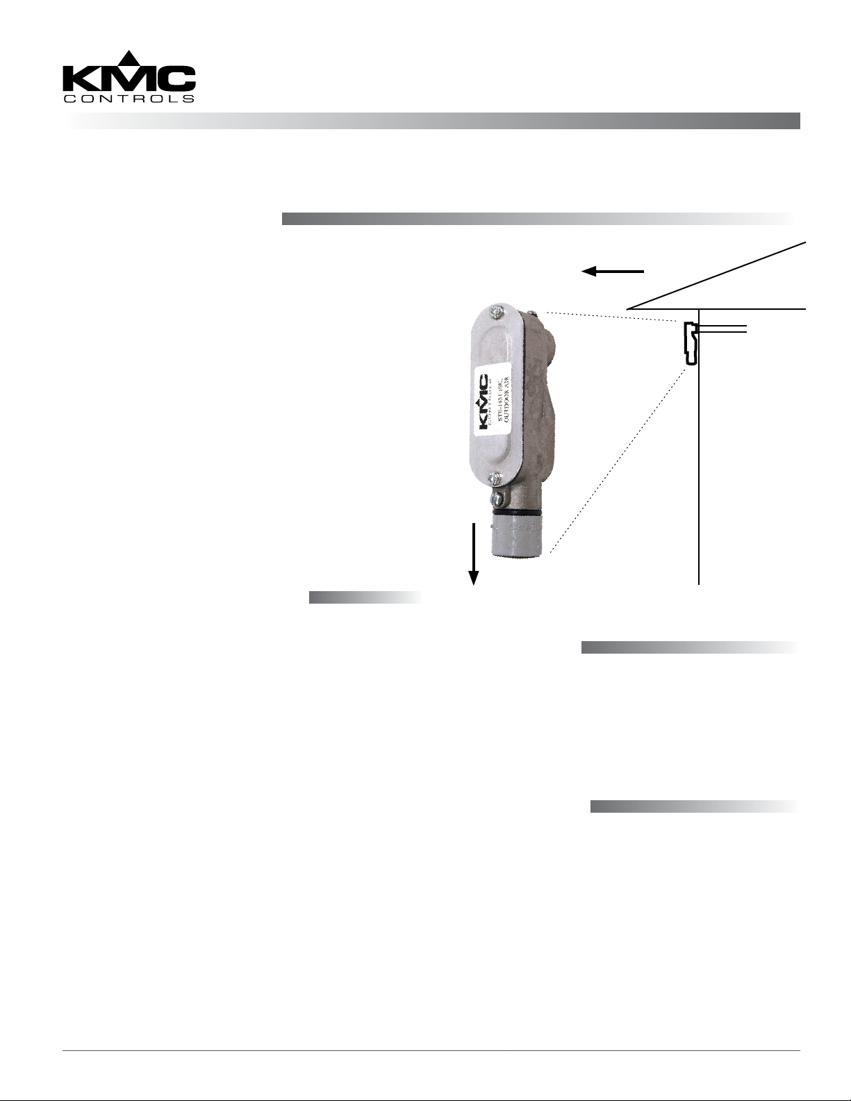
For best results, locate the sensor on the north side
of the structure (when located north of the equator)
high under the eaves or another protected area to
prevent incorrect readings from direct sunlight and
damage due to the elements. Also avoid proximity to
other heat sources, power wires, or a large thermal
mass.
1. Run 1/2" conduit through the wall.
2. Aach the conduit to the sensor enclosure’s CW
1/2" NPT ing with a suitable coupler (such as a
Chase closed nipple).
Note: The sensor air holes must face down to
prevent the accumulation of dirt or water.
Connections and Wiring
1. Remove the two cover screws and cover.
NOTE: Removal of only one screw is absolutely
required. The other screw can be loosened,
and the cover can be swung out of the way.
2. Feed wires through the conduit opening.
3. Make connections to the two wire leads with
either bu-splices or solder. (Using wire nuts is
not recommended.) The two-wire sensor is not
polarity sensitive.
4. Plug the conduit with plumber’s puy, painter’s
puy, caulk, or other sealant to prevent air
inltration.
5. Check that the rubber weather gasket is placed
correctly between the enclosure and cover.
6. Reinstall the cover and tighten the screws to
create a weather-resistant seal.
North
1/2"
OAT Sensor
Down
Conduit
Maintenance
No routine maintenance is required. Each component is designed for dependable, long-term reliability
and performance. Careful installation will also
ensure long term reliability and performance. If dirt
clogs the air holes at the boom, remove it.
Specifications
Sensor Type III thermistor, 10K ohm
@ 77° F (25° C)
Temperature Limits –4 to 221° F (–20 to 105° C)
Wiring 22 AWG wire leads
Case Aluminum LB
STE-1451 1 Installation Guide
Page 2

Configuration
More Information
For controller conguration, see the Type III Sensors
Applications Guide on the KMC web site.
Important Notices
The KMC logo and KMC Controls are registered
trademarks of KMC Controls, Inc.
All rights reserved. No part of this publication may
be reproduced, transmied, transcribed, stored in a
retrieval system, or translated into any language in
any form by any means without the wrien permis-
sion of KMC Controls, Inc.
The material in this document is for information
purposes only. The contents and the product it
describes are subject to change without notice.
KMC Controls, Inc. makes no representations or
warranties with respect to this document. In no event
shall KMC Controls, Inc. be liable for any damages,
direct or incidental, arising out of or related to the
use of this document.
For additional information,
see the STE-1400 Series
Data Sheet on the KMC
web site.
For troubleshooting, con-
troller conguration, and
other information, see the
Type III Sensors Applications Guide on the KMC
web site.
KMC Controls, Inc.
19476 Industrial Drive
New Paris, IN 46553
574.831.5250
www.kmccontrols.com
info@kmccontrols.com
STE-1451 2 Installation Guide© 2014 KMC Controls, Inc. 717-019-18C
 Loading...