

Page 1
Mounting
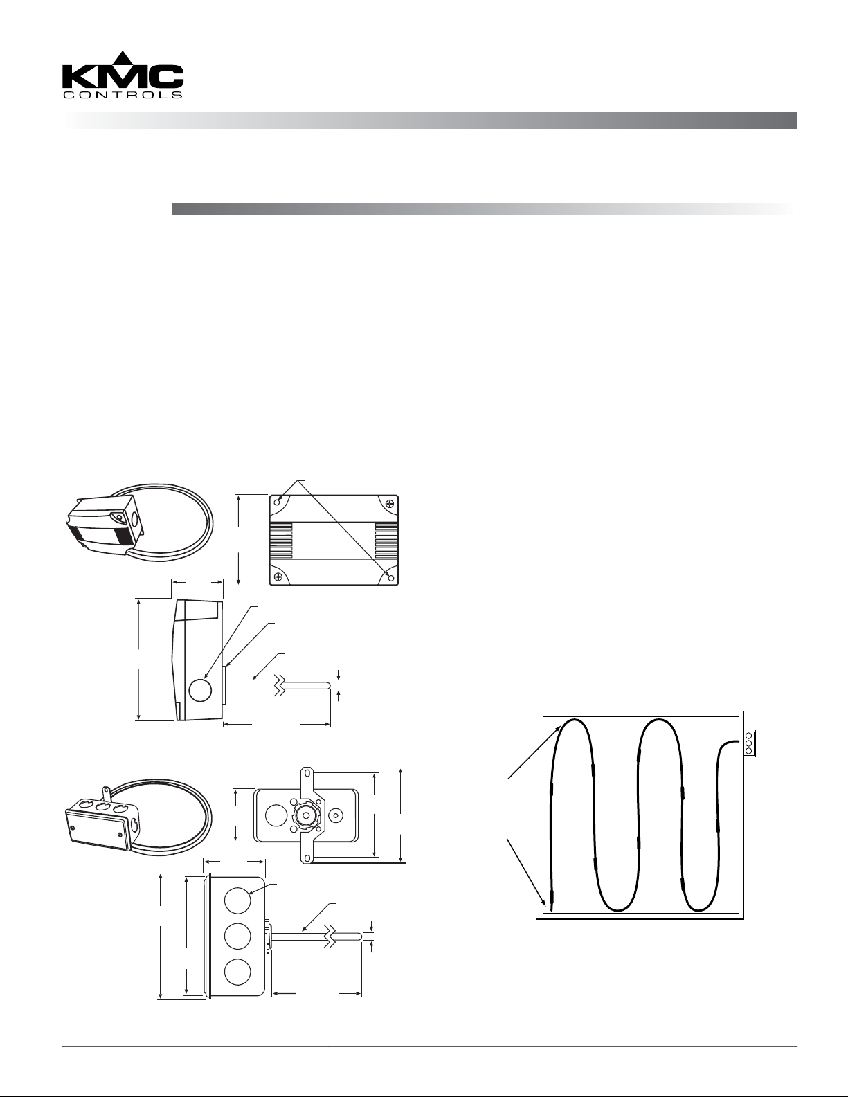
Duct Temperature Sensor, Averaging (Copper Tubing)
STE-1411/1412/1413/1414
Installation Guide
The averaging temperature sensor incorporates several discrete sensors encapsulated at equal distances
across the length of the copper tubing probe. The
complete assembly acts as a single sensor to monitor the average temperature in a duct. Averaging
elements are not recommended for high humidity
applications.
The copper tubing can be installed onto hangers in
the duct using tube clamps or wire ties. It should
be located in a straight section of duct away from
heating, cooling, or humidier elements.
Mounting Holes (X2) Ø 0.200"
84.3 mm
3.320"
(Standard)
Plastic Enclosure
115.8 mm
4.56"
53.6 mm
2.110"
2X Ø 0.850"
Foam Gasket
Soft Copper Probe
Various
Probe
Lengths
7.94 mm
0.3125"
Temperature sensors can be aected by air stratication in the duct, air leakage through the conduit
or other duct holes, and nearness to exterior walls,
a large thermal mass (e.g., concrete blocks), heat
sources, or wires with power.
Because of air stratication, the coldest air tends to
be toward the boom of the duct. Hence, one of the
sensors inside the tubing should be near the boom
of the duct.
1. Cut a hole in the duct large enough to feed the
copper probe through the back of the sensor
enclosure.
2. Fasten the enclosure to the duct by drilling holes
in the duct and threading screws through the
mounting holes in the case.
3. Insert the sensor probe into the duct, bend the
probe tubing to cover the air path, and secure
as needed. Maintain a minimum bend radius
of six inches to prevent damage to the wires or
sensors.
4. For the cable leading to the building automation
system controller, aach conduit to a hole in one
of the sides.
84.3 mm
53.3 mm
2.10"
51.8 mm
Metal Enclosure (M)
107.7 mm
4.24"
101.6 mm
4.0"
STE-1411/1412/1413/1414 1 Installation Guide
2.04"
8X Ø 0.875"
Various
Probe
Lengths
3.452"
98.4 mm
3.875"
Soft Copper Probe
7.94 mm
0.3125"
Use
Tie Wraps
to Secure
Tubing
6"
Min.
Bend
Radius
Page 2

Connections and Wiring
More Information
1. Feed wires from the controller through the
conduit opening.
2. Make connections to the two sensor wire leads
with either bu-splices or solder. (Using wire
nuts is not recommended.) The two-wire sensor is
not polarity sensitive.
3. Plug the conduit with plumber’s puy, painter’s
puy, caulk, or other sealant to prevent air
inltration.
Configuration
For controller conguration, see the Type III Sensors
Applications Guide on the KMC web site.
Maintenance
No routine maintenance is required. Each component is designed for dependable, long-term reliability and performance. Careful installation will also
ensure long term reliability and performance.
Specifications
Sensor Type III thermistor, 10K ohm @
77° F (25° C)
Temperature Limits –4 to 221° F (–20 to 105° C)
Wiring 22 AWG wire leads
Enclosure Materials Flame-retardant ABS plastic or
galvanized steel
Probe Lengths and Number of Discrete Sensors
For additional information,
see the STE-1400 Series
Data Sheet on the KMC
web site.
For troubleshooting, con-
troller conguration, and
other information, see the
Type III Sensors Applications Guide on the KMC
web site.
Important Notices
The KMC logo and KMC Controls are registered
trademarks of KMC Controls, Inc.
All rights reserved. No part of this publication may
be reproduced, transmied, transcribed, stored in a
retrieval system, or translated into any language in
any form by any means without the wrien permission of KMC Controls, Inc.
The material in this document is for information
purposes only. The contents and the product it
describes are subject to change without notice.
KMC Controls, Inc. makes no representations or
warranties with respect to this document. In no event
shall KMC Controls, Inc. be liable for any damages,
direct or incidental, arising out of or related to the
use of this document.
STE-1411 6 feet (1.8 m), 4 sensors
STE-1412 12 feet (3.6 m), 4 sensors
STE-1413 24 feet (7.3 m), 9 sensors
STE-1414 20 feet (6.1 m), 4 sensors
KMC Controls, Inc.
19476 Industrial Drive
New Paris, IN 46553
574.831.5250
www.kmccontrols.com
info@kmccontrols.com
STE-1411/1412/1413/1414 2 Installation Guide
© 2014 KMC Controls, Inc. 717-019-15D
 Loading...