

Page 1

Applications Guide
Type III Temperature Sensors
STE-1400 and Other Series
Contents
Introduction ...................................................................1
Mounting Considerations ...............................................1
Troubleshooting .............................................................1
Controller Configuration ................................................2
Overview ....................................................................2
BAC-A1616BC BACnet Building Controller ................2
BACstage Software .....................................................2
TotalControl Software ................................................3
WinControl Software..................................................3
Important Notices ..........................................................3
Maintenance ..................................................................3
Introduction
This document gives conguration, troubleshooting, and other related information for temperature
sensors using Type III thermistors. For mounting,
wiring, and specications, see the respective product
installation guide and data sheet (STE-1400 Series
Data Sheet for STE-14xx sensors).
For information about Type II thermistor sensors,
see:
• STE-6010/6011/6013/6015 Application Guide for
room temperature sensors with optional override
buon and LED indicator.
• STE-6014/6017/6018/6019/6020 Application
Guide for room temperature sensors with rotary
setpoint dials and optional override buon and
LED indicator.
• STE-6012/6016 Application Guide for room
temperature transmiers with LCD displays.
The latest support les are always available on the
KMC Controls web site (www.kmccontrols.com).
Mounting Considerations
Depending on the application, space temperature
sensors generally should NOT be:
• Mounted on an exterior wall.
• Mounted on or near a large thermal mass (e.g.,
concrete block wall).
• Blocked from normal air circulation by obstructions.
• Exposed to heat sources (e.g., lights, computers,
copiers, or coee makers) or to sunlight (at any
time of the day).
• Exposed to drafts from windows, diusers, or
returns.
• Exposed to air ow through the conduit (from
leaks in plenum ducts)—put plumber’s puy,
painter’s puy, caulk, or other sealant inside the
conduit to block air ow.
Apply what is relevant to other applications (e.g.,
duct sensor).
Troubleshooting
• Be sure the 10,000 ohm pull-up resistors on the
controller board are selected/turned ON.
• Check wiring. To prevent excessive voltage drop,
use a conductor size that is adequate for the
wiring length!
• Check sensor conguration and tables in the
controller.
• Check voltage from the controller.
• Check that the sensor is mounted correctly. (See
the Mounting Considerations section above.)
Type III Temperature Sensors 1 Applications Guide, AN1013A Rev. B
Page 2
Controller Configuration
Overview
Ensure that the corresponding 10,000 ohm pull-up
resistors on the controller are selected (switched
On). Consult the controller’s setup instructions for
information on switching on the pull-up resistors.
See the relevant software section for controller
conguration instructions.
BAC-A1616BC BACnet Building Controller
Select the 10K ohm pull-up resistor jumper position for the corresponding input. (See the Installa-
tion section of the BAC-A1616ABC Building Controller Installation and Operation Guide for the correct
jumper position.)
Because the Building Controller has a 0–12 VDC
total input range, dierent tables are required than
in other (0–5 VDC) KMC controllers. If needed,
download the sensor tables (CSV) le from the
KMC Controls Partners web site and import the
needed tables as described in the Tables section of
the BAC-A1616ABC Building Controller Installation and Operation Guide. (You must log into the
Partners site to see the zipped tables le on the
Building Controller product page downloads.)
1. In the desired Analog Input setup screen of the
web page interface, select KMC Type III Degree
Fahrenheit or KMC Type III Degree Celsius.
2. Select the Lookup Table for the Type III
Thermistor. (Having it in Table 3 is good
practice.)
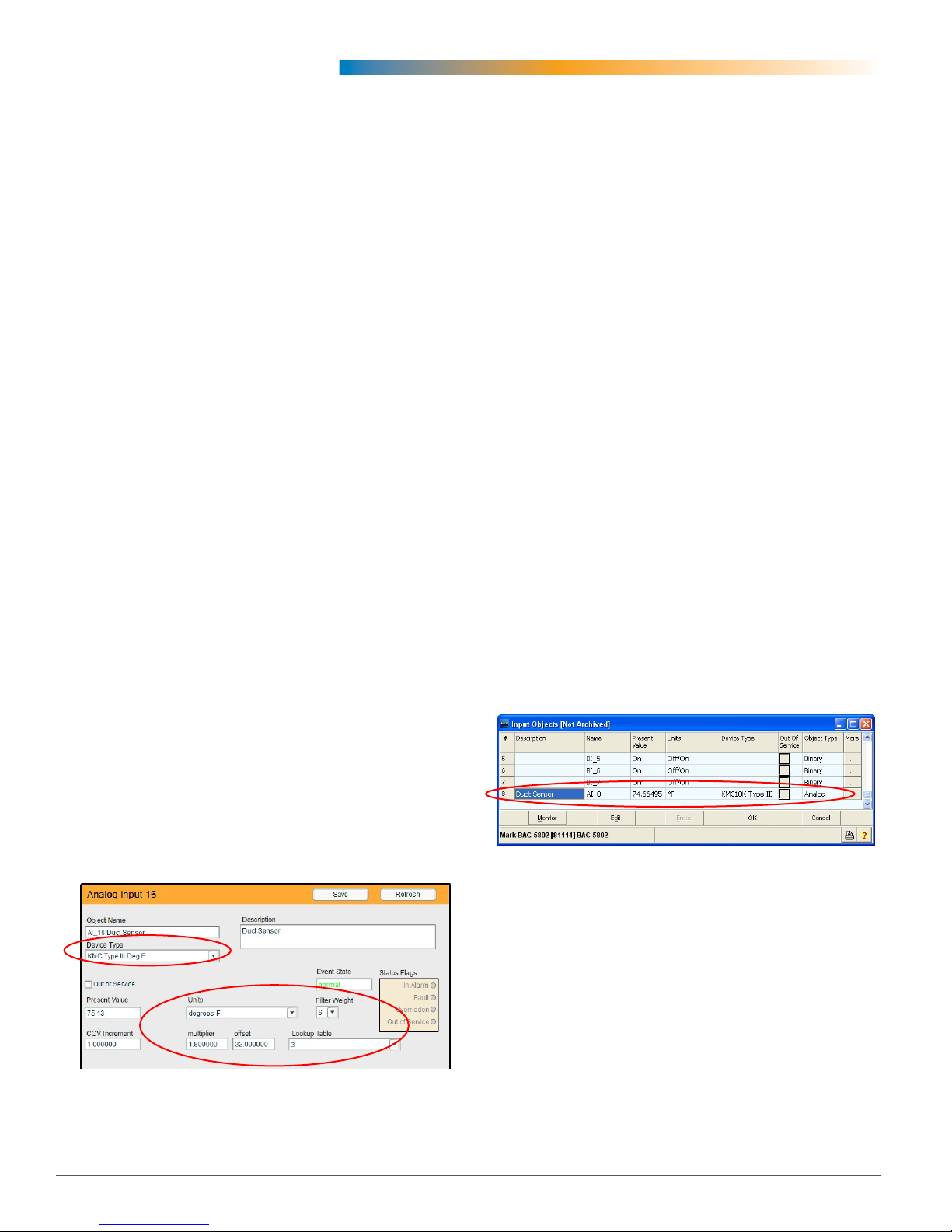
BACstage Software
1. In the BACstage software main menu, select
Objects > Inputs.
2. Click Edit.
3. Type in a name in the appropriate Description
eld (up to 32 characters) and/or Name eld (up
to 16 characters).
NOTE: No two labels or descriptions in a controller
can be identical.
4. Select Object Type: Analog if it is not the default.
5. Select Device Type: KMC10K Type III.
6. Select Units: °F or °C.
7. Optionally, change the Filter Weight (under More)
to the desired number of thermistor readings
averaged before displaying the result.
8. Click End Edit.
9. Click Yes for “Send Update Notication Now?”
10. In the BACstage software main menu, select
Device > Device Tables > KMC10K Type III Table.
11. Click Edit.
12. Click Defaults (values will ll in).
13. Click End Edit.
14. Click Yes for “Send Update Notication Now?”
15. Click OK.
3. For the Fahrenheit scale, the multiplier is 1.8 and
the oset is 32. For Celsius, the multiplier is 1 and
the oset is 0.
4. Click Save.
NOTE: See also TotalControl Software on page
3.
Type III Temperature Sensors 2 Applications Guide, AN1013A Rev. B
Page 3

TotalControl Software
WinControl Software
NOTE: Follow the relevant hardware instructions
in the BACstage Software section or
WinControl Software section. Then see
the TotalControl Help information for
the equivalent software conguration in
TotalControl.
NOTE: TotalControl assumes the Type III
thermistor table is in Table 3 of the Building
Controller.
1. In the WinControl software main menu, select
Control > Inputs.
2. Click Edit.
3. Type in a name in the appropriate Description
eld (up to 20 characters) and/or Label eld (up to
8 characters).
NOTE: No two labels or descriptions in a controller
can be identical.
4. Click Units (which opens the Congure Inputs
screen).
5. Select Type: Analog if it is not the default.
6. Select Deg F (or C) KMC10K Type III.
7. Optionally, change Format from 0 to the desired
number of temperature decimal places.
8. Optionally, change the Average to the desired
number of thermistor readings averaged before
displaying the result.
9. Click OK.
10. Click End Edit.
Important Notices
The KMC logo and KMC Controls are registered
trademarks of KMC Controls, Inc.
All rights reserved. No part of this publication may
be reproduced, transmied, transcribed, stored in a
retrieval system, or translated into any language in
any form by any means without the wrien permission of KMC Controls, Inc.
The material in this document is for information
purposes only. The contents and the product it
describes are subject to change without notice.
KMC Controls, Inc. makes no representations or
warranties with respect to this document. In no event
shall KMC Controls, Inc. be liable for any damages,
direct or incidental, arising out of or related to the
use of this document.
11. Click OK.
Maintenance
No routine maintenance is required. Each component is designed for dependable, long-term reliability and performance. Careful installation will also
ensure long-term reliability and performance.
KMC Controls, Inc.
19476 Industrial Drive
New Paris, IN 46553
574.831.5250
www.kmccontrols.com
info@kmccontrols.com
© 2014 KMC Controls, Inc. AN1013A Rev. B
Type III Temperature Sensors 3 Applications Guide, AN1013A Rev. B
 Loading...