

Page 1
Proportional to Tri-State Control, Relay Module
Installation Guide
REE-5525
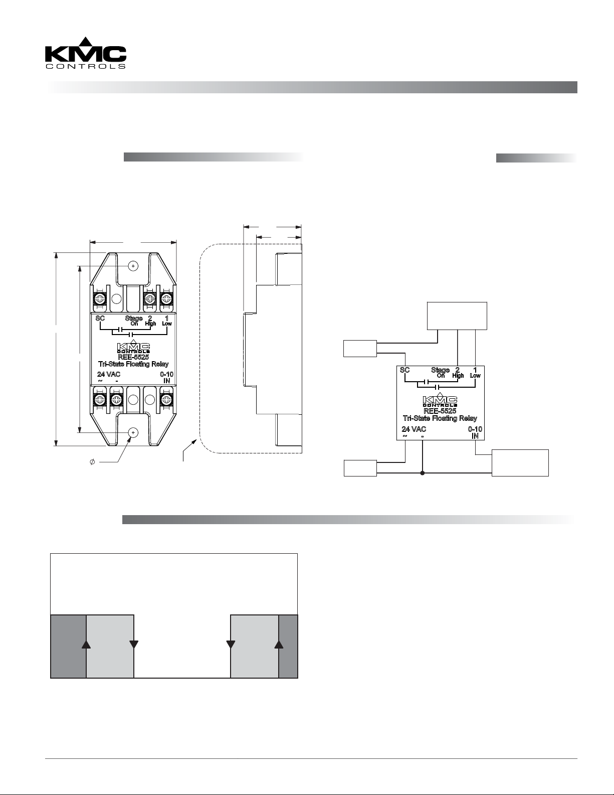
Mounting
The module may be mounted directly to a control
box surface or in a 2 x 4" electrical handy box. Add a
blank cover to conceal the module if desired.
All dimensions are in inches
1.69
3.77
3.25
1.13
0.88
Connections and Wiring
Connect as shown. Supply the relay with 24 VAC
(+20%/–15%, Class 2 only). (Use wire size of 14 to 22
AWG, stranded.)
NOTE: The 24 VAC sources can be the same or
separate, with no regard to phasing.
NOTE: Triac outputs are for 24 VAC loads only.
Outputs are optically isolated from the
control 24 VAC power.
ACTUATOR
COM CW CCW
24 VAC
TYPICAL
APPLICATION
0.19
MOUNTING HOLES
FITS STANDARD 2" DEEP x 2-1/8"
UTILITY BOX & BLANK COVER PLATE
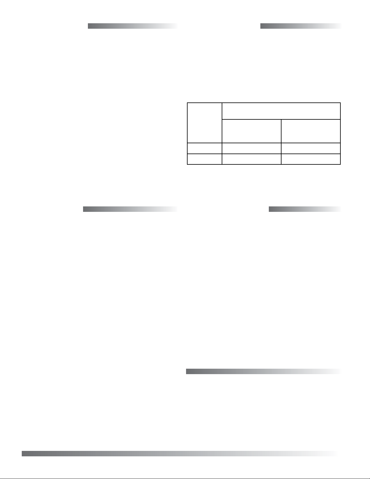
Sequence
SEQUENCE
STAGE 2 ONSTAGE 1 ON
BOTH
STAGES
OFF
0 1.5 3.5 5 7.5 9.5 10
INPUT SIGNAL VDC
+
0–10 VDC
24 VAC
–
SIGNAL
The stage sequence operates in this manner:
• Stage 1 turns on at or below 1.5 VDC* and o at
or above 3.5 VDC. (It is on at 0 VDC.)
• Stage 2 turns on at or above 9.5 VDC* and turns
o at or below 7.5 VDC. (It is on at 10 VDC.)
• Both outputs are o between 3.5 and 7.5 VDC.
*NOTE: In the dark grey regions of the chart, the
stage is denitely on for the given voltage.
In the light grey regions, however, on or
o depends on the previous state. For
example, at 2 VDC, Stage 1 will be on if the
previous voltage was 0 VDC (Stage 1 on)
but o if the previous voltage was 5 VDC
(Stage 1 o).
REE-5525 Relay Module 1 Installation Guide
Page 2
Specifications
Supply Voltage 24 VAC (+20%/–15%) @ 1 VA
plus output loads, Class 2 only
Input Signal 0 to 10 VDC
Switching Dierential 2 VDC (see Sequence chart)
Output Types Optically isolated triacs, zero
crossing
Output Capacity 30 VAC max., 12 VA
Connections Plated screw terminals
Wire Size 14–22 AWG, stranded
Material Beige ame-retardant plastic
Weight 2 oz. (57 grams)
Approvals SASO PCP Registration KSA
R-103263
Temperature Limits
Operating 32 to 120° F (0 to 49° C)
Shipping –40 to 160° F (–40 to 71° C)
Troubleshooting
• Check the wiring.
• Check the voltage from the controller, measured
from Terminal – (under 24 VAC) to Terminal
0–10 IN. (See the Sequence chart on the previous
page.)
• Check the voltage across the triac and load. (See
the chart below.)
Normal Triac Voltage (Approximate and With Load)
Stage Status
On 24 VAC 1 VAC
BOTH Off 0 VAC 24 VAC
NOTE: Triac outputs are for 24 VAC loads only.
Across Load
(Actuator Common to
Terminal 1 or 2)
Across Triac
(Terminal SC to
Terminal 1 or 2)
Maintenance
No routine maintenance is required, however protection from extremes of humidity and dirt is recommended. Careful installation will also ensure long
term reliability and performance.
Important Notices
The material in this document is for information purposes only. The contents and the product it describes
are subject to change without notice. KMC Controls,
Inc. makes no representations or warranties with
respect to this document. In no event shall KMC Controls, Inc. be liable for any damages, direct or incidental,
arising out of or related to the use of this document.
KMC Controls, Inc.
19476 Industrial Drive
New Paris, IN 46553
574.831.5250
www.kmccontrols.com
info@kmccontrols.com
REE-5525 Relay Module 2 Installation Guide
© 2014 KMC Controls, Inc. 809-019-05A
 Loading...