

Page 1
Installation Guide
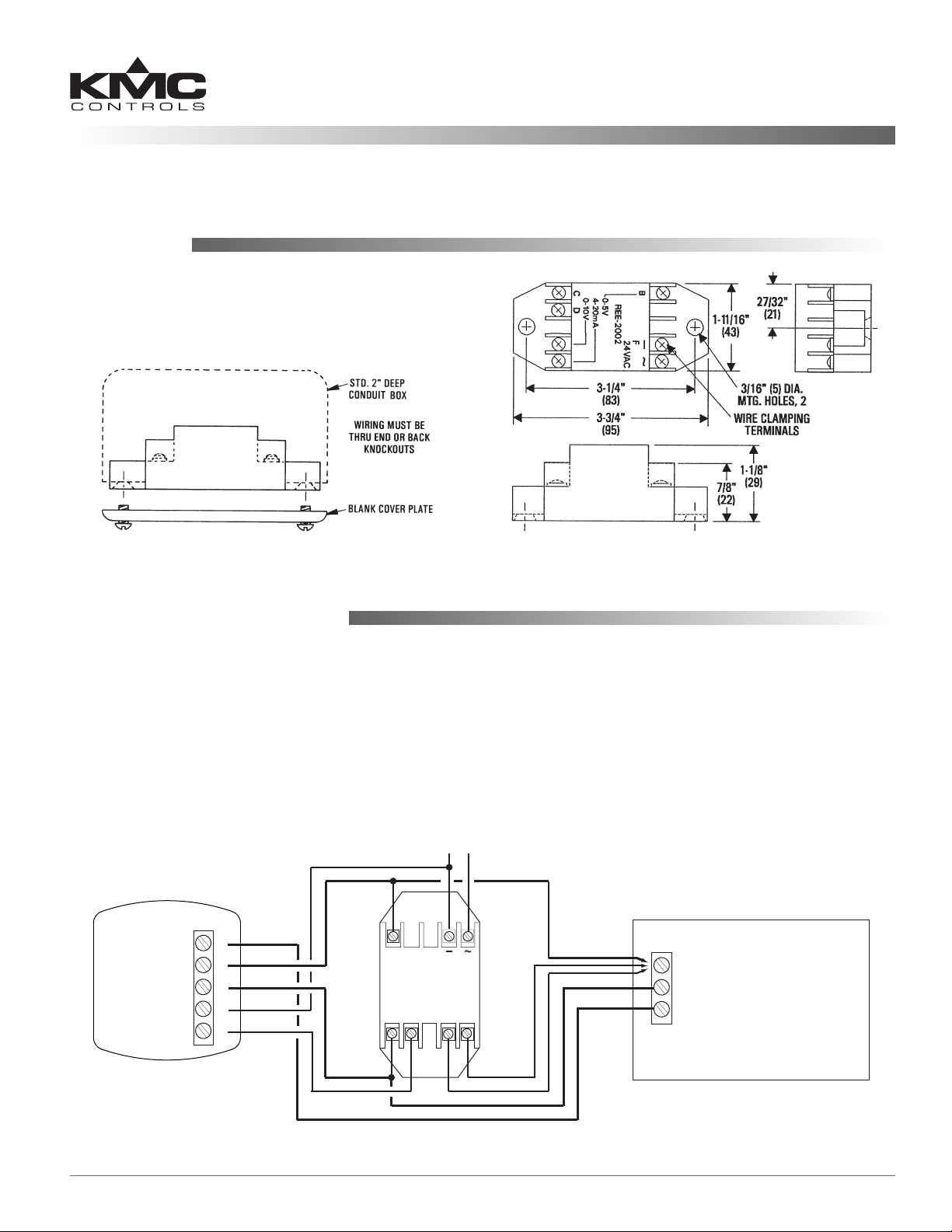
Mounting
The module may be mounted directly to a control
box surface or in a 2 x 4" electrical handy box. Add a
blank cover to conceal the module if desired.
Power Supply and E-E/I Converter Module
REE-2002
Connections and Wiring
1. Connect a controller input to one of the three
THE-1102/REE-2002 (0–5 VDC, 0–10 VDC, 4–20
mA) outputs as shown in the sample illustration
below.
2. Connect the B, F, C, and D terminals to the
corresponding terminals on the THE-1102.
3. Supply the REE-2002 with 24 VAC (+20%/–15%)
from a Class 2 transformer (only).
24 VAC
THE-1102
Temp. Output
(10K Thermistor)
Humidity Output
(0-5 VDC)
Signal Ground
– Power Ground
+ 10-15 VDC Power
A
B
C
F
D
B
0-5 VDC
GND
C D
24 VAC
REE-2002
+
0-10
VDC
F
NOTE: Use wire size 14 to 22 AWG, stranded.
NOTE: See also the THE-1102 Installation Guide
for additional information about this
application. (The THE-1101 has been
discontinued.)
Phase Neutral
(Without the REE-2002, only the THE-1102’s 0-5 VDC humidity
output and thermistor signal are available to a controller)
Controller
Humidity Input*
Signal Ground
4-20
mA
Temp. Input
*Load between Humidity Input and Signal Ground
is 250 ohms min. to 650 ohms max. for 4-20 mA
or 1000 ohms min. for VDC
REE-2002 1 Installation Guide
Page 2
Specifications
Maintenance
Supply Voltage 24 VAC (+20%/–15%), Class 2
only
Input Power
Output Capacity
0–10 VDC output into 1000
4–20 mA output into 250 ohms
Connections Plated screw terminals
Wire Size 14–22 AWG, stranded
Material Flame-retardant plastic
Weight
Temperature Limits
Operating 40 to 120° F (4 to 49° C)
Shipping –40 to 140° F (–40 to 60° C)
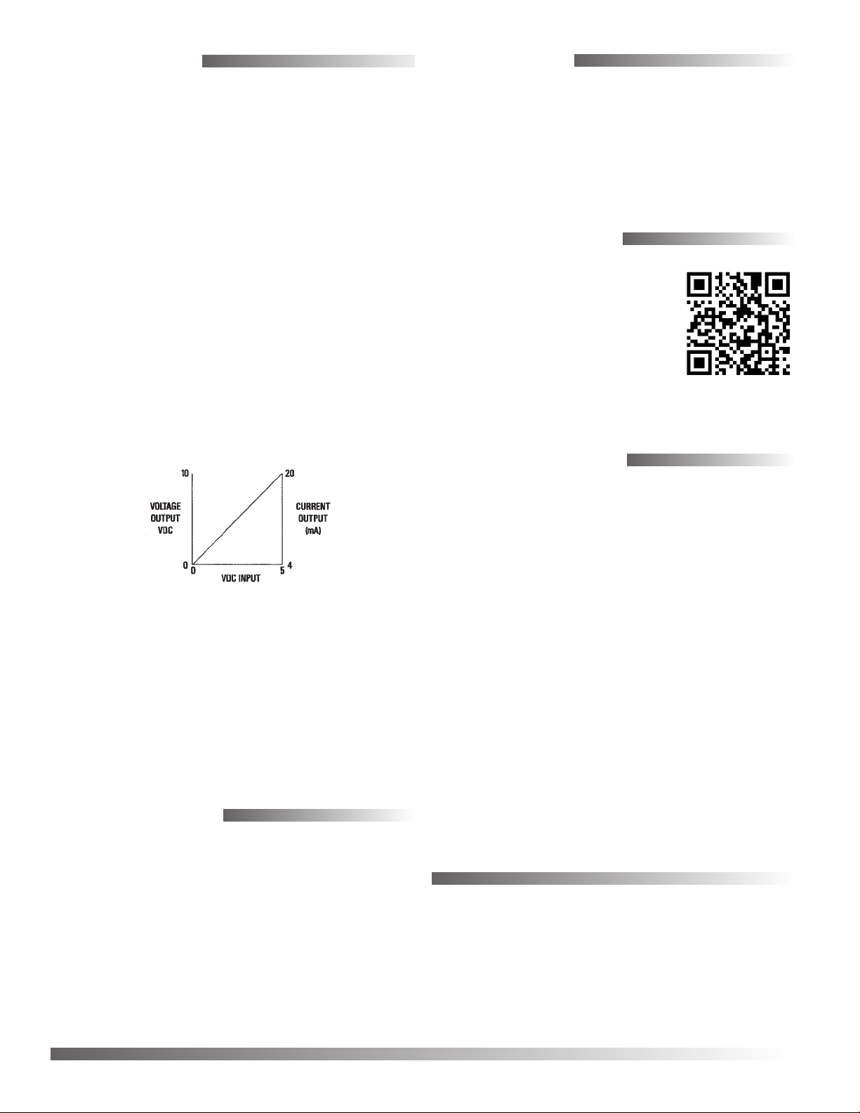
NOTE: The REE-2002 may also be used to convert
0.75 VA at 24 VAC
ohms or greater
min. and 650 ohms
2 oz. (57 grams)
0–5 VDC signals from building automation
systems to 0–10 VDC or 4–20 mA signals.
See the graph for output options over a 0–5
VDC input range.
max.
No routine maintenance is required, however protection from extremes of humidity and dirt is recommended. Careful installation will also ensure long
term reliability and performance.
More Information
For more information about
using the THE-1102 with the
REE-2002, see the THE-1102
Installation Guide.
Important Notices
The material in this document is for information
purposes only. The contents and the product it
describes are subject to change without notice.
KMC Controls, Inc. makes no representations or
warranties with respect to this document. In no event
shall KMC Controls, Inc. be liable for any damages,
direct or incidental, arising out of or related to the
use of this document.
Troubleshooting
• Check the wiring.
• Check the voltages.
KMC Controls, Inc.
19476 Industrial Drive
New Paris, IN 46553
574.831.5250
www.kmccontrols.com
info@kmccontrols.com
REE-2002 2 Installation Guide
© 2013 KMC Controls, Inc. 884-019-02F
 Loading...