

Page 1

Installation and
Operation Guide
NetSensor
KMD-1261 and KMD-1281
Motion, temperature and humidity
sensors
®
Contents
Specifications ............................................................... 2
Network cable preparation ........................................... 6
Rough-in preparation ................................................... 6
Installing the NetSensor ................................................ 7
PC data port ................................................................. 8
Operation .................................................................... 9
Maintenance .............................................................. 10
Programming ............................................................. 11
903-019-10
Page 2

KMC Controls
Specifications
Display LCD, 4-character, 7-segment,
in. high. (temperature)
0.375
Compatibility KMD-5800 series controllers
KMD-7000 series controllers
BAC-5800 series BACnet controllers
BAC-7000 series BACnet controllers
Controller Connection
Connector type Six-wire RJ-12 modular jack
Cable type and length Up to 75 feet (22.9 meters) maximum;
conductors no smaller than 24 AWG
Power 5 volts DC supplied from the connected
controller
Mounting Surface mount directly to any flat
surface or to a 2 x 4 inch or 4 x 4 inch
handy-box. Mounting on a 4 x 4 inch
box requires a mounting backplate.
Weight 2.8 ounces (80 grams)
Material Light almond or white plastic
Accessories
Mounting backplate
Almond 4 x 4 inch HMO-1161
White 4 x 4 inch HMO-1161W
Gasket HPO-1161
Replacement Allen screws HPO-0044 (package of 10)
Network plenum cables with connectors
25 feet (7.6 meters) KMD-5690
50 feet (15.2 meters) KMD-5691
75 feet (22.9 meters) KMD-5692
2
Page 3

NetSensor Installation and Operation
PC data port interfaces See “PC data port” on page 8.
Sensor Accuracy, KMD-1261
Typ e Thermistor
Accuracy ±0.36° F (±0.2° C)
Resistance 10,000 at 77° F (25° C)
Operating range 48° to 96° F (8.8° to 35.5° C)
Sensor Accuracy, KMD-1281
Typ e CMOS
Humidity
Range 0 to 100% Relative humidity
Accuracy at 25°C ±2% from 10–90% Relative humidity
Response time Less than or equal to 4 seconds
Tem pe ra tur e
Accuracy ±0.9° F (±0.5° C) Offset from
40 to 104° F
(4.4 to 40.0° C) Offset is adjusted
through configuration software
Resolution ±0.1°F (±0.1° C)
Operating range 36 to 120° F (2.2 to 48.8° C)
Response time 5 to 30 seconds
Environmental Limits
Operating Temperature 34° to 125° F (1.1 to 51.6° C)
Shipping –40° to 140° F (–40°C to 60° C)
Humidity 0 to 95% Relative humidity
3
non-condensing
Page 4
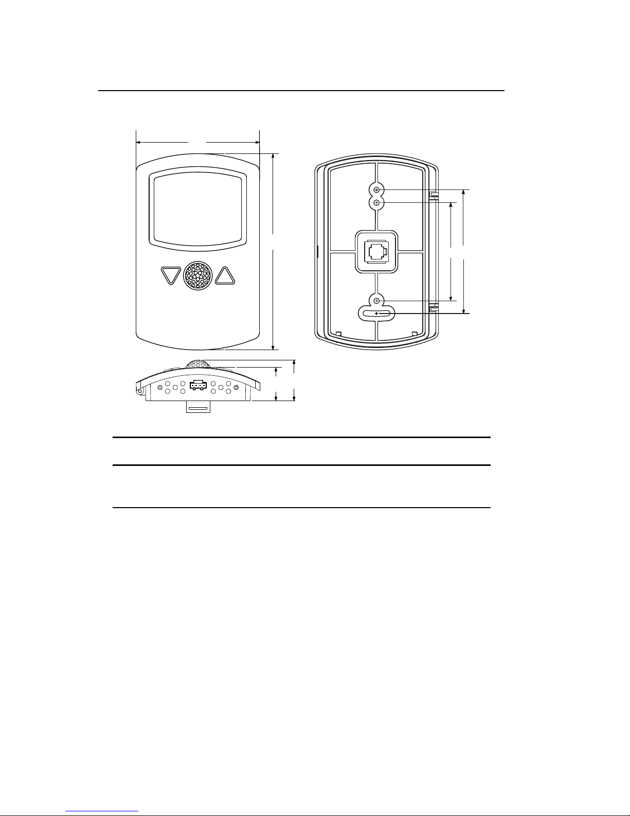
Dimensions
A
C
D
E
B
F
KMC Controls
AB CDE F
3.25 in. 5.16 in. 2.58 in. 3.25 in. 0.87 in. 1.07 in.
83 mm 131 mm 66 mm 83 mm 22 mm 27 mm
4
Page 5

NetSensor Installation and Operation
55
°
10 m
32.8 ft
10 m
32.8 ft
X
0°
10 m
32.8 ft
10 m
32.8 ft
0°
46.5
°
Y
Top view
Side view
Motion sensor range 33 feet (10 meters)
Models KMD-1261 and KMD-1281 detect motion and change the
value of the auxiliary function.
• A value of -1 indicates motion
• A value of -2 indicates no motion
• A value of 0 or 1 indicates the auxiliary function is active.
The value of the auxiliary function will remain at 0 for approximately
30 seconds after power is applied to the NetSensor.
Models
Temperature only
Almond KMD-1261
White KMD-1261W
Temperature and humidity
Almond KMD-1281
White KMD-1281W
5
Page 6

KMC Controls
Caution
RJ-12
Network cable preparation
Connecting a NetSensor to a controller requires a six-wire cable with
RJ-12 connectors on each end. KMC plenum-rated preassembled
cables are recommended. Cables made to length must meet the
following requirements:
◆ Cable length must be no longer than 75 feet (22.9 meters).
◆ Cable conductors must be no smaller than #24 AWG.
◆ Cable insulation must meet local building codes.
◆ Connectors must be appropriate for the cable in use and are
installed following the connector manufacturers instructions.
Rough-in preparation
To prevent mounting screw heads from touching the circuit
board in the NetSensor, use only the mounting screws
supplied by KMC Controls. Using screws other than the
type supplied will damage the NetSensor.
Cable details
6
Page 7

NetSensor Installation and Operation
Network
cable
Allen
screws
Mounting
base
Turn clockwise to
remove from base.
Complete rough-in wiring at each sensor location prior to sensor
installation. This includes the following.
◆ Routing the network cable from the NetSensor to a controller.
◆ If required, installing the appropriate backplate. See Accessories
on page 2 for model numbers.
NetSensor mounting details
Installing the NetSensor
1. Turn the Allen screws in the base of the NetSensor clockwise
until they clear the cover. Swing the sensor away from the
mounting base to remove it.
Mounting screws
2. Route the RJ-12 cable through the mounting base.
3. Fasten the mounting base directly to a 2 x 4 inch outlet box or a
backplate with the Allen screws toward the floor.
4. Insert the RJ-12 cable coming from the base into the NetSensor.
5. Place the top of the NetSensor over the top of the mounting base
and swing it down over the Allen screw brackets. Be careful not
to pinch any wiring.
6. Back the Allen screws out of the brackets until they engage the
NetSensor cover and hold it in place.
7
Page 8

KMC Controls
PC data port
The NetSensor is equipped with a PC data port located at the bottom
of the NetSensor housing. This port provides a temporary connection
for setup or troubleshooting to either KMD Tier 2 or BACnet MS/TP
networks.
NetSensor PC port location and USB connection
To use the port to connect to a computer, use one of the following
connection methods. The exact connection depends on the computer
and the operator workstation software (see also the instructions
included with those devices and software):
◆ For a USB connection with either WinControl or BACstage, use a
KMD-5576 USB Communicator (see the illustration above).
◆ For a serial port connection to BACstage, use a third-party
interface.
◆ For serial port connection to WinControl, use a KMD-5559
CommTalk and KMD-5624 cable.
To use the PC data port:
1. Connect the keyed, flat end of the KMD-5624 NetSensor
interface cable to the port on the NetSensor. The KMD-5624
cable is included with the KMD-5576 but not the KMD-5559.
2. Connect the RJ-12 end of the cable to the interface device that
converts the EIA-485 signal from the NetSensor into a USB or
EIA-232 signal.
3. Connect the suitable cable from the interface device to the
computer ’s serial or USB port. Install any required software and
configure the port as necessary.
8
Page 9

NetSensor Installation and Operation
Setpoint
Operation
The following sections describe the controls and indicators found on
the NetSensor.
Display The temperature display contains four 0.375-inch, 7-segment
LCD digits that are visible across a normal size office. The display
provides time, temperature and on the KMD-1281 humidity
readouts. Room temperature is displayed until either setpoint button
is pressed and then the display changes to setpoint mode.
Controls Models KMD-1261 and KMD-1281 include eight push
buttons; six of which (button 1 and buttons 3-7) are user
programmable. The actual operation of the programmable buttons
depend upon the program in the controller to which the NetSensor is
connected. See Programming
on page 11.
The arrow buttons adjust the programmed values up or down. Values
can be changed for all programmed buttons except the setpoint as
follows:
1. Press the button for the desired function.
2. Adjust the value up or down.
Setpoint Pressing either the up or down arrow buttons changes
the display from room temperature mode to setpoint mode. Each
additional time a setpoint button is pressed and released changes the
setpoint up or down.
Auxiliary function These NetSensors do not have auxiliary wires
found on earlier models. Press buttons 5 and 7 together and then
press an up arrow or down arrow button to change the auxiliary
function.
9
NetSensor buttons
Page 10

KMC Controls
Maintenance
Remove dust as necessary from holes in top and bottom. Clean the
display and motion sensor cover with a soft, damp cloth and mild
soap.
10
Page 11

NetSensor Installation and Operation
1
5
6
7
2
4
3
8/Aux.
Programming
Program a KMD-1261 or KMD-1281 by associating each button with a
variable or value object in the controller to which the NetSensor is
connected.
◆ See the illustration NetSensor button numbers on page 11 for the
button numbers.
◆ Table 1 lists the settings for programming a NetSensor with
WinControl. Use the NetSensor dialog found under the Control
Menu to configure each button.
◆ Table 2 lists settings for programming a NetSensor with
BACstage. Use the NetSensor dialog in the Device Menu to
configure each button.
Additional instructions on programming a NetSensor are included in
the program help for WinControlXL, BACstage, and TotalControl.
11
NetSensor button numbers
Page 12

Button
Table 1 Settings for KMD controllers
NetSensor configuration Variable
Function
Ty p e
Range
Display
KMC Controls
Units
Ty p e
1 Temperature Analog °F or °C Read
Only
2 Setpoint Analog 0 Decimal Read/
Write
5 Time Analog Time Read/
Write
7 Humidity
(KMD-1281
only)
Aux Auxiliary and
Motion
Analog 0 Decimal Read/
Write
Analog 0 Decimal Read/
Write
Deg.F
Deg.C
Deg.F
Deg.C
Time Analog
% RH Analog
Unused Analog
Analog
Analog
12
Page 13

NetSensor Installation and Operation
Table 2 Settings for BACnet controllers
NetSensor
configuration
Button
1 Temperature AV °F or °C Read
2 Setpoint AV 0 Read/
5 Time AV Time Read
7Humidity
(KMD-1281
only)
Function
Assignment
AV 0 Read/
Display format
Permission
Only
Write
Only
Write
Variable
Object type
AV °F or
AV °F or
AV Hours
AV % RH
Units
°C
°C
Aux Auxiliary
and Motion
Temperature Button 1—the space temperature sensor inside of the
NetSensor—is assigned to an analog variable in KMD controllers or
an analog value object in BACnet controllers.
◆ Operators can view the room temperature by pressing Button 1
but cannot change the value.
◆ The setting in Range (WinControl) or Display Format (BACstage)
sets the NetSensror display to either Fahrenheit or Celsius.
AV 0 Read/
Write AV
(No
Units)
13
Page 14

KMC Controls
Setpoint The button 2 function up and down arrow buttons is
assigned to an analog variable in KMD controllers or an analog value
object in BACnet controllers.
◆ The precision of the display is set by Range in WinControl and
Display Format in BACstage. The typical value is 0.
◆ Operators can view and change the setpoint by pressing the
up or down arrow buttons.
◆ Write a Control Basic to control equipment based on the
conditions of the setpoint.
10 IF VAR2 < VAR1 THEN START OUT6
Displaying time Typically button 5 is configured to display time. It is
assigned to an analog variable in KMD controllers or an analog value
object in BACnet controllers. Add a Control Basic line as follows:
10 VAR5 = TIME
Verifying a functioning NetSensor Use NETSENSOR-STATUS in a
Control Basic program to check if a functioning NetSensor is
connected to the controller.
10 IF NOT NETSENSOR-STATUS THEN STOP OUT1
Verifying firmware version Simultaneously push Button 1 and Button
4 to display the version of the firmware in the NetSensor.
Motion sensing Program the Auxiliary function to detect motion in
the room.
• A value of -1 indicates motion
• A value of -2 indicates no motion
• A value of 0 or 1 indicates the auxiliary function is active.
The following Control Basic program detects motion and changes the
state of variable VAR9.
10 IF+ VAR8 = -1 THEN START VAR9 , STOP A
20 IF VAR8 = -2 THEN START A
30 IF TIME-ON( A ) > 0:02:00 THEN STOP VAR9
14
Page 15

NetSensor Installation and Operation
15
Page 16

KMC Controls
Important notices
The KMC logo, WinControlXL and NetSensor are registered
trademarks of KMC Controls, Inc.
TotalControl and BACstage are trademarks of KMC Controls, Inc.
©2010, KMC Controls, Inc.
All rights reserved. No part of this publication may be reproduced,
transmitted, transcribed, stored in a retrieval system, or translated
into any language in any form by any means without the written
permission of KMC Controls, Inc.
Printed in U.S.A.
Disclaimer
The material in this manual is for information purposes only. The
contents and the product it describes are subject to change without
notice. KMC Controls, Inc. makes no representations or warranties
with respect to this manual. In no event shall KMC Controls, Inc. be
liable for any damages, direct or incidental, arising out of or related to
the use of this manual.
16
KMC Controls. Inc.
19476 Industrial Drive
New Paris, IN 46553
TEL: 1.574.831.5250
FAX: 1.574.831.5252
E-mail: info@kmccontrols.com
 Loading...