

Page 1
Installation & Operation Guide
Introduction
KMD-1101/1121 NetSensor
This section provides a brief overview of the KMD-1101/1121 NetSensor. Review
this material before you attempt to install the controller.
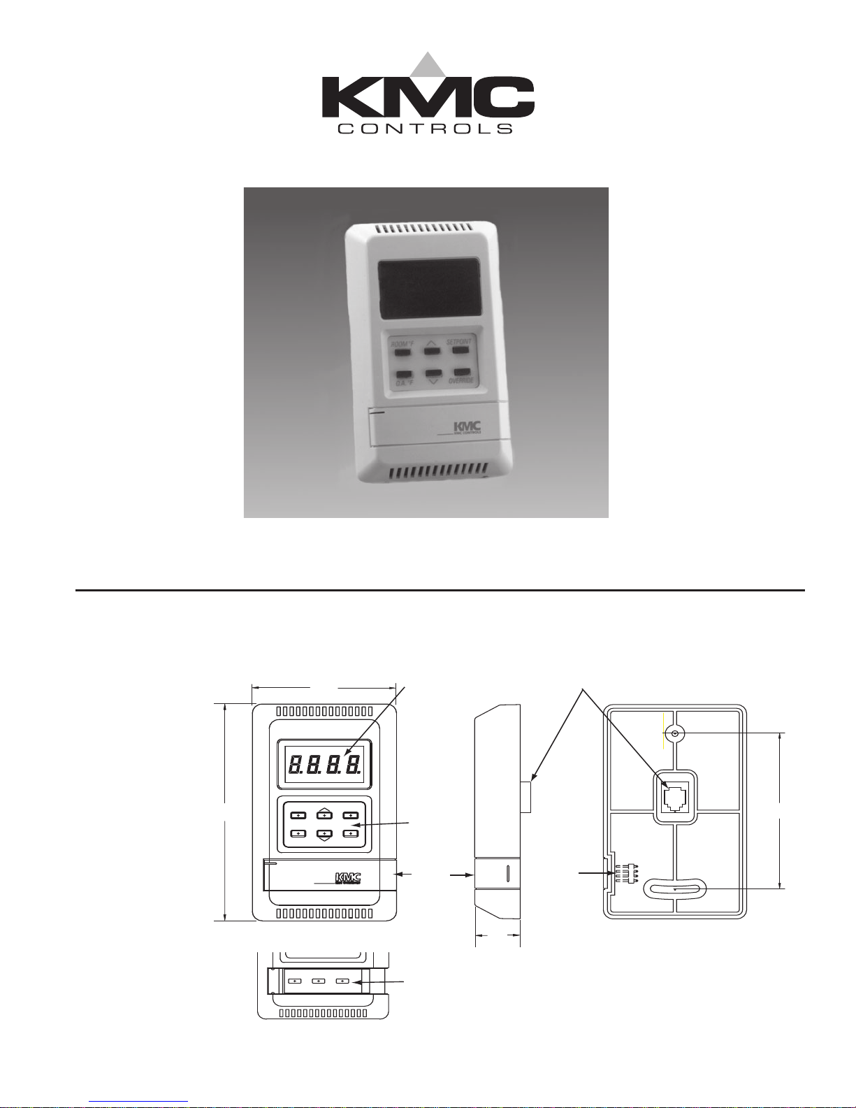
Illustration 1 shows the major components and their locations.
LED Display
Main Control
Buttons
Flip Door
0.875
Secondary Button Group
(Under Flip Door)
RJ–12 Connector
PC Port
NOTE: Actual label text will depend on
application and labels used.
4.500
ROOMROOMûûFF
O.A.O.A.ûûFF
2.750
11TIMETIME
SETPOINTSETPOINT
OVERRIDEOVERRIDE
00
3.280 (83.3)
Illustration 1. NetSensor Component1
893-019-01F
1
Page 2

Installation
Installation
This section provides important instructions and guidelines for installing the
KMD-1101/1121 NetSensors. These boards are designed for use with KMD-5500
and KMD-6000 series controllers.
Carefully review this information prior to attempting installation.
Note:
Preliminary wiring to each sensor location should be completed prior to actual
sensor installation. (This includes the installation of the appropriate mounting
base.) If wiring is not completed, finish that first. Mounting backplates are
available from KMC. (See the appropriate datasheet for accessories.)
To install the NetSensor unit:
1. Turn the Allen screws in the base of the Netsensor clockwise until they clear
the cover then swing the sensor away from the backplate to remove it.
2. Feed the RJ–12 cable through the mounting base.
3. Secure the mounting base to the backplate or the 2” x 4” outlet box with
the Allen screws toward the floor.
4. If the pig-tail leads are being used, connect them to the wires coming from
the wall mount as indicated in the site wiring diagram. Be sure to protect
bare wires with suitable insulating material.
5. Insert the RJ– 12 cable coming from the base into the NetSensor.
6. Place the top of the NetSensor over the top of the mounting base and swing
it down over the Allen screw brackets. Be careful not to pinch any wiring.
7. Back the Allen screws out of the brackets until they engage the NetSensor
cover and hold it in place.
Operation
Controls and Indicators
The following sections describe the controls and indicators found on the
NetSensor.
Display
The display contains four .375-inch, 7-segment LEDs that are visible across a
normal size office. The display can be programmed to remain on constantly, or to
turn off after a set time period. (Refer to the KMD Applications Manual for
programming instructions.)
2
Page 3

Controls
PC Port
The KMD-1101/1121 NetSensors include a total of nine pushbuttons; seven of
which are user programmable. The actual operation of the programmable buttons will depend on the program assigned to the device.
The remaining two buttons will adjust the value (up or down) if this function is
enabled in the programming. Values can be changed for all buttons (if programmed) except the #1 button as follows:
1. Press the button for the desired function.
2. Adjust the value up or down.
The NetSensor is equipped with a PC Port. This port provides a RS–485 connection to the digital network that is accessible by a PC. The port is located beneath
the flip door on the side of the controller.
To use this port:
1. Open the flip door on the front of the controller.
2. Connect the keyed, flat end of the KMD-5624 NetSensor to PC cable to the
port on the NetSensor.
3. Connect the RJ–11 end of the cable to device that converts the RS–485
signal from the NetSensor into an RS–232 signal.
Note:
The KMD-5557 Computer Interface or the KMD-5559 CommTalk are suitable
for this purpose.
4. Connect a suitable cable (such as the KMD-5625) from the interface to the
computer’s serial port.
You should have normal access to the network provided the PC has the proper
software application installed and the serial port is configured properly.
3
Page 4

Disclaimer
The material in this document is provided for information purposes only.
The contents and the product(s) described herein are subject to change
without notice. KMC Controls, Inc. makes no representations or warranties
with respect to this document. In no event shall KMC Controls, Inc. be liable
for any damages, direct or incidental, arising out of or related to the use of
this document.
Important Notices
The KMC logo and NetSensor are trademarks of KMC Controls, Inc.©2003,
KMC Controls, Inc. All rights reserved.
No part of this publication may be reproduced, transmitted, transcribed,
stored in a retrieval system, or translated into any language in any form by
any means without the written permission of KMC Controls, Inc.Printed in
U.S.A.
Technical Support
If you have any questions about this technical document or need additional
details, please call KMC Controls technical services at 574-831-5250 or email us at techs@kmccontrols.com.
4
KMC Controls
P.O. Box 497
19476 Industrial Drive
New Paris, IN 46553
U.S.A.
TEL: 574.831.5250
FAX: 574.831.5252
E-mail: info@kmccontrols.com
893-019-01D
 Loading...