

Page 1
Direct-Coupled, Tri-State, ControlSet Actuators (50 in-lb.)
Installation Guide
Mounting
These actuators are designed to mount on a standard
1/2 in. (13 mm) diameter shaft or a 3/8 in. (9.5 mm)
shaft using the optional HFO-0011 adaptor.
Standard Instructions
1. Slide the actuator directly onto the 1/2 in.
diameter damper shaft. The shaft must extend a
minimum of 1-3/4 in. from the mounting surface.
(For a 3/8 in. shaft, see HFO-0011 Adaptor on
page 1.)
2. Place the non-rotation bracket (supplied) on
the non-rotation tab (see illustration). Leave a
gap of 1/8" between the boom surface of the
actuator and the bracket to allow for play during
operation.
3. Aach the non-rotation bracket to the mounting
surface using (2) #8 or #10 self-tapping screws
(not included).
4. Depress the gear disengagement buon and:
A. Rotate the drive hub until the indicator stops
at the “90” mark if the damper is clockwise
(CW) to close.
B. Rotate the drive hub to the “0” mark if the
damper is counterclockwise (CCW) to close.
5. Position the damper to full open.
6. Torque the two 5/16-18 set screws 75 to 85 in-lb.
7. Depress the gear disengagement buon and
rotate the drive hub/damper to the closed
position.
8. Loosen the adjustable end stop, position against
the damper position indicator, and retighten (to 9
in-lb. maximum).
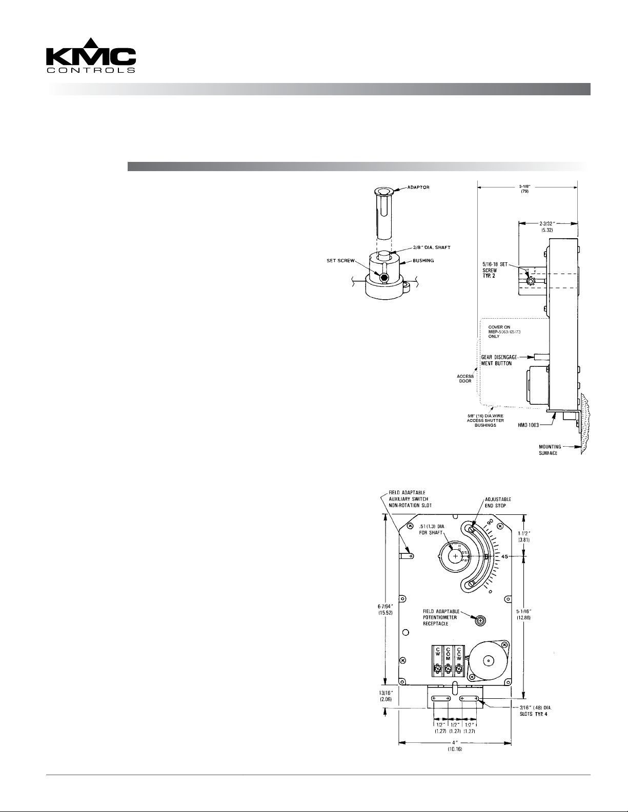
HFO-0011 Adaptor
NOTE: On a MEP-
5063/5065/5073,
access to
the gear
disengagement
buon is
through the
cover’s access
door.
MEP-5061/5063/5065/5071/5073
Actuator Side View
HFO-0011 Adaptor
1. Mount the actuator over the 3/8 in. shaft.
2. Slide the HFO-0011 over the shaft into the drive
hub of the actuator.
3. Align the adaptor slots with the set screws.
4. Partially tighten the set screws.
5. Continue with Step 2 under the Standard
Instructions section above.
MEP-5061/5063/5065/5071/5073 1 Installation Guide
Actuator Front View
Page 2
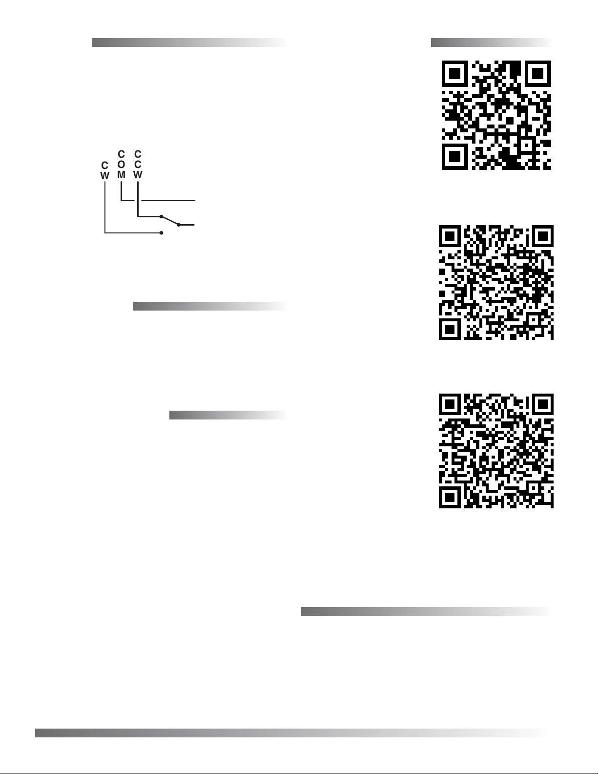
Wiring
More Information
• Connect the common to the “COM” terminal.
• Connect the clockwise 24 VAC lead to the “CW”
terminal.
• Connect the counterclockwise 24 VAC lead to the
“CCW” terminal.
CCW
COM
CW
–
24 V AC
–
Wiring Detail
~
Maintenance
No routine maintenance is required. Careful installation will also ensure long term reliability and
performance.
For specications and
list of accessories, see
the MEP-5061/5071
Data Sheet on the KMC
Controls web site.
For information about a
rotary feedback potentiometer, see the CME-
2003 Rotary Feedback
Potentiometer on the
KMC Controls web site.
Important Notices
The material in this document is for information
purposes only. The contents and the product it
describes are subject to change without notice.
KMC Controls, Inc. makes no representations or
warranties with respect to this document. In no event
shall KMC Controls, Inc. be liable for any damages,
direct or incidental, arising out of or related to the
use of this document.
For information about
auxiliary switches, see
the CME-1000 Series
Rotary Cam Auxiliary
Switches series on the
KMC Controls web site.
KMC Controls, Inc.
19476 Industrial Drive
New Paris, IN 46553
574.831.5250
www.kmccontrols.com
info@kmccontrols.com
MEP-5061/5063/5065/5071/5073 2 Installation Guide
© 2013 KMC Controls, Inc. 029-019-01xE
 Loading...