

Page 1
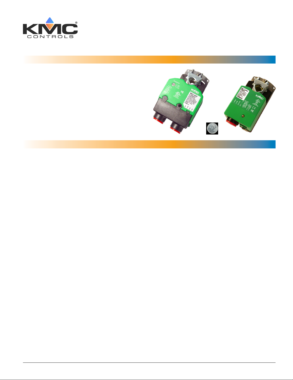
Direct-Coupled Actuators (40 to 90 in-lb.)
Applications Guide
MEP-4xxx
Contents
Introduction .................................................................................................................................... 3
Important Notices........................................................................................................................... 3
Actuator Torque Selection ............................................................................................................... 4
Heat/Cool/VAV Applications (with the CTE-5202 Thermostat) ....................................................... 4
Accessories ..................................................................................................................................... 5
Ball Joint and Crank Arms ............................................................................................................5
Enclosure, Cord Grip, and Wiring Kits ......................................................................................... 6
Mounting (Non-Rotation) Brackets .............................................................................................. 7
Thermostat ..................................................................................................................................7
Transformers ................................................................................................................................7
VEB-4x Series Valves Mounting/Repair Kits ................................................................................. 8
Troubleshooting .............................................................................................................................. 9
Auxiliary Switch Does Not Work ................................................................................................. 9
Fail-Safe Does Not Work .............................................................................................................. 9
Feedback Does Not Work ............................................................................................................ 9
No Rotation ................................................................................................................................. 9
MEP-4xxx Direct-Coupled Actuators (40 to 90 in-lb.) 1 Applications Guide, AN0513A Rev. J
Page 2

Rotation in Wrong Direction ....................................................................................................... 9
Stroke Range Is Wrong ................................................................................................................ 9
Configuration ................................................................................................................................10
Proportional (MEP-4xx2) Models Setup ..................................................................................... 10
Wiring Issues ............................................................................................................................. 10
Two-Position Wiring (MEP-4001/3/4/5) ..................................................................................... 11
Tri-State/2-Position Rotation Direction ...................................................................................... 11
Auxiliary Switch (MEP-4x2x/4x7x) ............................................................................................12
Fail-Safe Direction (MEP-42/45/49xx) ....................................................................................... 13
Index ............................................................................................................................................. 13
Specifications, design, and operation are subject to change without notice.
MEP-4xxx Direct-Coupled Actuators (40 to 90 in-lb.) 2 Applications Guide, AN0513A Rev. J
Page 3
Introduction
Important Notices
This application guide gives torque selection, accessory, troubleshooting, and other related information.
For general mounting, connection, and congura-
tion details, see the relevant model’s installation
guide. For specications and other information,
see the relevant model’s data sheet and the selection
guide. The latest support les are always available
on the KMC Controls web site (www.kmccontrols.
com):
• KMC Actuators Selection Guide
• MEP-4000/4800 Series (40/80 in-lb., proportional
or tri-state) Data Sheet and Installation Guide
• MEP-4200/4500/4900 Series (fail-safe, 25/45/90 in-
lb., proportional or tri-state/two position) Data
Sheet and Installation Guide
• MEP-4201/4501/4901 (fast operating, 25/45/90
in-lb., tri-state/two position) Data Sheet and
Installation Guide
NOTE: For sample proportional single-zone
heating/cooling valve applications using
the CTE-5202 electronic thermostat, see the
CTE-5202 Applications Guide.
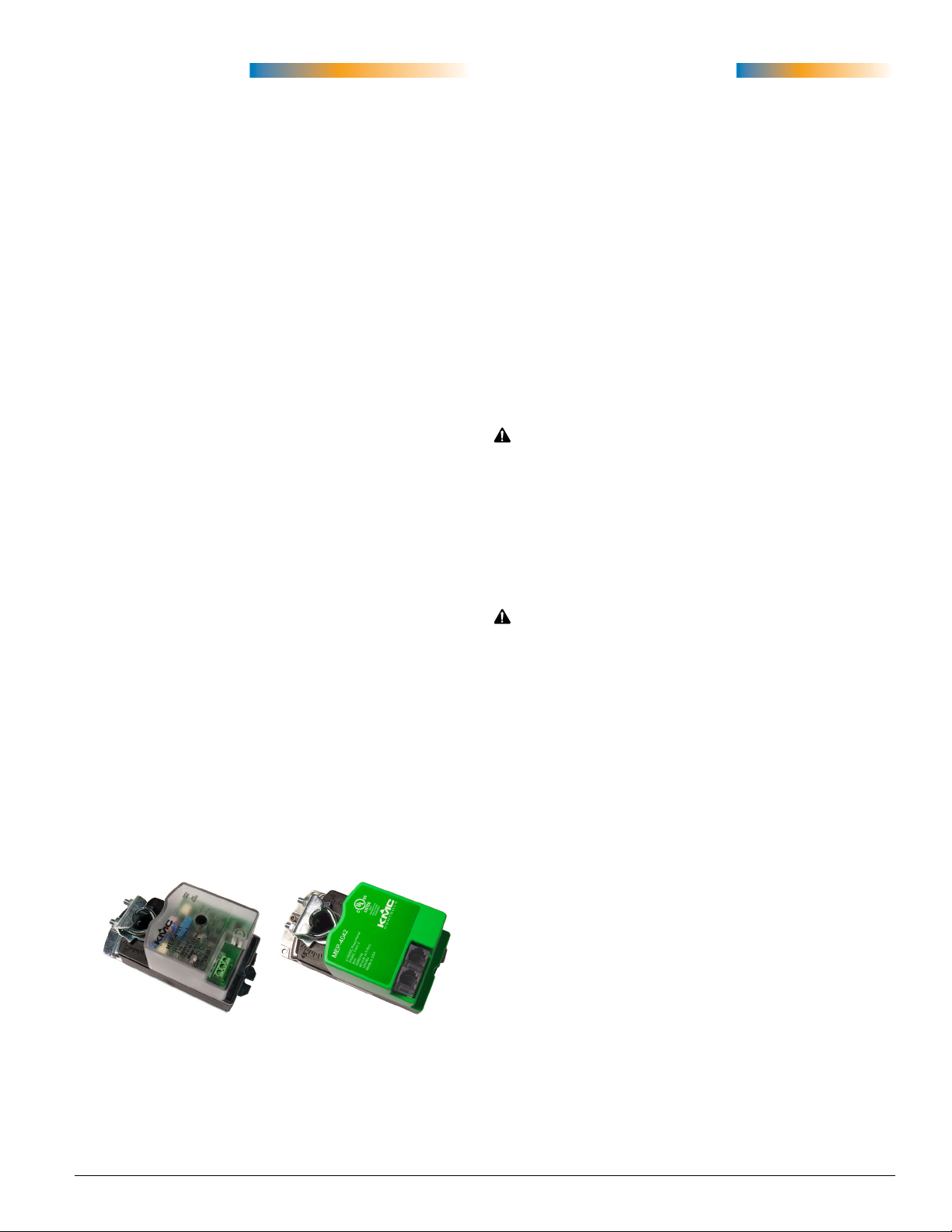
NOTE: The models MEP-4101 (tri-state, 10 in-
lb., with transluscent cover) and MEP-
4042/4842 (40/80 in-lb., proportional, with
modular connectors) are quite dierent
from the rest of the MEP-4xxx series. Also,
any particular MEP-4xxx model may
not have one or more features (e.g., failsafe, auxiliary switch) described in this
document. Use only the information from
this document that is relevant to the MEP-
4xxx model in use.
The KMC logo is a registered trademark of KMC
Controls, Inc. All rights reserved. No part of this
publication may be reproduced, transmied, transcribed, stored in a retrieval system, or translated
into any language in any form by any means without the wrien permission of KMC Controls, Inc.
The material in this document is for information
purposes only. The contents and the product it de-
scribes are subject to change without notice. KMC
Controls, Inc. makes no representations or warranties with respect to this document. In no event shall
KMC Controls, Inc. be liable for any damages, direct
or incidental, arising out of or related to the use of
this document.
WARNING
Risk of electrical shock in line-voltage models.
Disconnect ALL power before servicing. More
than one disconnect provided on models
with auxiliary switches. Failure to follow
electrical safety precautions with live electrical
components could result in injury or death.
WARNING
If both conduit connections are used in linevoltage models, they MUST be externally
connected during installation. The nonmetallic
enclosure does not provide grounding
connection between the two conduit
connections.
MEP-4xxx Direct-Coupled Actuators (40 to 90 in-lb.) 3 Applications Guide, AN0513A Rev. J
Page 4

Actuator Torque Selection
Damper manufacturers should provide information
about the required minimum actuator torque. If
by multiplying the height and width in inches and
then dividing by 144.)
that information is not available, use the following
general guidelines to calculate the required torque.
(Square feet for a rectangular duct can be calculated
Damper Type
Opposed Blades Without Seals
Parallel Blades Without Seals
Opposed Blades With Seals
Parallel Blades With Seals
Up to 1000 FPM
3 in-lb. per square foot
4 in-lb. per square foot
5 in-lb. per square foot
7 in-lb. per square foot
After minimum torque is known, see the actuator
data sheets to select the appropriate model.
1000 to 2500 FPM
4.5 in-lb. per square foot
6 in-lb. per square foot
7.5 in-lb. per square foot
10.5 in-lb. per square foot
2500 to 3000 FPM
6 in-lb. per square foot
8 in-lb. per square foot
10 in-lb. per square foot
14 in-lb. per square foot
Heat/Cool/VAV Applications (with the CTE-5202 Thermostat)
MEP-4xxx actuators can be used in single zone proportional heating (baseboard heaters) and cooling
(chilled beams) with valves or SCR control as well as
pressure-dependent VAV applications. For details of
a variety of sample applications, see the CTE-5202
Applications Guide.
(For an example of a fail-safe application on an
outside air damper, see Fail-Safe Direction (MEP-
42/45/49xx) on page 13.)
Chilled
Beam
4-Pipe
Heating
and
Cooling
Cooling Valv e
24 VAC
Common
Input
CTE-5202
Thermostat
T
AO1
AO2
AI1
T
~
24 VA C
(Neutral)
(Phase)
–
~
Pressure Dependent VAV with
Auto and Override to Fully Closed
Heating Valv e
24 VAC
Common
Input
MEP-4002
Actuator
24 VAC
Common
Out
Input
24 VA C @ 5 VA
(Neutral)
(Phase)
MEP-4xxx Direct-Coupled Actuators (40 to 90 in-lb.) 4 Applications Guide, AN0513A Rev. J
–
~
NC SPST
Relay
(Override
to Fully
Closed)
CTE-5202
Thermostat
T
AO1
AO2
AI1
T
~
(5K–10K
Ohm Resistor
between AI1
and Common
for Heating
Mode Only)
Page 5

Accessories
Ball Joint and Crank Arms
VTD-0804
Ball Joints
Crank
Arm
1/4-28X3/4"
Cap Screw
1/4-28
Hex Nut
5/16" Dia. Rod
(not included)
The HLO-4001 crank arm
kit is used when direct
mounting of the actuator
is impractical. See also the
VTD-0804 replacement
ball joint and VTD-
14xx crank arms.
(Not included)
(3) Mounting Holes
for #8 screws
(not included)
Sloed crank arms are for aaching to dampers
or other shafts, and they can be used in conjunc-
tion with the HLO-4001 crank arm kit. In the VTD1403/1404 short crank arms, an aached ball joint
(see the VTD-0804) can be adjusted from 3/4 inches
(minimum) to 2-7/8 inches (maximum) from the cen-
ter of the shaft. In VTD-1405/1406 long crank arms,
the maximum is 4-5/8 inches.
VTD-1403 Short sloed, for 3/8" shafts
VTD-1404 Short sloed, for 1/2" shafts
VTD-1405 Long sloed, for 1/2" shafts
VTD-1406 Long sloed, for 3/8" shafts
KIT INCLUDES:
(1) Crank Arm
(2) 1/4-28 X 3/4" Cap Screws
(2) 1/4-28 Hex Nuts
(2) VTD-0804 Ball Joints
Three-hole crank arms are for aaching to dampers
or other shafts, and they can be used in conjunction
with the HLO-4001 crank arm kit. An aached ball
joint (see the VTD-0804) can be 1-9/16 inches (inner
hole), 2-3/16 inches (middle hole), or 2-7/8 inches
(outer hole) from the center of the shaft.
VTD-1414 Three-hole, for 3/8" shafts
VTD-1415 Three-hole, for 1/2" shafts
The VTD-0804 replacement ball joint is for sidemounted 5/16" diameter
rods (1/4-20 male mounting stud with locknut). See
also the HLO-4001 crank
arm kit.
MEP-4xxx Direct-Coupled Actuators (40 to 90 in-lb.) 5 Applications Guide, AN0513A Rev. J
Page 6

Enclosure, Cord Grip, and Wiring Kits
The HCO-1151 enclosure kit (consisting of a metal
mounting plate, plastic cover, non-rotation bracket,
plug caps, and screws) is designed to protect actuators from inclement conditions. See also the HMO4521 liquid-tight cord grip.
An HMO-4521 liquid-tight cord grip threads into
conduit ings on MEP-4xxx actuators (except the
MEP-4003) when an ingress protection rating of
IP54 is required. The HMO-4521 accepts 0.18 to 0.40"
diameter cables. There are ve per pack. See also the
HCO-1151, HPO-4001, and HPO-4051.
An HPO-4001 assembled wiring kit has an HMO-
4521 liquid-tight cord grip, a 3-foot plenum-rated
cable, conduit ing, and a pre-wired terminal block
for the following actuators:
• MEP-4001
• MEP-4002
• MEP-4801
• MEP-4802
NOTE: It is not compatible with the MEP-40x3,
MEP-402x, MEP-4813, and MEP-482x
actuators. However, the HMO-4521 cord
grip can be installed on those models
(except for the MEP-4003) to provide IP54-
rated ingress protection.
MEP-4xxx Direct-Coupled Actuators (40 to 90 in-lb.) 6 Applications Guide, AN0513A Rev. J
An HPO-4051 assembled wiring kit has an HMO-
4521 liquid-tight cord grip, a 3-foot plenum-rated
cable, and a conduit ing for the following actuators:
• MEP-4201
• MEP-4501
• MEP-4901
• MEP-4x51
• MEP-4x52
• MEP-4x54
NOTE: It is not compatible with the MEP-4x55 and
MEP-4x7x actuators, which are pre-wired
with cables. However, the HMO-4521 cord
grip can be installed on those models to
provide IP54-rated ingress protection.
Page 7

Non-Rotation “T” Bracket (HMO–4001) Order Separately
Non-Rotation Bracket (HMO–4002) Provided
Mounting (Non-Rotation) Brackets
An HMO-4002 non-rotation bracket is provided
with MEP-40xx/48xx/425x/455x actuators (but is not
for use with MEP-427x/457x/49xx models). See also
the HMO-4001.
The HMO-4001 non-rotation “T” bracket can be used instead of the HMO-4002 to span an open distance, or
it can be formed (bent) into a shape that increases the distance between the mounting surface and the actuator. It is provided with MEP-427x/457x/49xx actuators.
The HMO-4004 non-rotation bracket kit is used for
mounting to ball valves.
9" (229 mm)
[229]
9"
3/4" (19 mm)
[19]
3/4"
Thermostat Transformers
For sample proportional single-zone heating/cooling
and pressure-dependent VAV applications using the
CTE-5202 electronic thermostat, see the CTE-5202
Applications Guide.
MEP-4xxx Direct-Coupled Actuators (40 to 90 in-lb.) 7 Applications Guide, AN0513A Rev. J
An XEE-6000 series Class-2 transformer provides 24
VAC power to the actuator:
XEE-6111-050 120 to 24 VAC, 50 VA, single-hub
XEE-6112-050 120 to 24 VAC 50 VA, dual-hub
Page 8

VEB-4x Series Valves Mounting/Repair Kits
Handle
High-Low Screws
HPO-5074
assembled on
a Valv e Body
and an MEP-
4xxxV Actuator
Cover
12 mm Screws
(VFB-4303_SX Bodies
and VEB-4303_SDL Valves)
Beaded Tie
Locking
Bail/Clip
Valve Base
15 mm Screws
(VFB-4____BX Bodies
and VEB-4____B__ Valves)
The HPO-5074 kit is for adapting valve bodies for
use with (only) “quick mounting” MEP-4xxxV actu-
ators. MEP-4xxxV actuators have an aached handle
and shaft as well as a plastic mounting bracket on
the boom of the actuator. See the relevant data
sheet for more information.
Shaft
Thermal Break
Non-Rotation Bracket
Sub Shaft
Machine Screws
Screw
Plate Mount
The HPO-5073 repair kit is designed to replace linkages on VEP-43/45/83/85 and VEB-43/46 ball valves
for use with any standard (not quick-mounting “V”
series) MEP-4xxx actuator:
• VEP-43ABB7xx through VEP-43GBB7xx
• VEP-45A1x7xx through VEP-45H4x7xx
• VEB-43/46 series ending in CK or CF
Hardware for mounting the linkage to the valve, and
the actuator to the linkage, are included with the kit.
The actuator must be ordered separately.
MEP-4xxx Direct-Coupled Actuators (40 to 90 in-lb.) 8 Applications Guide, AN0513A Rev. J
Page 9

Troubleshooting
Auxiliary Switch Does Not Work
• Check the auxiliary switch seing. See Auxiliary
Switch (MEP-4x2x/4x7x) on page 12.
• Check the wiring. (See Wiring Issues on page
10.)
Fail-Safe Does Not Work
• After initial connection or reconnection to power
on MEP-42x2/45x2/49x2 proportional models,
proper fail-safe operation might be delayed
up to 30 seconds (until the capacitors are fully
charged).
• Check the Fail-Safe Direction switch. See Fail-
Safe Direction (MEP-42/45/49xx) on page 13.
Feedback Does Not Work
• Check the feedback switch seing. See Propor-
tional (MEP-4xx2) Models Setup on page 10.
• Check the wiring. (See Wiring Issues on page
10.)
• Check that the shaft moves freely. (Press and
hold the gear disengagement lever and manually
rotate the shaft.)
• Check for a tripped circuit breaker to the trans-
former (or power supply).
• Check polarity and strength of input signal.
• Check for proper supply voltage from the trans-
former (or power supply) and that it has enough
capacity (VA) for all connected devices. See their
respective data sheets and Tips for Connecting
24-Volt Power Application Note (AN0604D).
• Check the wiring. (See Wiring Issues on page
10.)
Rotation in Wrong Direction
• For proportional models, check the position of
the direction switch (Switch 2). See Proportional
(MEP-4xx2) Models Setup on page 10.
• For tri-state and tri-state/two-position models, check the CW/CCW wiring and rotation
direction switch if applicable. See Tri-State/2-
Position Rotation Direction on page 11.
No Rotation
• After initial power-up, proportional fail-safe
MEP-42x2/45x2/49x2 actuators delay enabling
motor operation until the fail-safe capacitors are
charged. No actuator rotation will take place for
at least the rst 30 seconds.
• Check that direction switches are fully engaged
in the proper position. See Proportional
(MEP-4xx2) Models Setup on page 10 and
Tri-State/2-Position Rotation Direction on page
11.
• For fail-safe operation, check the Fail-Safe
Direction switch. See Fail-Safe Direction (MEP-
42/45/49xx) on page 13.
Stroke Range Is Wrong
• For proportional models, check the auto-
mapping. See Proportional (MEP-4xx2) Models
Setup on page 10.
• Check the adjustable stop.
• Check the voltage from the controller or thermostat.
MEP-4xxx Direct-Coupled Actuators (40 to 90 in-lb.) 9 Applications Guide, AN0513A Rev. J
Page 10

Configuration
Wiring Issues
• Check for correct wiring for the application.
• Check the wiring at the connected devices.
• Use a voltmeter and ohmmeter to check the
terminals for expected values.
• See Tips for Connecting 24-Volt Power Applica-
tion Note (AN0604D).
NOTE: Wiring must be adequate to avoid exces-
sive voltage drop on long runs! Allow
plenty of “cushion” in measurements. A
meter may be too slow to register transient dips or peaks during startup.
WARNING
Risk of electrical shock in line-voltage models.
Disconnect ALL power before servicing. More
than one disconnect provided on models
with auxiliary switches. Failure to follow
electrical safety precautions with live electrical
components could result in injury or death.
Proportional (MEP-4xx2) Models Setup
NOTE: Before Jan. 2014, MEP-40x2/48x2
proportional models had 0–10 VDC inputs
and 0–5 or 0–10 VDC feedback (only).
From 2014 through July 2015, they had
2–10 VDC inputs and 1–5 or 2–10 VDC
(only) feedback instead. Starting in August
2015, all these options were available and
selectable via a jumper and slide switch.
NOTE: Before August 2015, the MEP-
42xx/45xx/49xx fail-safe proportional
models had 2–10 VDC inputs and 1–5 or
2–10 VDC feedback (only). Starting in
August 2015, 0–10 VDC inputs and 0–5 or
0–10 VDC feedback were also available and
switch-selectable.
NOTE: When the 0–10 VDC input is selected,
selectable feedback options are 0–5 or 0–10
VDC. When the 2–10 VDC input is selected,
feedback options are 1–5 or 2–10 VDC.
For instructions in direction, feedback, and au-
tomapping, see the relevant installation guide:
WARNING
If both conduit connections are used in linevoltage models, they MUST be externally
connected during installation. The nonmetallic
enclosure does not provide grounding
connection between the two conduit
connections.
• MEP-4000/4800 Series (40/80 in-lb.) Installation
Guide
• MEP-4200/4500/4900 Series (fail-safe, 25/45/90
in-lb.) Installation Guide
MEP-4xxx Direct-Coupled Actuators (40 to 90 in-lb.) 10 Applications Guide, AN0513A Rev. J
Page 11

Two-Position Wiring (MEP-4001/3/4/5)
COM (Black)
~24 V (Red)
Tri-State/2-Position Rotation Direction
MEP-4xx4/4xx5 two-position actuators have “traditional” two wires for 24 VAC/VDC or 100–250 VAC
signal/power.
T
Power Supply
~/+
–
24 V AC/VDC
(Fail-Safe) MEP-4xx4 Two-Position 24 VAC/VDC (Two-Wire)
Starting in January 2014, tri-state MEP-4xx1/4xx3
models (except MEP-4003) also oer two-position
functionality as an option. That option is dependent
on wiring conguration and selector switch position.
See Tri-State/2-Position Rotation Direction on page
11. The (tri-state) two-position option requires
“three-wire” (non-fail-safe) or “four-wire” (fail-safe)
wiring conguration.
Tri-state/two-position MEP-4xx1/4xx3 models (except MEP-4003) have switches for selecting rotation
direction. Be sure switches are set correctly for the
application.
• Non-fail-safe MEP-4xx1/4x13 models (beginning
in Jan. 2014) have a slide switch to the right
of the terminal block. See the MEP-4000/4800
Series Installation Guide for more information.
Switch Position:
1 = Rotation is
Direct
0 = Rotation is
Reversed
Power
Supply
–
~
CW
Feedback Potentiometer
COM
CCW
(MEP-4x13 Only)
Switch Position
COM
T
CW
1 2
Contact Position:
Open = CCW Rotation
Closed = CW Rotation
CCW
–
Power Supply
24 V AC/VDC
~/+
(NFS) MEP-4x01 Two-Position Control, CW Leg (Three-Wire)
See the MEP-4201/4501/4901 Installation Guide or
MEP-4000/4800 Series Installation Guide for more
information.
Switch Position
COM
T
CW
CCW
1 2
Contact Position:
Open = CCW Rotation
Closed = CW Rotation
(FS) MEP-4x51 Two-Position Control, CW Leg (Four-Wire)
~24 V
Power Supply
~/+
–
24 V AC/VDC
MEP-4xx1/4x13 Tri-State Wiring Conguration
• Fail-safe MEP-4x51 and fast-acting MEP-4x01
models have selector switches to the left of the
terminal block. See the MEP-4200/4500/4900 Se-
ries Installation Guide or MEP-4201/4501/4901
Installation Guide for more information.
Selector
Switches
(Under Conduit Fitting)
Aux. Switch
Cable
Power/Signal
Terminal Block
Power/Signal
Cable
See the MEP-4200/4500/4900 Series Installation
MEP-42xx/45xx/49xx Options
Guide for more information.
MEP-4xxx Direct-Coupled Actuators (40 to 90 in-lb.) 11 Applications Guide, AN0513A Rev. J
Page 12

Auxiliary Switch (MEP-4x2x/4x7x)
Actuator Shown
At 45° Rotation
Rotation
Indication
(45–90°)
Auxiliary
Switch
Setting
Dial
Actuator Rotation and (MEP-497x) Auxiliary Switch Dial
Rotation
Indication
(0–45°)
Method 2 (Setting where Rotation Trips)
1. While pressing the gear disengagement lever,
rotate the actuator to the point where the
auxiliary switch should trip.
2. Using a small, at-bade screwdriver, adjust the
rotary dial to “0”. For example, if the switch is
set to trip (dial at “0”) when the actuator rotation
position is at 45°, then Red connects to Black
from 0° to 45°, and Red connects to Blue from
45° to 90°. As the actuator rotates, the switch dial
arrow points to the current switch position (Red
connected to Blue vs. Red connected to Black).
3. Wire the desired auxiliary device(s) to the cable.
NOTE: In this method, if the dial is set to “90”
instead of “0” in Step 2, switch connections
will be reversed.
NOTE: On MEP-497x models, a second switch is
xed at 10° from full CW direction (Brown
is connected to Orange in the 0–10° range,
and Brown is connected to Yellow 11–90°).
The dial adjustment has no eect on it. (The
auxiliary switch cable is the left-hand cable,
looking from the top.)
In MEP-4x2x/4x7x models, the adjustable auxiliary
SPDT switch can be set to trip anywhere between 0°
(full CW rotation position) and 90° (full CCW). To
adjust the auxiliary switch position, two dierent
methods can be followed. (Method 2 is generally
more precise.)
Method 1 (Setting Desired Dial Degrees)
1. While pressing the gear disengagement lever,
rotate the actuator to the full clockwise position
(0°).
2. Using a small, at-bade screwdriver, adjust the
rotary dial to the desired number of degrees (as
shown on the dial) at which the switch should
trip. For example, if the switch is set to trip at 45°
(dial halfway between 0° and 90° when actuator
is at full CW position), then Red connects
to Black from 0° to 45°, and Red connects to
Blue from 45° to 90°. As the actuator rotates,
the switch dial arrow points to the current
switch position (Red connected to Blue vs. Red
connected to Black).
3. Wire the desired auxiliary device(s) to the cable.
MEP-4xxx Direct-Coupled Actuators (40 to 90 in-lb.) 12 Applications Guide, AN0513A Rev. J
Page 13

Index
Fail-Safe Direction (MEP-42/45/49xx)
OAD
Fail-Safe
MEP-4xxx
24 V AC
All fail-safe MEP-42xx/45xx/49xx models oer
selectable clockwise or counterclockwise direction.
(Proportional and tri-state models also oer the option to turn the fail-safe o—usually temporarily for
test purposes.) Using a small, at-bade screwdriver,
adjust the switch dial to the desired CW/OFF/CCW
option.
BAS
Symbols
0-5/0-10 vs. 1-5/2-10 VDC Feedback: 10
0-10 vs. 2-10 VDC Inputs: 10
A
Accessories: 5
Applications: 4
Auto-Mapping: 10
Auxiliary Switch: 9, 12
B
Brackets, Non-Rotation: 7
C
Cable: 6
Conduit Fitting: 6
Configuration: 10
Cooling: 4
Cord Grip: 6
Crank Arm Kit: 5
CTE-5202: 4, 7
Fail-Safe Direction Switch Dial
NOTE: After initial connection or reconnection
to power on MEP-42x2/45x2/49x2
proportional models, proper fail-safe
operation might be delayed up to 30
seconds (until the capacitors are fully
charged).
D
Damper Torque: 4
Direction: 9, 10, 11, 12
E
Enclosure Kit: 6
F
Fail-Safe: 9, 13
Feedback: 9, 10
H
HCO-1151: 6
Heating: 4
HLO-4001: 5
HMO-4001: 7
HMO-4002: 7
HMO-4004: 7
HMO-4521: 6
HPO-4001: 6
HPO-4051: 6
HPO-5073: 8
HPO-5074: 8
I
Important Notices: 3
Inputs: 10
MEP-4xxx Direct-Coupled Actuators (40 to 90 in-lb.) 13 Applications Guide, AN0513A Rev. J
Page 14

L
T
Line Voltage Precautions: 10
M
MEP-4x01: 11
MEP-4x2x: 12
MEP-4x7x: 12
MEP-4x13: 11
MEP-4x51: 11
MEP-4xx1: 11
MEP-4xx2: 10
MEP-4xxxV: 8
MEP-40x2/48x2: 10
MEP-40xx/48xx/425x/455x: 7
MEP-42xx/45xx/49xx: 10, 13
MEP-427x/457x/49xx: 7
MEP-497x: 12
MEP-4042: 3
MEP-4101: 3
MEP-4842: 3
Mounting: 7, 8
N
Non-Rotation Brackets: 7
O
OAD (Outside Air Damper): 13
P
Thermostat: 7
Torque Selection: 4
Transformers: 7
Tri-State/Two-Position: 11
Troubleshooting: 9
Two-Position Wiring: 11
Two-Wire vs. Three-Wire vs. Four-Wire for Two-Posi-
tion: 11
V
V Actuators: 8
Valves: 4, 8
Valves Mounting: 7, 8
VAV: 4
Voltage, Line, Precautions: 10
VTD-14xx: 5
VTD-0804: 5
W
Warnings: 10
Weather Shield Enclosure Kit: 6
Web Site: 3
Wiring: 10, 11
Wiring Kits: 6
X
XEE-6000 Series: 7
Proportional: 9, 10
Q
Quick-Mount MEP-4xxxV: 8
R
Rotation: 9, 11, 12
S
Stroke Range: 9
Support Files: 3
Switches
Auxiliary: 9, 12
Fail-Safe Direction: 9, 13
Feedback Voltage: 9
Rotation Direction: 9, 11
MEP-4xxx Direct-Coupled Actuators (40 to 90 in-lb.) 14 Applications Guide, AN0513A Rev. J
© 2017 KMC Controls, Inc. AN0513A Rev. J
KMC Controls
19476 Industrial Drive
New Paris, IN 46553
574.831.5250
Fax 574.831.5252
www.kmccontrols.com
info@kmccontrols.com
 Loading...