

Page 1
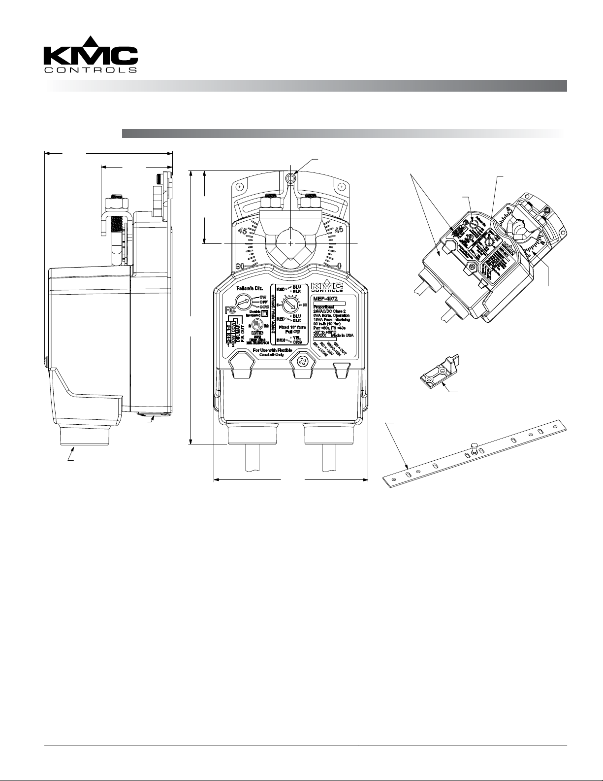
Mounting
2.812
(71.4)
1.563
(39.7)
Fail-Safe, Direct-Coupled Actuators (25/45/90 in-lb.)
MEP-4200/4500/4900 Series
Installation Guide
Adjustable
Stop
1.625
(41.3)
6.000
(152.4)
Remove Conduit Cover to
Access Selector Switches
Fail Direction
Switch
3-Foot Cables
(Some Models)
Adjust. Auxiliary
Switch Dial
° Rotation
Indicators
Gear
Disengagement
Lever
Removeable Conduit Fitting with
(2)1/2" NPS Threaded Holes (for
use with flexible conduit only)
Illustration 1—Overview (Direct-Coupled Mounting)
1. Ensure the damper can move freely through its
entire range of motion, and x any binding before
installing the actuator. Turn the damper blade to
its fully closed position.
2. Press (to the right) and hold the gear disengagement lever (see Illustration 1), rotate the actuator
to the fully closed position, and release the lever.
NOTE: Depending on the damper-seal design,
backing the actuator o its stop
approximately 5° may provide tight
damper shut-o.
3. Align the actuator and slide it onto the shaft.
4. Leaving a gap between the actuator and
mounting surface to prevent any binding, ngertighten the nuts on the V-bolt.
HMO-4002 Non-Rotation
Bracket included with
MEP-425x/455x Models
HMO-4001 Non-Rotation “T”
Bracket included with
MEP-4x7x/49xx Models
3.406
(86.5)
5. Insert the provided (HMO-4001/4002, dependent
on model) non-rotation bracket into the slot at the
base of the actuator and secure the non-rotation
bracket with two #8 or #10 self-tapping screws.
6. Evenly tighten the V-bolt nuts (30–35 in-lb.
on MEP-42xx models or 60–70 in-lb. on MEP45xx/49xx models).
7. If desired, use a 7/64-inch hex key wrench to
loosen and position the end-stop screw.
NOTE: The two holes at the top of the actuator
are NOT for use in direct-coupled
applications. (They are for remote
mounting, such as with the optional
HLO-4001 Crank Arm Kit.) For mounting
to valves, see the appropriate valve
installation guide.
MEP-4200/4500/4900 Series 1 Installation Guide
Page 2
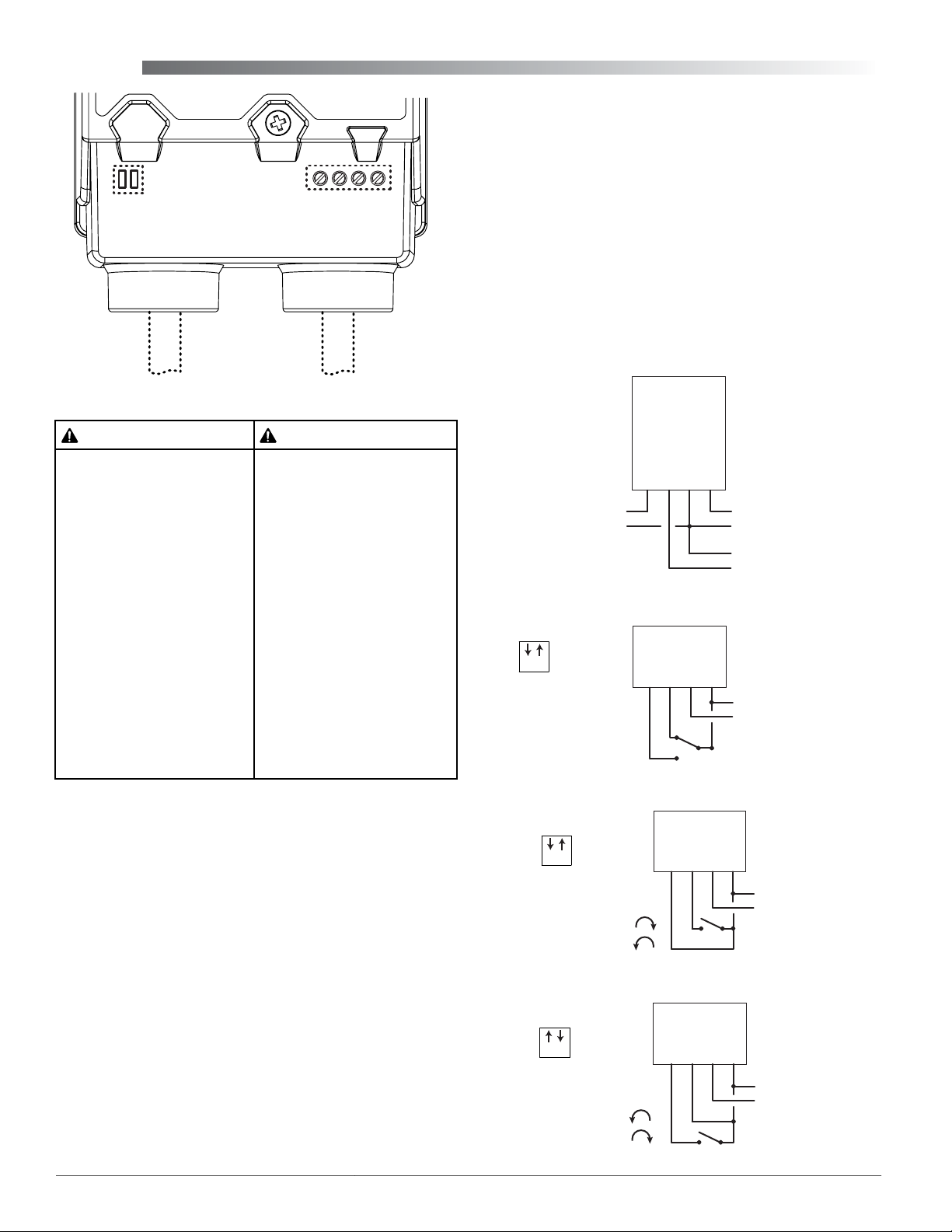
Wiring
Selector
Switches
(Under Conduit Fitting)
Power/Signal
Terminal Block
3. Thread wires through the plugged opening and
connect to the terminal block according to the
relevant model and application.
4. For MEP-4xx2 models, adjust the feedback
voltage, direction, and automapping as needed.
See Direction, Feedback, and Auto-Mapping
(MEP-4xx2) on page 4. For MEP-4x51
models, adjust the selector switch as shown in
Illustrations 2 and 4–6.
5. Reinstall the conduit ing and tighten the screw.
Aux. Switch
Cable
Power/Signal
Cable
Illustration 2—Cables and Terminal Block Options
CAUTION ATTENTION
Risk of electrical shock.
Disconnect ALL power
before servicing. More than
one disconnect provided
on models with auxiliary
switches. Failure to follow
electrical safety precautions
with live electrical
components could result in
injury or death.
If both conduit connections
are used, they MUST be
externally connected during
installation. The nonmetallic
enclosure does not provide
grounding connection
between the two conduit
connections.
Depending on the model, signal/power wiring might
be to terminals under the conduit ing or to color-
coded wires in the aached cable. See Illustration 2.
Consult the model label and the appropriate wiring
shown in Illustrations 3 through 8.
For auxiliary switch wiring and seing, see Auxil-
iary Switch (MEP-4x7x) on page 3.
For models withOUT the aached signal/power
cable:
Risque de choc électrique.
Débranchez l’alimentation
avant l’entretien. Plus d’un
sectionneur fourni sur les
modèles avec contacts
auxiliaires. L’inobservation
des consignes de sécurité
électrique avec des
composants électriques sous
tension peut entraîner des
blessures ou la mort.
Si les deux entrées de câble
sont utilisés, ils doivent être
connectés en externe lors de
l’installation. Le boîtier nonmétallique n’assure pas la
connexion à la terre entre les
deux connexions.
NOTE: After initial power-up, proportional models
have a 30-second delay of motor operation.
COM (Black)
T
OUT (Green)
2–10 IN (White)
~24 V (Red)
Feedback Output
1–5 or 2–10 VDC
+
–
Illustration 3—MEP-4xx2 Proportional Control
1 2
Switch
Position
CW
CCW
–
T
COM
Illustration 4—MEP-4x51 Tri-State Floating Point Control
Switch Position
T
CW
1 2
Contact Position:
Open = CW Rotation
Closed = CCW Rotation
CCW
Illustration 5—MEP-4x51 2-Position Control (4-Wire), CCW Leg
~/+
–
–
+
~24 V
~/+
–
COM
~24 V
Power Supply
24 VAC/VDC
Control Signal
2–10 VDC
Power Supply
24 VAC/VDC
Power Supply
~/+
–
24 VAC/VDC
1. Loosen the screw on the conduit ing and lift up
to remove the ing.
2. Using a utility knife or drill, cut the red plug
to accept wiring or replace the plug with an
application-specic ing.
NOTE: The red plug (or similar ing) protects
internal components from debris, helping
to ensure long actuator life.
MEP-4200/4500/4900 Series 2 Installation Guide
Switch Position
COM
T
CW
CCW
1 2
Contact Position:
Open = CCW Rotation
Closed = CW Rotation
~24 V
Power Supply
~/+
–
24 VAC/VDC
Illustration 6—MEP-4x51 2-Position Control (4-Wire), CW Leg
Page 3

(L1) Neutral (Black)
(L2) Line (Red)
T
COM (Black)
~24 V (Red)
Power Supply
~/+
–
24 VAC/VDC
Illustration 7—MEP-4xx4 Two-Position (2-Wire) 24 VAC/VDC
NOTE: Double Insulated. Meets UL
requirements without the need
of an electrical ground connection.
Line/Hot
Neutral
100–240 VAC Power
Illustration 8—MEP-4xx5 Two-Position (2-Wire) 100–240 VAC
actuator rotates, the switch dial arrow will point
to the current switch position (Red connected to
Blue vs. Red connected to Black). For example,
if the switch is set to trip (dial at “0”) when the
actuator rotation position is at 45°, then Red is
connected to Black from 0° to 45°, and Red is
connected to Blue from 45° to 90°.
NOTE: On MEP-497x models, a second switch is
xed at 10° from full CW direction (Brown
is connected to Orange in the 0–10° range,
and Brown is connected to Yellow 11–90°).
3. Wire the desired auxiliary device(s) to the cable.
NOTE: For more detailed information, see the
MEP-4xxx Application Guide on the KMC
web site.
NOTE: The SPDT switch is rated for 6 A with resis-
tive load or 3 A with motor load @ 250 VAC.
Auxiliary Switch Cable*
Wire Color Function
Fail-Safe Direction
All models oer selectable fail-safe direction. Proportional and tri-state models also oer the option
to turn the fail-safe o (see Illustration 9). Using a
small, at-bade screwdriver, adjust the switch dial to
the desired clockwise or counterclockwise direction.
Illustration 9—Fail-Safe Direction Switch Dial
NOTE: After initial connection or reconnection to
power on MEP-4xx2 proportional models,
proper fail-safe operation might be delayed
up to 30 seconds (until the capacitors are
fully charged).
Auxiliary Switch (MEP-4x7x)
In MEP-4x7x models, the adjustable auxiliary SPDT
switch can be set to trip anywhere between 0° (full
CW rotation position) and 90° (full CCW). To adjust
the auxiliary switch position:
Red Adjustable Aux. Switch, Common
Blue Adjustable Aux. Switch (see Illustration 10)
Black Adjustable Aux. Switch (see Illustration 10)
Brown** Fixed Aux. Switch, Common
Orange** Fixed Aux. Switch, Closed 0–10°
Yellow** Fixed Aux. Switch, Closed 11–90°
*Left-hand cable, looking from the top (see Illustration 2).
**Fixed auxiliary switches (with brown, yellow, orange wires) are
only available in MEP-497x models.
Actuator Shown
At 45° Rotation
Rotation
Indication
(45–90°)
Auxiliary
Switch
Setting
Dial
Rotation
Indication
(0–45°)
1. While pressing the gear disengagement lever (see
2. Using a small, at-bade screwdriver, adjust the
MEP-4200/4500/4900 Series 3 Installation Guide
Illustration 1), rotate the actuator to the point
where the auxiliary switch should trip.
rotary dial to “0” (see Illustration 10). As the
Illustration 10—Actuator Rotation and (MEP-497x) Aux. Switch
Page 4

Direction, Feedback, and Auto-Mapping (MEP-4xx2)
MEP-4xx2 proportional models oer selectable
actuator direction and selectable proportional feedback of 1–5 VDC or 2–10 VDC (in either direction).
To access the selector switches, loosen the (2)
screws on the conduit ing and lift up to remove
the ing. The selector switches are shipped from
the factory in the 1–5 VDC (#1 pushed Up) and
CW movement with increasing voltage (#2 pushed
Down) positions (see Illustration 11).
Switch (#1) Feedback (#2)* Direction
Up 1–5 VDC CCW
Down 2–10 VDC CW
Illustration 11—Feedback/Direction/Mapping Selectors
*NOTE: Selector Switch #2 has two functions:
1. Switch #2 determines the direction to rotate
(CW or CCW) with increasing voltage and
is factory set in the CW position (down). To
change, remove power before ipping the
switch up to the CCW position. Removing
power prevents initiation of the auto-mapping
feature.
2. Switch #2 initiates the auto-mapping
feature. (See description below.) This feature
is initiated only by cycling the switch with
power applied to the unit. The auto-mapping
feature will NOT begin if the switch position is
changed with power removed or in the event
of a power failure.
3. Return selector switch #2 to the required
increasing voltage direction before the reset
nishes. The reset process is complete after the
actuator has moved to the CW limit and has
begun to position normally.
4. Verify that the actuator travels completely across
the new range.
NOTE: For example, after completing the auto-
mapping program, the new actuator stroke
is 0–80°. A 6 VDC input signal (halfway
between 2–10 VDC) will then drive the
actuator to the 40° position (50% of its
adjusted range) and the feedback voltage
will be 3 VDC if switch #1 is set at the 1–5
VDC position or 6 VDC if switch #1 is set at
2–10 VDC.
Maintenance
No routine maintenance is required. Careful
installation will ensure long term reliability and
performance.
More Information
For models, specications,
and additional information,
see the MEP-4200/4500/4900
Series Data Sheet on the
KMC web site.
MEP-4xx2 models also oer a actuator/signal range
reset program (auto-mapping) feature that reassigns
the full 2–10 VDC input signal scale over a reduced
stroke range for more precise control.
NOTE: The auto-mapping feature works best for
ranges that are more than about 45°.
To set the auto-mapping:
1. If desired, use a 7/64-inch hex key wrench to
loosen and position the end-stop screw.
2. After power has been applied to the actuator for
at least 30 seconds (allowing fail-safe capacitors to
charge), ip selector switch #2 (from its required
CW or CCW increasing voltage direction) to start
the reset mode. The actuator will rst move to the
CCW limit. The complete reset process will take
approximately four minutes.
MEP-4200/4500/4900 Series 4 Installation Guide© 2014 KMC Controls, Inc. 039-019-01G
For accessories, troubleshooting, torque selection,
links to sample applications, and other information, see the MEP-4xxx
Applications Guide on the
KMC web site.
KMC Controls, Inc.
19476 Industrial Drive
New Paris, IN 46553
574.831.5250
www.kmccontrols.com
info@kmccontrols.com
 Loading...