

Page 1
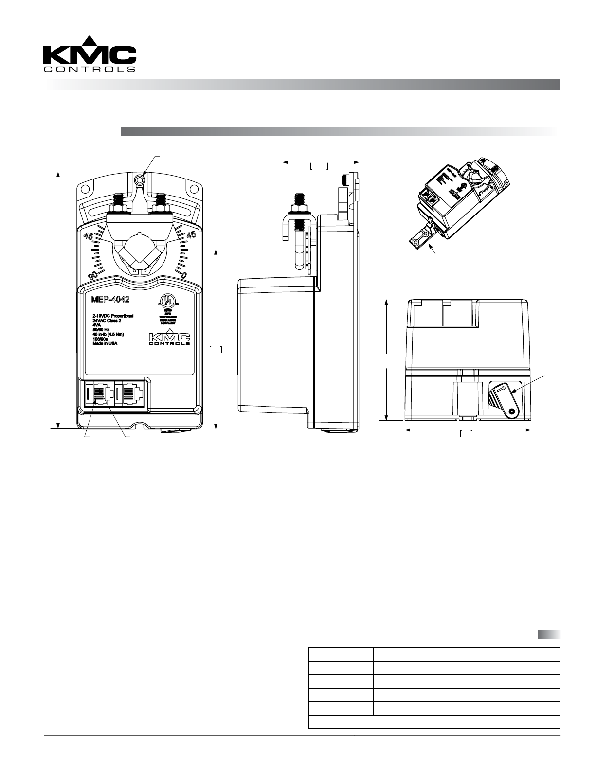
Mounting
Direct-Coupled ControlSet® Actuators (40/80 in-lb.)
MEP-4042/4842
Installation Guide
5.300
[135]
PIN 1
PIN 6
ADJUSTABLE
STOP
3.700
94
1.568
39.8
2.500
[63.5]
NON-ROTATION BRACKET
PROVIDED (HMO-4002)
GEAR DISENGAGEMENT
2.600
66
LEVER
1. Ensure the damper can move freely through its
entire range of motion, and x any binding before
installing the actuator. Turn the damper blade to
its fully closed position.
2. Press (to the right) and hold the gear
disengagement lever (see the illustration above),
rotate the actuator to the fully closed position,
and release the lever.
NOTE: Depending on the damper-seal design,
backing the actuator o its stop
approximately 5° may provide tight
damper shut-o.
3. Align the actuator and slide it onto the shaft.
4. Leaving a gap between the actuator and
mounting surface to prevent any binding, ngertighten the nuts on the V-bolt.
5. Insert the non-rotation bracket (HMO-4002
supplied or HMO-4001 “T” bracket available
separately) into the slot at the base of the actuator.
(See the illustration above).
6. Secure the non-rotation bracket with two (2) #8 or
#10 self-tapping screws.
7. Evenly tighten the V-bolt nuts 30 to 35 in-lbs. on
the MEP-4042, or 60 to 70 in-lbs. on the MEP-4842.
8. If desired, use a 7/64-inch hex key wrench to
loosen and position the end-stop screw.
NOTE: The two holes at the top of the actuator
are NOT for use in direct-coupled
applications. They are for remote mounting,
such as with the optional HLO-4001 Crank
Arm Kit (see the installation guide for the
MEP-4000/4800 series actuators).
Connector Pin Voltage Reference
Connector Pins* Function
1 and 6 ~ 24 VAC (phase side)
2 and 5 Common
3 17.4 VDC out @ 10 mA Max. (powers CTE-5201-16)
4 Signal input (2–10 VDC)
*See the pin designators in the lower left of the illustration above.
MEP-4042/4842 1 Installation Guide
Page 2
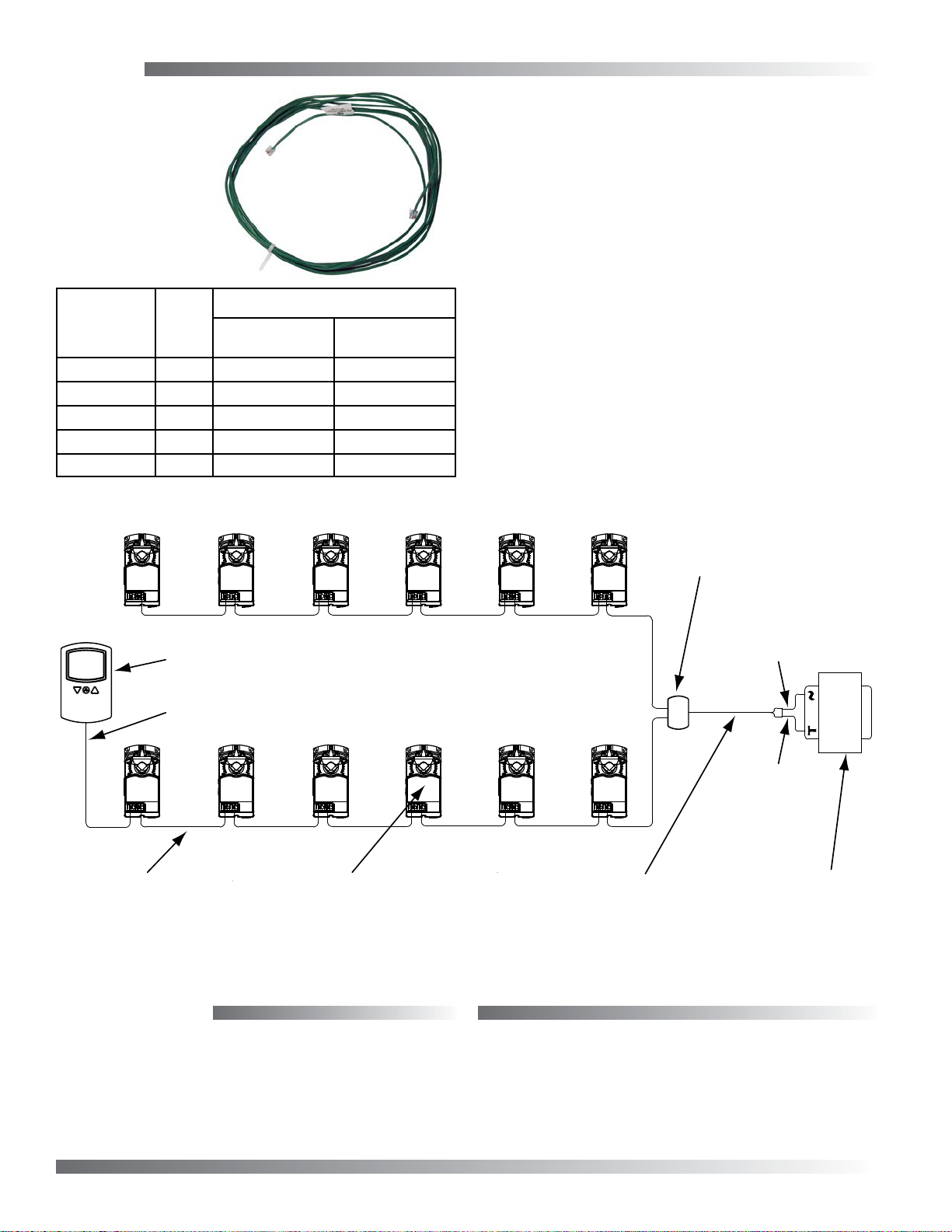
Wiring
Use HSO-22xx
cables to connect
the actuators,
using the modular
connectors, as
shown in the
chart and sample
application below.
Cable P/N
HSO-2203 3 feet 6 12
HSO-2206 6 feet 6 12
HSO-2212 12 feet 6 12
HSO-2220 20 feet 4 8
HSO-2250 50 feet 2 4
Cable
Length
Max. # of Daisy-Chained MEP-4x42s
WithOUT
HSO-5010
WITH
HSO-5010
NOTE: The transformer must have an internal
circuit breaker such as the XEE-6311-050
or equivalent 2.25 A external fuse in the
secondary circuit!
NOTE: See the table on the left for the maximum
number of actuators that may be daisy
chained for a given cable length. If an
HSO-5010 “Y” connector is used (as shown
below), the total number of actuators is
doubled (with half on each side of the
transformer). The example below shows
12 actuators with HSO-2212 cables and an
HSO-5010.
NOTE: For MEP-4042/4842 specications,
accessories, and additional important
information, see the data sheet. See also the
sample applications in the data sheets for
the BAC-5841/5842 and BAC-5841-16/5842-
16 of controllers.
HSO-5010 3-Way
“Y” Modular Connector
CTE-5201-16 Analog Electronic Thermostat
HSO-2250 Thermostat Cable, 50-foot (typical)
HSO-2212
actuator cable,
12-foot length
between actuators
Up to 6 MEP-4x42s
on each side
of the transformer
(with HSO-2212s)
Maintenance
No routine maintenance is required. The motors
are permanently lubricated and all internal geartrain components are oil-impregnated. Careful
installation will also ensure long term reliability and
performance.
Wires: Orange
& Orange Stripe
T
Wires: Green
& Green Stripe
HSO-2121
Transformer Cable
XEE-6xxx-xxx
Transformer
24 VAC (+20/–15),
4 VA Per Actuator
KMC Controls, Inc.
19476 Industrial Drive
New Paris, IN 46553
574.831.5250
www.kmccontrols.com; info@kmccontrols.com
MEP-4042/4842 2 Installation Guide© 2013 KMC Controls, Inc. 036-019-02xB
 Loading...