

Page 1
Mounting
Direct-Coupled ControlSet® Actuators (40/80 in-lb.)
MEP-4000/4800 Series
Installation Guide
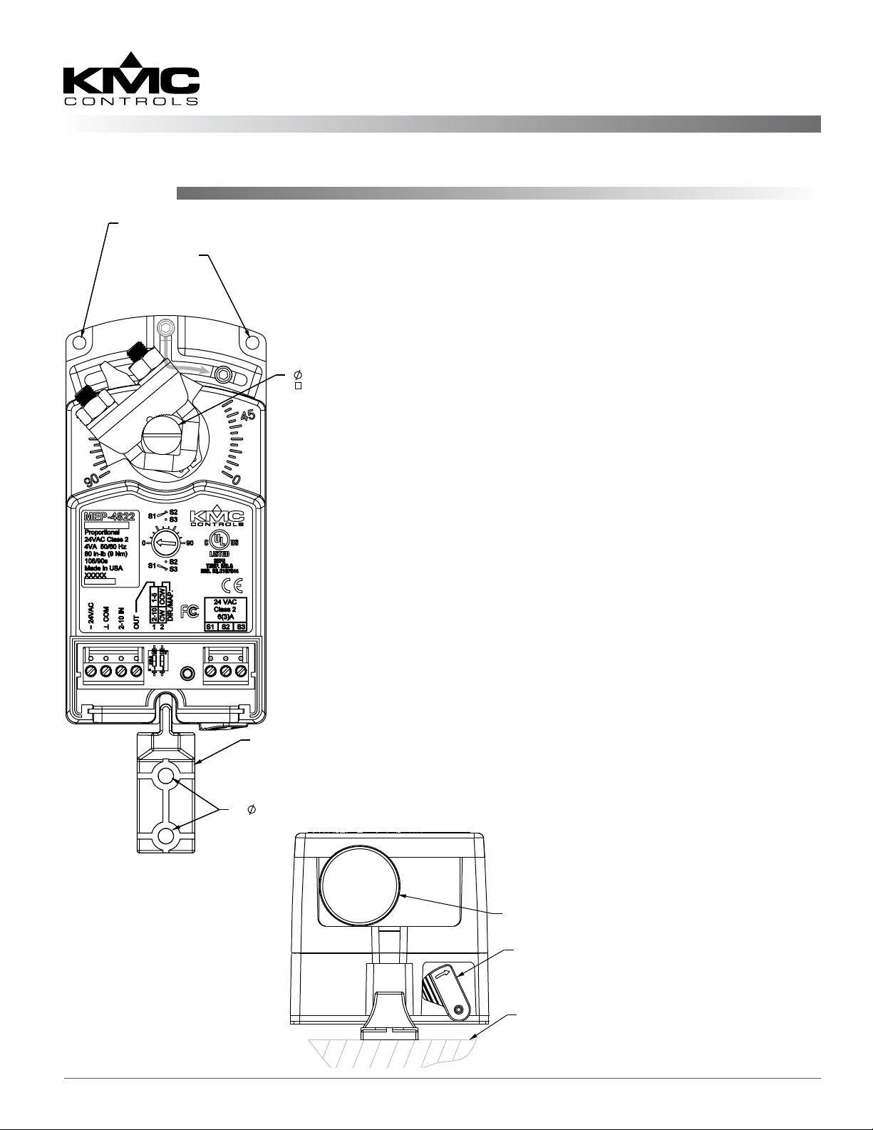
THESE HOLES ARE FOR USE IN
REMOTE MOUNTING SITUATIONS—
DO NOT USE IN DIRECT COUPLED
APPLICATIONS
ADJUSTABLE
END STOP
1/4" to 5/8" (6 to 16mm)
1/4" to 7/16" (6 to 11mm)
1. Ensure the damper can move freely through its
entire range of motion, and x any binding before
installing the actuator. Turn the damper blade to
its fully closed position.
2. Press (to the right) and hold the gear
disengagement lever (see Illustration 1), rotate the
actuator to the fully closed position, and release
the lever.
NOTE: Depending on the damper-seal design,
backing the actuator o its stop
approximately 5° may provide tight
damper shut-o.
3. Align the actuator and slide it onto the shaft.
4. Leaving a gap between the actuator and
mounting surface to prevent any binding, ngertighten the nuts on the V-bolt.
5. Insert the non-rotation bracket (HMO-4002
supplied or HMO-4001 “T” bracket available
separately) into the slot at the base of the actuator.
(See Illustration 1).
6. Secure the non-rotation bracket with two (2) #8 or
#10 self-tapping screws.
7. Evenly tighten the V-bolt nuts 30–35 in-lb. on
MEP-4000s or 60–70 in-lb. on MEP-4800s.
8. If desired, use a 7/64-inch hex key wrench to
NON-ROTATION BRACKET
(HMO-4002)
loosen and position the end-stop screw.
NOTE: The two holes at the top of the actuator
are NOT for use in direct-coupled
(2)
0.200 (5mm)
applications. They are for remote
mounting, such as with the optional HLO4001 Crank Arm Kit (see the MEP-4000/4800
Series Data Sheet).
REMOVEABLE CONDUIT FITTING
Illustration 1—Overview
(Direct-Coupled Mounting)
MEP-4000/4800 Series 1 Installation Guide
WITH 1/2" NPS THREADED HOLE
GEAR
DISENGAGEMENT
LEVER
MOUNTING
SURFACE
Page 2

Wiring
NOTE: Before January 2014, MEP-40x2/48x2
models had 0–10 VDC inputs. They now
have 2–10 VDC inputs. When replacing
an older 0–10 VDC actuator with a 2–10
VDC actuator, congure the connected
controller or thermostat output to match.
See the model number on the actuator label and the
relevant wiring illustration (2 through 5).
MEP-4003 Only
NOTE: The MEP-4003’s terminals are not enclosed
inside the case as the other models are.
1. Route the cable through the strain relief molded
in the lower left of the case. (See Illustration 2.)
2. Connect the wires to the terminal block.
feedback voltage as needed. See Illustration 5 and
Direction, Feedback, and Auto-Mapping (MEP4xx2) on page 3.
8. For MEP-4xx1/4x13s, adjust rotation direction
switch if needed (see Illustration 3 and 4).
9. Reinstall the tethered cover and tighten the screw.
Switch Position:
1 = Rotation is
Direct
0 = Rotation is
Reversed
–
Power
Supply
~
Illustration 3—MEP-4xx1/4x13 TRI-STATE Wiring
CW
Feedback Potentiometer
COM
CCW
(MEP-4x13 Only)
Strain Relief
Power
–
Supply
~
Illustration 2—MEP-4003 (Only) Wiring
All Except MEP-4003
1. Loosen the screw on the tethered access cover and
remove the cover.
2. Slide the conduit ing plate out.
3. Using a utility knife or drill, cut the red plug
to accept wiring or replace the plug with an
application-specic ing.
NOTE: The red plug (or similar ing) protects
internal components from debris, helping to
ensure long actuator life.
4. Thread wires through the plugged opening and
connect to the terminal block. (See Illustrations 3
through 5.)
NOTE: For your convenience, the wiring terminal
block is removable.
Switch Position:
1 = Rotation is
Direct
0 = Rotation is
Reversed
Power
–
Supply
~
Contact Position: Open = CW Rotation, Closed = CCW Rotation
Illustration 4—MEP-4xx1/4x13 2-POSITION (3-Wire) Wiring
CW
Feedback Potentiometer
COM
CCW
(MEP-4x13 Only)
5. Connect and adjust the auxiliary switch if
required (MEP-4x2x only). See Auxiliary Switch
(4x2x) on page 4.
6. Reinstall the terminal block on the pins (if
removed) and the conduit ing plate.
7. For MEP-4xx2 (proportional) models, adjust the
auto-mapping range reset, rotation direction, and
MEP-4000/4800 Series 2 Installation Guide
Power
~
–
Supply
Control Signal
2–10 VDC
Illustration 5—MEP-4xx2 Proportional Wiring
–
+
+
Feedback Output
–
1–5 or 2–10 VDC
Page 3

Direction, Feedback, and Auto-Mapping (MEP-4xx2)
NOTE: Before Jan. 2014, MEP-40x2/48x2 models
had 0–10 VDC inputs and 0–5 or 0–10
VDC feedback instead. When replacing an
older 0–10 VDC actuator with a 2–10 VDC
actuator, make note of the dierences.
MEP-4xx2 proportional models oer selectable
actuator direction and selectable proportional feedback of 1–5 VDC or 2–10 VDC (in either direction).
To access the selector switches, loosen the screw on
the tethered cover and remove the cover. The selec-
tor switches are shipped from the factory in the 1–5
VDC (#1) and CW movement with increasing voltage
(#2) positions (see Illustration 6).
MEP-4xx2 models also oer a actuator/signal range
reset program (auto-mapping) feature that reassigns
the full 2–10 VDC input signal scale over a reduced
stroke range for more precise control.
NOTE: The auto-mapping feature works best for
ranges that are more than about 45°.
To set the auto-mapping:
1. If desired, use a 7/64-inch hex key wrench to
loosen and position the end-stop screw.
2. With power applied to the actuator, ip selector
switch #2 (from its required CW or CCW
increasing voltage direction) to start the reset
mode. The actuator will rst move to the CCW
limit. The complete reset process will take
approximately four minutes.
3. Return selector switch #2 to the required
increasing voltage direction before the reset
nishes. The reset process is complete after the
actuator has moved to the CW limit and has
begun to position normally.
Switch (#1) Feedback (#2)* Direction
Up 1–5 VDC CCW
Down 2–10 VDC CW
Illustration 6—Feedback/Direction/Mapping Selectors
*NOTE: Selector Switch #2 has two functions:
1. Switch #2 determines the direction to rotate
(CW or CCW) with increasing voltage and is
factory set in the CW position (down). To
change, remove power before ipping the
switch up to the CCW position. Removing
power prevents initiation of the auto-mapping
feature.
2. Switch #2 initiates the auto-mapping
feature. (See description below.) This feature
is initiated only by cycling the switch with
power applied to the unit. The auto-mapping
feature will NOT begin if the switch position is
changed with power removed or in the event
of a power failure.
4. Verify that the actuator travels completely across
the new range.
For example, after completing the auto-mapping
program, the new actuator stroke is 0–80°:
• For current (starting Jan. 2014) MEP-40x2/48x2
actuators, a 6 VDC input signal (halfway between
2–10 VDC) will drive the actuator to the 40°
position (50% of its adjusted range) and the
feedback voltage will be 3 VDC if switch #1 is set
at the 1–5 VDC position or 6 VDC if switch #1 is
set at 2–10 VDC.
• For older (before 2014) MEP-40x2/48x2 actuators,
a 5 VDC input signal (halfway between 0–10
VDC) will drive the actuator to the 40° position
(50% of its adjusted range) and the feedback
voltage will be 2.5 VDC if switch #1 is set at the
0–5 VDC position or 5 VDC if switch #1 is set at
0–10 VDC.
NOTE: For more information (including
adjustments, accessories, troubleshooting,
torque selection, and links to sample
applications), see the MEP-4xxx
Applications Guide on the KMC web site.
MEP-4000/4800 Series 3 Installation Guide
Page 4

Auxiliary Switch (4x2x)
In MEP-4x2x models, the adjustable auxiliary SPDT
switch can be set to trip anywhere between 0° (full
CW rotation position) and 90° (full CCW). To adjust
the auxiliary switch position, two dierent methods
can be followed. (Method 2 is generally slightly more
precise.)
Method 1
1. While pressing the gear disengagement lever
(see Illustration 1), rotate the actuator to the full
clockwise position (0°).
2. Using a small, at-bade screwdriver, adjust the
rotary dial to the desired number of degrees (as
shown on the dial) at which the switch should
trip. For example, if the switch is set to trip at 45°
(dial halfway between 0° and 90° when actuator
is at full CW position), then S1 is connected to
S2 from 0° to 45°, and S1 is connected to S3 from
45° to 90°. As the actuator rotates, the switch dial
arrow will point to the current switch position (S1
connected to S2 vs. S1 connected to S3).
Actuator Shown
At 45° Rotation
Rotation
Indication
(45–90°)
Illustration 7—Auxiliary Switch Dial and Terminal Block
Rotation
Indication
(0–45°)
Maintenance
No routine maintenance is required. Careful
installation will also ensure long term reliability and
performance.
3. Connect the auxiliary unit to the terminal block
(see Illustration 7).
Method 2
1. While pressing the gear disengagement lever,
rotate the actuator to the point where the
auxiliary switch should trip.
2. Using a small, at-bade screwdriver, adjust the
rotary dial to “0”. For example, if the switch is
set to trip (dial at “0”) when the actuator rotation
position is at 45°, then S1 is connected to S3 from
0° to 45°, and S1 is connected to S2 from 45° to
90°. As the actuator rotates, the switch dial arrow
will point to the current switch position (S1
connected to S2 vs. S1 connected to S3).
3. Connect the auxiliary unit to the terminal block
(see Illustration 7).
NOTE: The SPDT switch is rated for 6 A with
resistive load or 3 A with motor load @ 250
VAC.
More Information
For specications and other
information, see the MEP-
4000/4800 Series Data Sheet
on the KMC web site.
For adjustments, accessories, troubleshooting, torque
selection, links to sample
applications, and other
information, see the MEP-
4xxx Applications Guide on
the KMC web site.
KMC Controls, Inc.
19476 Industrial Drive
New Paris, IN 46553
574.831.5250
www.kmccontrols.com
info@kmccontrols.com
MEP-4000/4800 Series 4 Installation Guide© 2014 KMC Controls, Inc. 036-019-01H
 Loading...