

Page 1

ControlSet® MEP-455 Series Spring Return
Rotary Electronic Damper Actuator
a. Actuator
b. Self-centering shaft
adapter
c. Position indicator
d. Shaft adapter
h
locking clip
a
EA0322R2
b
d
e
c
Figure 1. Parts of the MEP-455 Actuator.
g
f
Installation Instructions
Document No. 129-361
August 3, 2004
e. Position indicator
adapter
f. Mounting bracket
g. Mounting screws
h. 3 mm hex wrench
Product Description
These installation instructions describe the steps for
direct-coupled mounting of the ControlSet MEP-455
Spring Return Electronic Damper Actuators.
Product Numbers
MEP-455xxx
Warning/Caution Notations
WARNING:
CAUTION:
Personal injury or loss of life
may occur if you do not
perform a procedure as
specified.
Equipment damage or loss of
data may occur if you do not
follow a procedure as
specified.
Required Tools
• 10 mm (13/32-inch) open end wrench
• Drill
• 4 mm (5/32-inch) drill bit
• 3 mm hex wrench (provided)
• Phillips screwdriver
• Marker or pencil
Mounting Positions
NEMA 2
˚
<
90
˚
EA0692R1
Figure 2. Acceptable NEMA 2 Positions.
˚
90
<
90
Prerequisites
NOTE: The actuator is shipped from the factory with
5° preload. When power is applied to the
actuator, the preload is released.
To manually release the preload, insert the 3 mm
hex key in the override opening and turn the key in
the direction of the arrow. See Manual Override.
WARNING:
Do not open the actuator.
Expected Installation Time
30 minutes
Item Number 129-361-02, Rev. 011 Page 1 of 7
Page 2

Document No. 129-361
Installation Instructions
August 3, 2004
Installation
1
3
>
77 mm
>3 in
>20 mm
>3/4 in
<
77 mm
<3 in
90°
2
EA0327R1
2
Figure 3. Actuator Mounting Orientation.
d
5
b
4
a
ADAPTER
d
ALIGNMENT
5
b
4
a
6
e
SHAFT
MARK
90°
c
c
c
c
6
6
90
c
c
7
7
Page 2 of 7
EA0370R2
Figure 4. Shaft Length and Proper Shaft Adapter Location.
NOTE: Place the shaft adapter right next to the alignment mark keeping the mark visible.
Page 3

Document No. 129-361
Installation Instructions
August 3, 2004
1
OR
4
3
2
3
4
EA0288R1
Figure 5. With the Damper Blades in the Desired "0" Position, Place the Actuator on the Shaft.
1/2
1/2
5
f
EA0357R2
EA0289R1
4 mm
5/32 in.
2 PLACES
g
6
Figure 6. Fasten the Mounting Bracket.
77
10 mm
13/32 in.
Apply 7.5 lb-ft
(10 Nm) torque
maximum
EA0359R2
Figure 7. Fasten the Shaft Adapter to the Damper Shaft.
Page 3 of 7
.
10 mm
13/32 in.
Page 4
Document No. 129-361
Installation Instructions
August 3, 2004
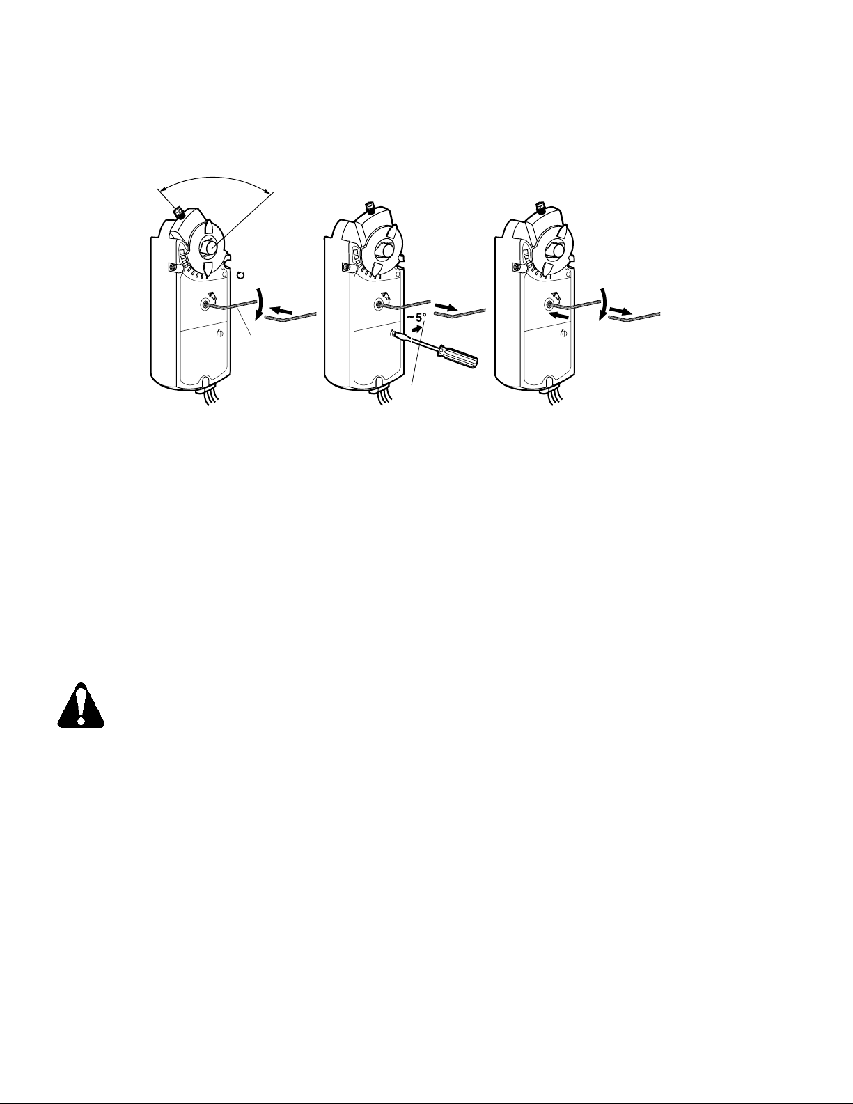
Manual Override
90˚
90˚
x 7-3/4 = 90˚
2
1
GEAR TRAIN
LOCK PIN
EA0374R2
3 mm
h
Figure 8. Manual Override.
To use manual override or set preload
(See Figure 8)
1. Insert the 3 mm hex key in the override opening.
(Step 1)
2. Turn the key in the direction of the arrow on the
hand symbol until you reach the desired degree
of opening. (Step 2)
3. Hold the key in place. (Step 3)
4. Insert a small flat-blade screwdriver into the gear
train lock pin. Turn the screwdriver in the same
direction as the arrow until you hear a click or
meet slight resistance. (Step 4)
90˚
3
GEAR TRAIN
LOCK PIN
HOLD
GEAR TRAIN
5
LOCK PIN
7
6
8
4
To release manual override or preload
(See Figure 8)
1. Insert the 3 mm hex key in the override opening.
(Step 6)
2. Turn the key in the direction of the arrow only a
short distance. (Step 7)
3. Remove the key. (Step 8)
The actuator will return to "0" position.
NOTE: Applying power and sending a control signal
will release manual override.
CAUTION:
When engaging the gear train lock pin,
be careful to turn only about 5 degrees
until you hear a click or meet slight
resistance. Turning too far will strip the
lock pin.
5. Remove the key or keep it in place.
(Step 5)
Page 4 of 7
Page 5

Document No. 129-361
Installation Instructions
August 3, 2004
Mechanical Range Adjustment
1
2
3
EA0278R1
5
4
EA0279R1
Figure 9. The Angular rotation is adjustable between
0° and 90° at 5 Degree Intervals.
Make sure the actuator is in the zero position when
making this adjustment. If making the adjustment
before the actuator is in service, take into account
the 5° preload. To release the preload, see Manual
Override section.
Other settings
For adjustment of auxiliary switches and span/offset
options, see the individual Technical Instructions.
See References.
Wiring
All wiring must conform to NEC and local codes and
regulations.
Use earth ground isolating step-down Class 2
transformers. Do not use autotransformers.
Determine the supply transformer rating by summing the
total VA of all actuators used. The maximum rating for a
Class 2 step-down transformer is 100 VA. The
recommended maximum actuators shown in Table 1
include a safety factor of 80% of the transformer VA.
Operating more actuators requires additional
transformers or separate 100 VA power trunks.
Table 1.
Actuator
MEP-4556xx
Two- and Three-position Control
MEP-4551xx
MEP-455500
Power
Consumption
Modulating Control
9 VA 9
8 VA 10
WARNING:
Mixed switch operation is not
permitted. To the switching outputs of
both auxiliary switches (A and B), only
apply:
• Standard cable (250 Vac/24 Vdc)
− UL/cUL: line voltage, or
− UL/cUL: Class 2 voltage.
NOTE: Either all six outputs of the
dual auxiliary switches must
be connected to line voltage or
all six outputs must be
connected to Class 2 voltage.
Actuators per
Class 2
Supply Circuit
Page 5 of 7
.
Page 6

Document No. 129-361
NOTE: These wiring diagrams show options that are no
longer available for certain models. To order models with the
appropriate options, see the MEP-455 series data sheet!
NOTE: Do not order actuator models
based on these diagrams! To order
models with the appropriate options,
see the MEP-455 series data sheet.
Installation Instructions
August 3, 2004
Wiring Diagrams
Modulating Control 24 Vac
MEP-4556xx
8
EA0284R1
Two-position Control 24 Vac
MEP-455100
1
M
EA0281R1
2
Three-position Control 24 Vac
MEP-455500
6
9
M
1
2
7
S1
A
S2 S3 S5 S6
S1
A
S2 S3 S5 S6
S4
B
S1
B
S4
S4
Table 2. 24 Vac Wiring.
Standard
Symbol
Function
Terminal
Connection
Color
1 Supply (SP) G Red
2 Neutral (SN) G0 Black
6
Control signal
Y1 Violet
clockwise
7
Control signal
Y2 Orange
counterclockwise
0 to 10 Vdc/4 to 20 mA
8
Y Gray
input signal
Output for 0 to 10 Vdc
9
U Pink
position indication
S1 Switch A Common Q11 Gray/red
S2 Switch A NC Q12 Gray/blue
S3 Switch A NO Q14 Gray/pink
S4 Switch B Common Q21 Black/red
S5 Switch B NC Q22 Black/blue
S6 Switch B NO Q24 Black/pink
Table 3. 120 Vac Two-Position Control.
Standard
A
M
B
Symbol
3 Line L Black
4 Neutral N White
S2 S3 S5 S6
PL0004R1
GND
1
120 Vac Two-position Control
MEP-455300
LINE
3
M
4
NEUTRAL
EA0926R1
Page 6 of 7
Function
Terminal
Connection
Color
Page 7

Note to page 6 added on 01/11
Dimensions
min. 4 in.
100 mm
3-1/16 in.
78 mm
Document No. 129-361
Installation Instructions
August 3, 2004
min. 1/4 in.
7 mm
EA1087R1
5/32 in.
4 mm
1-11/32
34 mm
1-11/32
34 mm
min. 8 in.
200 mm
min. 2-1/2 in.
60 mm
11-13/16 in.
300 mm
7-3/4 in.
197 mm
1 in.
25 mm
1-1/8 in.
28 mm
3-3/8 in.
86 mm
3-15/16 in.
100 mm
1.1 in.
28.5 mm
MAX
3/4 in.
20 mm
OPENING
FOR 3/8"
FLEX CONDUIT
(3 PLS)
11/32 in.
10 mm
1-23/32 in.
30 mm
9 in
230 mm
EA0249R2
25/32 in
20 mm
Figure 10. Dimensions of the MEP-455 ControlSet Actuator and Mounting Bracket in Inches (Millimeters).
Information in this publication is based on current specifications. The company reserves the right to make changes in specifications and models as design
improvements are introduced. ControlSet is a registered trademark of KMC Controls. Other product or company names mentioned herein may be the trademarks
of their respective owners. © 2004 Siemens Building Technologies, Inc.
KMC Controls
19476 Industrial Drive
New Paris, IN 46553
.
Document No. 129-361
Country of Origin: US
Page 7 of 7
 Loading...