

Page 1
Mounting
2.812
(71.4)
1.563
(39.7)
Tri-State/Two-Position Actuators (25/45/90 in-lb.)
MEP-4201/4501/4901
Installation Guide
Adjustable
Stop
° Rotation
Indicators
1.625
(41.3)
6.000
(152.4)
HMO-4001 Non-Rotation “T”
Bracket included with MEP-4901
HMO-4002 Non-Rotation
Bracket included with
MEP-4201& MEP-4501
Gear
Disengagement
Lever
Removeable Conduit Fitting with
(2)1/2" NPS Threaded Holes (for
use with flexible conduit only)
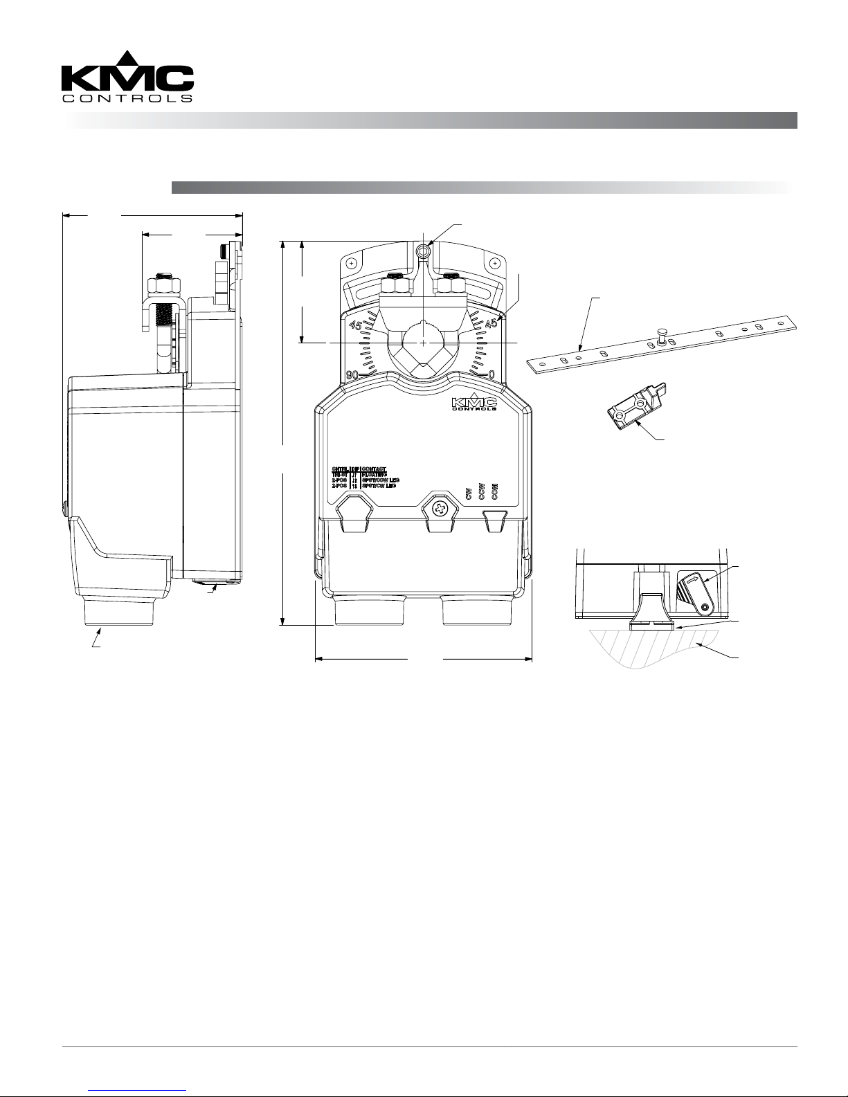
Illustration 1—Overview (Direct-Coupled Mounting)
1. Ensure the damper can move freely through its
entire range of motion, and x any binding before
installing the actuator. Turn the damper blade to
its fully closed position.
2. Press (to the right) and hold the gear disengagement lever (see Illustration 1), rotate the actuator
to the fully closed position, and release the lever.
NOTE: Depending on the damper-seal design,
backing the actuator o its stop
approximately 5° may provide tight
damper shut-o.
3. Align the actuator and slide it onto the shaft.
4. Leaving a gap between the actuator and
mounting surface to prevent any binding, ngertighten the nuts on the V-bolt.
3.406
(86.5)
5. Insert the provided (HMO-4001/4002, dependent
on model) non-rotation bracket into the slot at the
base of the actuator and secure the non-rotation
bracket with two #8 or #10 self-tapping screws.
6. Evenly tighten the V-bolt nuts (30–35 in-lbs.
on MEP-4201 model or 60–70 in-lbs. on MEP4501/4901).
7. If desired, use a 7/64-inch hex key wrench to
loosen and position the end-stop screw.
NOTE: The two holes at the top of the actuator
are NOT for use in direct-coupled
applications. (They are for remote
mounting, such as with the optional
HLO-4001 Crank Arm Kit.) For mounting
to valves, see the appropriate valve
installation guide.
Gear
Disengagement
Lever
HMO-4002
Non-Rotation
Bracket
Mounting
Surface
MEP-4201/4501/4901 1 Installation Guide
Page 2
Wiring
Switch Position
Selector
Switches
(Under Conduit Fitting)
Power/Signal
Terminal Block
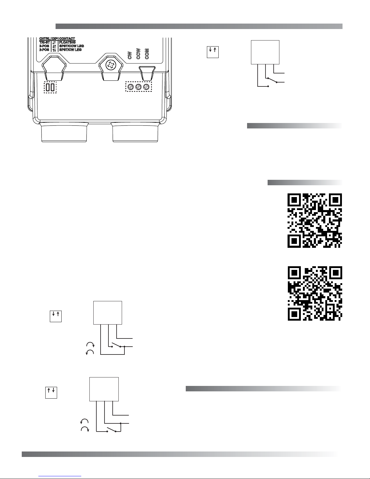
Illustration 2—Wiring Compartment
To wire the actuator:
1. Loosen the screw on the conduit ing and lift up
to remove the ing.
2. Using a utility knife or drill, cut the red plug
to accept wiring or replace the plug with an
application-specic ing.
NOTE: The red plug (or similar ing) protects
internal components from debris, helping
to ensure long actuator life.
1 2
CW
CCW
–
T
COM
–
Power Supply
24 V AC/VDC
~/+
Illustration 5—Tri-State Floating Point Control
Maintenance
No routine maintenance is required. Careful
installation will ensure long term reliability and
performance.
More Information
For models, specications,
and additional information,
see the MEP-4201/4501/4901
Data Sheet on the KMC
web site.
3. Thread wires through the plugged opening and
connect to the terminal block according to the
relevant application. Adjust the selector switch.
See Illustrations 3 through 5.
4. Reinstall the conduit ing and tighten the screw.
Switch Position
COM
T
CW
CW
CCW
T
CCW
COM
–
Power Supply
24 V AC/VDC
~/+
–
Power Supply
24 V AC/VDC
~/+
1 2
Contact Position:
Open = CW Rotation
Closed = CCW Rotation
Illustration 3—Two-Position Control, CCW Leg
Switch Position
1 2
Contact Position:
Open = CCW Rotation
Closed = CW Rotation
Illustration 4—Two-Position Control, CW Leg
For accessories, troubleshooting, torque selection,
links to sample applications, and other information, see the MEP-4xxx
Applications Guide on the
KMC web site.
KMC Controls, Inc.
19476 Industrial Drive
New Paris, IN 46553
574.831.5250
www.kmccontrols.com
info@kmccontrols.com
MEP-4201/4501/4901 2 Installation Guide
© 2013 KMC Controls, Inc. 039-019-02B
 Loading...