

Page 1
Thermic 2-Position or Time-Proportional Actuators
1
MEP-3001 (for VEP-12/22/34) and MEP-3006 (for VEP-11/21/37)
Installation and Operation Guide
Mounting
CAUTION
If mounting the actuator to a valve already in-line,
close the shut-off valves in the piping (upstream
first, then downstream) or switch off the pump to
allow the differential pressure in the valve to drop.
CAUTION
To prevent condensation from dripping onto the
actuator housing, mount the valve with the actuator
in the upright position or, at most, at a 45° angle.
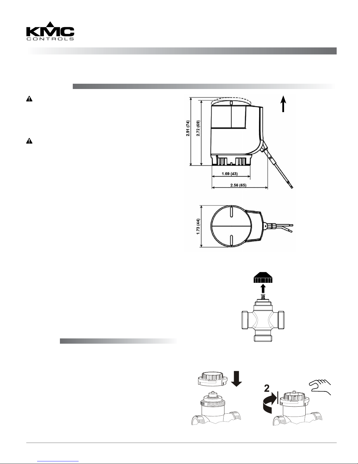
1a. On a new valve body, remove the protective cap
covering the bonnet. (See Illustration 2.)
1b. To remove an existing (same model) actuator,
disconnect the wiring, wait at least six minutes
until the actuator has completely cooled, turn
the actuator bayonet ring (coupling piece)
counterclockwise until it is loose, and pull o the
actuator. Also unscrew the old black bayonet nut
if it stays on.
UP
Brown to 24 VAC Phase
Blue to 24 VAC Neutral
2a. If the new black bayonet nut is loose from the
new actuator, screw it on top of the valve body
and rmly hand-tighten (only). (See Illustration
3.) Then place the actuator over it and turn the
actuator bayonet ring clockwise until it is hand-
tight and locks into place.
2b. If the new black bayonet nut is rmly aached
inside the actuator, screw the entire actuator on
top of the valve body until it is hand-tight and
locks into place.
Wiring
Connect the brown wire to the phase side of 24 VAC
and the blue wire to neutral. (See Illustration 1.)
For two-position control, a simple switch or relay
can be used. For time-proportional (pulse-width
modulation) control, use a KMC REE-5017 or
REE-4106/5106 relay module. (See the relevant relay
module documentation for more information.)
NOTE: All wiring must conform to NEC and
local codes and regulations. Use a Class 2
transformer.
Illustration 1—Dimensions and Wiring
Illustration 2—Removing a Protective Cap
Illustration 3—Installing the Black Bayonet Nut
MEP-3001/3006 1 Installation and Operation Guide
Page 2
Operation
Select Specifications
After the mechanical and electrical installations have
been completed, cycle the actuator to verify opera-
tion. (See Illustrations 4 and 5.)
When power is applied to the actuator, the temperature of the heating element rises, causing the
solid expansion medium to expand and stroke the
aached valve body. The valve starts to open after
preheating for approximately 1 minute if the heating
element is switched on in a cold (room temperature)
state, and achieves the maximum stroke after (ap-
proximately) another 3-1/2 minutes. At power-o,
the expansion element cools down, and the spring
closes the valve.
De-energized position (gap closed):
• For MEP-3001s, the actuator shaft
is extended and the valve is closed.
• For MEP-3006s, the actuator shaft
is retracted and the valve is open.
(Fully) energized position (gap open):
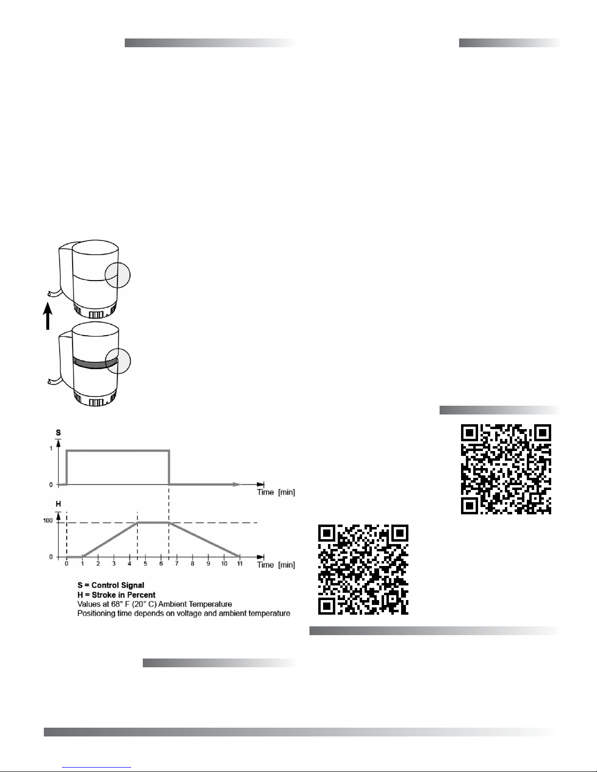
UP
Illustration 4—Position Indication
• The MEP-3001 has been connected
to the power supply for at least
4-1/2 minutes. The actuator shaft is
retracted and the valve is open.
• The MEP-3006 has been connected
to the power supply for at least
4-1/2 minutes. The actuator shaft is
extended and the valve is closed.
Power 24 VAC (± 20%), 50/60 Hz,
Class 2 only, 6 VA max.
Control Two-position or time-propor-
tional
Primary Fuse Must supply externally
Nominal Force 22.5 in-lb. (100 N•m)
Stroke Maximum 0.18 inches (4.5 mm)
Positioning Time 270 sec. @ 68° F (20° C)
Weight 0.4 lb. (0.18 kg)
Mounting Location NEMA 3 (IP54), interior only
Approvals Conforms to CE requirements
De-energized Position
MEP-3001 (NC) Actuator shaft extended, valve
closed (for VEP-12/22/34 se-
ries)
MEP-3006 (NO) Actuator shaft retracted, valve
open (for VEP-11/21/37 series)
Temperature Limits
Medium 34 to 230° F (1 to 110° C)
Ambient 41 to 122° F (5 to 50° C) @ 0 to
85% RH (non-condensing)
Shipping –4 to 140° F (–20 to 60° C) @ 0
to 95% RH (non-condensing)
More Information
For more information
on applications, see the
REE-5017 on the KMC
web site.
Illustration 5—Opening and Closing Times
Maintenance
These actuators are noise-free and maintenance-free.
Careful installation will help ensure long-term reli-
ability and performance.
MEP-3001/3006 2 Installation and Operation Guide
© 2014 KMC Controls, Inc. 006-019-01A
See also, the REE-5106.
KMC Controls, Inc.
19476 Industrial Drive
New Paris, IN 46553
574.831.5250
www.kmccontrols.com; info@kmccontrols.com
 Loading...