

Page 1
Installation Guide
Mounting
The MCP-1160 MUST be mounted on a rigid
surface due to the force generated at, or near,
maximum air pressure.
1. Align the actuator with the controlled device.
The mounting joint allows the actuator to be
located in a different plane from the controlled
device.
2. Attach the actuator to the rigid surface through
the four 3/8" (4 mm) holes in the mounting
bracket.
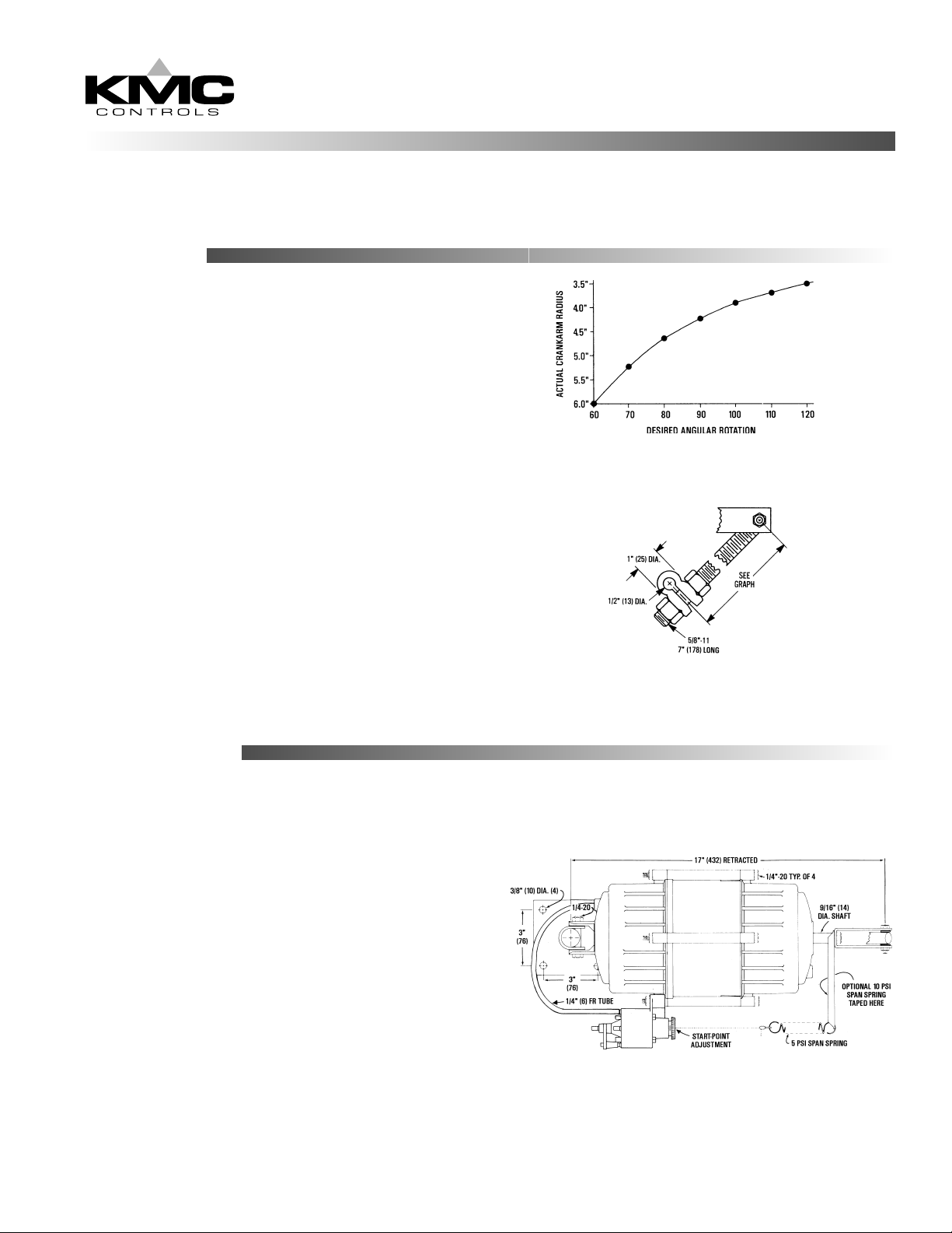
3. Adjust the crankarm assembly from 60° to 120°
rotation as required.
6” Pneumatic Damper Actuator
MCP-1160 Series
4. DO NOT tighten the universal joint. The
actuator must be free to swivel as it operates.
Connections
MCP-1160 models ordered with positioners are
factory piped.
♦ Use 1/4" (6 mm) O.D. FR polyethlyene tubing.
♦ Use only clean, dry control air. No attempt
should be made to use any other medium.
1 Connect the actuator input to the positioner
output, Port “1”.
2. Connect the input signal to the positioner to Port
“2”.
3. Connect the main air (20 psi) to the center port.
NOTE: If the application requires operation near
the maximum temperature and maximum
pressure, add a tubing restraint to the actuator
connection.
Page 2
Adjustments and Calibration
DANGER
The MCP-1160 contains a large powerful spring.
Exercise extreme caution if disassembly is required.
The actuator shaft MUST be restrained to prevent
the spring from expanding.
The MCP-1160 contains an 8-13 psi spring. A
positioner allows the unit to operate over any 5 psi
span with the start-point adjustable from 3-10 psi.
Replace the 5 psi spring with a 10 psi spring to widen
the span.
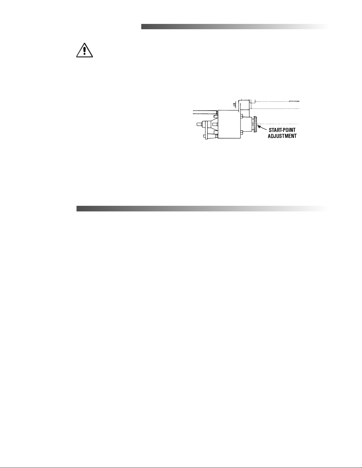
To change the positioner start-point:
1. Apply the desired signal pressure
2. Rotate the start-point adjuster until the actuator
starts to stroke.
Maintenance
The MCP-1160 actuator is designed for long term
reliability. No routine maintenance is required,
however care should be taken during any installation
or maintenance due to the power of the actuator.
KMC Controls
19476 Industrial Drive
New Paris, IN 46553
574.831.5250
www. kmccontrols.com
016-019-01
 Loading...